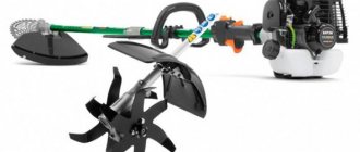
Scraper buckets
A scraper ladle is a device designed for loading, transporting and unloading ash and slag in coal boiler houses.
Removal of ash and slag into the ash bin is carried out by a ladle moving along guides in the slag collection channel. The slag collection channel is constantly filled with water, which eliminates air leaks into the boiler furnace and sintering of the slag and eliminates smoke in the ash rooms.
PSKM scraper lifts are produced in the following models:
PSKM-0.35-75 ° - 900; PSKM-0.35-65 ° - 900; PSKM-0.5-75 ° - 900; PSKM-0.5-65 ° - 900;
PSKM-0.35-75 ° - 700; PSKM-0.35-65 ° - 700; PSKM-0.5-75 ° - 700; PSKM-0.5-65 ° - 700.
Technical Specifications of Scraper Lift
- productivity from 5 to 7 m3/h;
- bucket capacity from 0.35 to 0.5 m3;
- elevation angle up to 75 °C;
- winch pulling force 24 N;
- weight, no more than 5550 kg;
- operating mode - automatic, semi-automatic.
Design of scraper bucket-shovel. The bucket can rotate freely about an axis that is attached to the traction frame. When the ladle moves in the horizontal direction, when capturing slag, its rear end rises upward, however, approaching the inclined plane, the thrust frame, rigidly connected to the ladle, rests against the guides, thus bringing the ladle into a horizontal position and thereby facilitating its movement along the inclined parts of the channel.
The bucket consists of two parts of the frame box. The axle assembly, front and rear, is secured to the bucket frame with bolts. Both axles are equipped with flanged rollers. Wedge couplings are attached to the rear axle, which are designed to attach the bucket with a rope. The entire box does not include the front panel.
The back wall of the bucket tilts inward using hinges. Folding in the opposite, outer direction is impossible due to the emphasis on the bottom of the box.
The bottom of the box is equipped with teeth for loosening slag and ash residues at the bottom of the channel.
The front part of the box, when in a vertical position, is movable relative to the frame, which in turn significantly reduces the coefficient of resistance exerted on the passage of the bucket in the channel when using idle speed.
In order to improve the performance of the bucket and facilitate the flow of water during its movement along the inclined part, the side walls, as well as the bottom wall of the bucket, are perforated.
The tension device of the tail section of the PSKM lift consists of a frame with a block with a diameter of 50 cm and a frame. The tensioner box slides freely and unhindered along the frame guides. Material poured into the box with a mass of up to 800 kg creates the necessary force for proper tension of the ropes, which in turn contributes to the most stable position of the rope in the streams of the supporting and guide blocks.
Shut-off devices are designed for emergency stop of the winch in the event of a break or significant traction of the rope, as well as in the event of a jammed bucket in the channel.
Scraper method of stripping operations using the bulldozer-scraper method of development
The technology of the scraper method of stripping work is in many ways identical to bulldozer work.
Rock excavation.
When the scraper moves at first speed, a bucket with a raised flap is lowered onto the face and the chips that enter the bucket are trimmed (Fig. 29, a). First, the chips move along the bottom of the bucket 1 to the rear wall, then are squeezed into the upper part of the bucket 2. The resistance to the movement of the chips increases, they begin to collapse, which leads to the formation of the front shaft 3, which increases the resistance of the chips to compression and continues to flow into the bucket. In loose rocks, the possibility of rock entering the bucket is reduced, making it difficult to fill the back of the bucket. The closing valve cuts off part of the rock of shaft 3, which is formed in front of the bucket. This increases the fill factor of the bucket, so before raising the bucket, you must first lower the damper. The length of the loading path of the bucket varies from 10 to 50 m. When the bucket is not filled enough, side flaps 4 are sometimes strengthened to increase rock capture when closing the damper. The bucket is best filled in rocks of medium strength, when no great effort is required for cutting, and the separated chips have sufficient resistance to compression, which makes it easier to push it into the bucket.
Excavation of rocks with wheeled scrapers is carried out in the following main ways: adjacent horizontal chips, comb chips, with loosening, with a pusher, and inclined chips.
When excavating with adjacent horizontal chips, the rock is cut in layers 10-20 cm thick in the order 1, a, 1, b, and then stripes 2, 3, 4 (Fig. 30, a). After this, they move on to excavating the underlying layers. To better fill the bucket, it is advisable to trim thicker chips, but you should not allow the tracks to slip. With this method, rock excavation can be carried out separately according to the layers of occurrence. It is difficult to completely fill a large bucket this way and takes a long time to fill. The method of excavation with adjacent horizontal chips is used for excavation of category II rocks, non-friable rocks of category I, occurring in thin layers or layers up to 1-1.5 m thick, or when separate (layer-by-layer) rock excavation is necessary. This method is common on frozen placers for excavating rocks in the summer as they thaw. Productive work is possible with a thawed layer of at least 5-7 cm. Data for filling a bucket with a capacity of 6-10 m3 for the method under consideration are given in table. 12.
During excavation with comb chips (Fig. 30, b), pillars 1-1.5 m wide are left between the separately trimmed chips. As a result, the trimmed chips acquire a comb shape and are twice as thick in the middle part. The flow of such chips into the bucket is facilitated. Thanks to this, the fill factor of the bucket increases by 10-15%, and loading time is reduced by 10-20% compared to the previous method. For ease of movement of the tractor, the width of the ridge should be less than the width of the clearance between the tractor tracks. This method is used for excavating rocks of categories II and III.
When excavating with loosening (Fig. 30, c), the rocks are first loosened with a tractor ripper or uprooter. The loosening methods are the same as for bulldozer excavation. The depth of loosening is 15-40 cm, while they strive not to over-grind the rock, but to limit themselves to the passage of furrows that facilitate cutting of chips. Excavation with loosening is usually used for rocks of categories IV-V, sometimes III. Loading the bucket is then easier and the fill factor increases.
Rock excavation with a pusher (Fig. 30, d) is based on the fact that an additional tractor pushes the scraper while filling the bucket. A ram is installed in front of the pusher tractor, with which it rests against a buffer mounted on the rear frame of the scraper. Often a bulldozer with a raised knife is used for these purposes. At the same time, in order to avoid damage to the scraper cylinders, the buffer is extended or the old cylinder is strengthened on it. A excavation with a pusher is used in rocks of III-IV categories. Using a pusher allows you to cut thicker chips and thereby increase the fill factor by 15-20% and reduce loading time, reaching the loading of the bucket with a cap. One pusher can serve from three to five scrapers. With this method, scraper downtime increases by 1-5%, since time is inevitably lost waiting for the pusher, so organizing the excavation process becomes somewhat more complicated. This method is widely used when operating self-propelled scrapers.
When excavating with inclined chips, the bucket is filled at the face with a slope of 0.08-0.15 while the scraper is lowered into the cut (Fig. 30, e). This allows you to cut thicker chips and fill the bucket more fully. In addition, the rock shaft formed in front of the bucket increases, and consequently the volume of rock captured by the damper also increases.
The face slope is selected based on observations. Excavation of rocks can be carried out in adjacent or combed shavings, while rocks from individual layers are mixed. The time and distance for loading with this method are reduced, and the filling of the bucket increases in non-friable rocks by 10-15% compared to excavation with horizontal chips. Excavation with inclined chips is used on thawed placers composed of rocks of categories II and III with a thickness of the mined bench of more than 1.5 m.
In spring, rock excavation with scrapers begins after the permafrost has thawed to a depth of at least 5 cm; To speed up thawing, the rocks are loosened. In autumn, during frosts, the frozen crust should be loosened. On blasted frozen lumpy or boulder rocks, scrapers with a bucket with a capacity of up to 15 m3 do not work well; for these conditions, scrapers with a bucket with a capacity of 35 m3 are required.
Formation of dumps.
Peat delivered to the dumps is poured out in a layer of 10-30 cm, depending on the height of the bucket while the scraper is moving. The dumping of rocks during unloading can be done on the upper surface of the dump or on its slope.
On the surface of the dump (see Fig. 29, b), the rock is usually laid in horizontal layers. The tilt of the bottom in this case does not exceed 65°, which slows down the emptying of the bucket and requires increased power consumption for tipping the bottom. To unload a bucket with viscous rocks, this tilt is not enough, and you have to shake the bottom. For these reasons, when moving on loose surfaces, you need to shift the speed to second, and sometimes to first gear. The length of the unloading path is 5–25 m, and its duration, depending on the viscosity of the rocks, is 0.3–0.6 minutes. This laying method is advisable to use during the initial formation of a dump, when you need to quickly increase its height or when layer-by-layer laying of rock with simultaneous compaction is necessary, for example, when constructing dams.
When unloading rock on a slope (see Fig. 29, c), the scraper moves down a slope of 14-25°. This allows the bucket to be unloaded without reducing the speed of the scraper. In addition, the bucket angle increases to almost 90°. Thanks to this, unloading is accelerated and takes 0.15-0.3 minutes. This installation method is the most common.
Unloading viscous clay rocks is difficult because during filling in the rear part of the bucket the rocks are pressed so tightly against the walls that they do not fall out of the bucket when the bottom is lifted. As a result, the use of the bucket capacity is reduced and the downtime of the machine for cleaning it increases, and the work of the scraper becomes ineffective.
The external contours of the dump depend on the opening method, which determines where the scraper will reach the surface. When opening with continuous exits, the dump in the cross-section is represented by a triangle (see Fig. 26, a and b), in which the slope towards the cut has the greatest calculated rise i, and in the rear slope an angle b is maintained, allowing the possibility of lowering the scraper, i.e. no more than 25°. The dimensions of these dumps are calculated in the same way as bulldozer blades. If the opening is carried out in separate trips, the trip continues on the dump until the required height is reached, and then the dump is increased both along and towards the cut (Fig. 31), as a result of which in cross-section the dump takes on the shape of a trapezoid. The blade height h is determined by the equations (see problem book):
where A, e e, m are the angular coefficients;
D is the length of the scraper with tractor, m.
The upper signs should be used when the blade is located on a slope, the lower ones - on a slope. For a horizontal surface, I2 = 0 and e = 0.
The width of the blade base in this case is determined by the
Stripping System equation.
The procedure for conducting overburden workings is interconnected with the location of the face and dump of peat and the direction of their movement. All this predetermines the location of the scraper drive and the direction of the working path of vehicles in the drive. Based on the direction of the working path in the drive, the systems are divided into single (one-sided) and double (shuttle, double-sided). The location of the race affects its outline (shape) and on this basis systems with a ring, loop and figure eight race are distinguished.
With single systems (Fig. 32, a, b, c), one bucket is delivered from the face to the unloading site for a full run (revolution, cycle). In this case, the relative mileage of the scraper within the section on wide placers will be the smallest with a relatively constant length of the mileage on the surface. However, for one delivered bucket it is necessary to make the greatest number of turns of the scraper (at least four). Therefore, it is more advantageous to use a single system on placers of medium and large width, i.e., more than 60 m. The length of the drive during mining of the area varies from the smallest during excavation along the side at the exit to the greatest when excavating in the middle part or at the opposite side of the cut. Single systems are characterized by ease of operation with significant unevenness in machine performance. These systems are used for both unilateral and double-sided opening.
With dual systems (Fig. 32, d, e, f), two buckets are delivered with a scraper per closed run. To use it, it is necessary to go through opening mines and place dumps on both sides of the mine. The scraper is lowered into the cut along one side, while moving across the placer the bucket is filled, and it is driven to the surface along the opposite side, on which the bucket is unloaded. After unloading, the scraper is lowered into the cut again, the bucket is filled a second time, and unloaded into a dump on the surface near the side along which it was first lowered into the cut. With this procedure, the number of scraper turns per one delivered bucket is halved. The length of the runs is quite constant and varies within small limits, but the mileage of the scraper directly in the section increases significantly. For these reasons, dual systems are more profitable to use on narrower placers less than 60-100 m wide, especially when opening in continuous exits.
During the race, cars move clockwise or counterclockwise; To ensure uniform wear of ropes, blocks and chassis, it is necessary to change the direction of turns of the cars during the race. During roundabouts, their outlines approach the irregular ring (see Fig. 32, a, d). The ease of performing races increases the rhythm of the machines, and on wider fields the relative length of the race is also reduced, thereby increasing the productivity of the machines. Races with the outline of a figure eight (see Fig. 32, b, d) are used to change the direction of turns of the scraper in the section and on the dump, this ensures uniform wear of the running parts. Systems with figure-eight races have a slightly longer race length. Systems with loop drives (Fig. 32, c, e) are used when opening separate exits, when the location of the dumps and exits does not allow simplifying the movement of vehicles.
When choosing a system, it is necessary to maintain such an order for conducting overburden workings in which the least amount of time would be spent on delivering one bucket. It is also necessary that the vehicles have to turn less during the cargo run. The length of the drive depends on the opening method, the stripping system, the excavation method, the width of the blade and the width of the placer. The shortest drive for a one-way ring system when opened with separate exits (Fig. 33, a and b) corresponds to the length of curve 1, 2, 3, 4, and the longest - curve 1, 5, 6, 7, 8. The theoretical length of the average drive in general form it is determined by the equation where Lв = 0.5 (lм + lб) is the average length of the path of movement of the scraper within the section along the fall of the placer, m;
lm, lb - respectively, the path of the scraper along the fall of the placer during the shortest drive and during the longest drive, m;
p—distance of movement from the base of the cut to the base of the dump, m;
Bс is the average length of the path across the placer, m;
dc — average distance of movement across the dump, m;
n—arrival coefficient; for a single-ring system n = 1, for a double-ring system n = 2.
The average length of the path of movement of the scraper within the section along the fall of the placer Lв (see Fig. 33, a) depends on the method of opening and excavating rocks. The equations for determining this distance are given in table. 13.
The average length of the path across the placer with single systems is determined in the same way as with bulldozer runs. For dual systems, Bc = B + 2e.
The performance of the scraper depends on the condition of the track, so it is necessary to level its surface and drain rain and groundwater. The path is leveled with a bulldozer or scraper.
For 6-7 working scrapers to perform these auxiliary works, one bulldozer is attached, which is used to level exits and ramps into the cut, make cutting and drainage ditches, pour crossings through the ditches, having previously laid pipes with a diameter of 400-500 mm in them to pass water, remove the upper vegetation layer and dumps are dumped. The volume of all this work is usually 3-4% of the volume of all stripping work.