Description of the circuit operation.
The electrical circuit diagram of all such cars is identical and differs only in design. The KamAZ brake light circuit includes sensors, an intermediate relay, a buzzer and a parking brake warning lamp, and of course warning lamps in the rear lights of the tractor and trailer.
The sensors are installed on the brake system circuits in the area of the brake valve and are triggered when the pressure in the circuit changes. On the latest models, a push-button switch installed under the pedal is used as a brake light sensor, as on most cars. When you press the pedal, the pressure in any of the circuits changes, which leads to the closure of the sensor contacts. If there is a push-button switch, the contacts close mechanically due to the action on the button. In this case, the intermediate relay winding is connected to the vehicle ground. In this case, the current from the fuse passes through the relay winding, the contacts of one of the sensors or the switch under the pedal. The relay contacts close and supply power to the warning lamps in the rear lights.
When the parking brake is applied, in addition to the warning lights, the parking brake warning light begins to flash. This occurs due to the fact that the parking brake switch and control lamp receive a minus signal through the parking brake sensor.
Since all sensors are connected to the intermediate relay coil, when any sensor is shorted, a minus appears on all sensors. In order to prevent the warning lamp from turning on when other sensors are triggered, a diode is included in the circuit, which prevents the minus from reaching the parking brake sensor wire.
Brake systems
BRAKE SYSTEMS
Braking mechanisms are drum type with two internal pads. The front brake chambers are diaphragm, the rear ones are with spring energy accumulators.
The drive of the service brake systems is pneumatic, separate. The number of receivers is 5, with a total volume of 100 liters, for the KAMAZ-6540 vehicle - 6 receivers, with a total volume of 120 liters. Nominal pressure in the pneumatic drive (6.5-8.0 kgf/cm2).
Adjust the strokes of the brake chamber rods if the value exceeds 45 mm. Depending on the stroke of the rod, the gap in the brake mechanisms between the brake lining and the drum changes. Before adjusting the strokes of the rods, bring the pressure in the pneumatic drive to the maximum value (the pressure regulator should operate). To achieve maximum pressure in the rear brake circuit, move the brake force regulator lever to the upper position and fix it while making the adjustment. The brake drums should be cold and the parking brake should be off. Adjust the gap by turning the worm axis of the adjusting lever, having previously loosened the locking plug one or two turns (see Fig. Adjusting the gap in brake mechanisms). By turning the worm axis, set the stroke value of the brake chamber rod according to the Table Limits of adjustment of the brake chamber rod stroke depending on the length of the adjusting lever arm. It is necessary that the rods of the right and left chambers on each axle have, if possible, the same stroke (the difference is no more than 5 mm) to obtain the same braking efficiency for the right and left wheels. For more efficient brake operation, it is recommended to set the rod stroke to the lower limit of the values indicated in the table.
Adjusting the gap in brake mechanisms
Automatic adjustment lever
After adjustment, after 2...5 km, check the heating of the brake drums; if the drum temperature is more than 60-80°C, release the adjustment lever one click to increase the stroke of the chamber rod.
Vehicles are also equipped with the installation of adjustment levers with automatic adjustment of the gap in the brake mechanisms between the brake lining and the drum (see Fig. Automatic adjustment lever).
Adjustment of the strokes of the brake chamber rods with an automatic lever should be done when overhauling the brake mechanisms (replacing pads, etc.), when the brake chamber rod is in a completely released state (release the energy accumulator using the parking brake control valve). Carry out the adjustment, having previously fulfilled all the conditions, regarding the pressure in the pneumatic drive and the position of the brake force regulator lever (p. 21-1) according to the diagram (see Fig. Adjusting brakes with automatic levers) in the following order:
- make sure that the lever is moved by hand in the direction of braking and completely returns to its original position;
— by rotating the worm of the adjusting lever, align the holes in the lever body and the brake chamber rod fork. Attach the brake chamber rod using a pin, washer and cotter pin (see Fig. Adjusting brakes with automatic levers, 1);
— press the control block of the adjusting lever all the way in the direction of its rotation in the direction of the arrow indicated on the body (see Fig. Adjusting brakes with automatic levers, 2):
— connect the fixing bracket and the control block of the lever with a bolt and nut, without disturbing the position of the control block;
— by rotating the worm of the adjusting lever, release the pads until they come into contact with the brake drum (see Fig. Adjusting brakes with automatic levers, 3):
— turn the worm in the opposite direction approximately 3/4 of a turn (see Fig. Adjusting brakes with automatic levers. 4). In this case, the characteristic operation of the gear coupling of the adjusting lever should be felt and the turning moment of the worm should be at least 42 N.m;
— make sure the lever is working. To do this, make 5 braking stops, pressing the brake pedal all the way. In this case, the lever worm should turn clockwise at a certain angle (see Fig. Adjusting brakes with automatic levers. 5);
— check that when compressed air is supplied and released, the brake chamber rod moves without jamming. The stroke of the chamber rod must be within the limits specified in the table Limits for adjusting the stroke of the brake chamber rod depending on the length of the adjusting lever arm for the front and rear brake mechanisms. For a larger stroke, adjust it by rotating the worm;
— make sure that when the drum is braked, it rotates evenly and freely, without touching the pads.
| Brake chamber rod stroke, mm | |
| 125 | 30…40 |
| 150 | 35…45 |
| 165 | 40…50 |
Adjustable brakes with automatic levers
To maintain the required pressure of compressed air supplied from the compressor, as well as cooling and releasing condensate, in the brake system of the car, depending on the models and trim levels, the following are used:
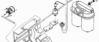
— moisture-oil separator, made in conjunction with a pressure regulator;
— adsorbent air dryer 3 (see Fig. Air dryer with pressure regulator) or “KNORR BREMZE” (Germany), made together with a pressure regulator.
Air dryer with pressure regulator 1 - cap; 2 - pressure regulator; 3 - air dryer
The compressed air supplied from the compressor to the dryer passes through the felt disc and granulate, is cleaned and goes further into the brake system. After the brake system is filled and the pressure regulator is activated, the granulate is cleaned of moisture by air escaping into the atmosphere through the atmospheric outlet of the desiccant from the regeneration receiver, intended for purging the desiccant.
Maintenance of a desiccant dryer involves periodically replacing the filter element as it becomes dirty (about once a year).
Adjust the compressed air pressure in the pneumatic drive with screw 2 of the pressure regulator (see Fig. Moisture-oil separator with pressure regulator. Air dryer with pressure regulator). When the screw is screwed in, the amount of adjustable pressure increases, and when turned out, it decreases.
To inflate tires, the pressure regulator has an air bleed valve, closed with cap 1 (see Fig. Moisture-oil separator with pressure regulator. Air dryer with pressure regulator). When bleeding air with a tire inflation hose from the tool kit, connect it instead of the cap, screwing the wing nut all the way, and reduce the compressed air pressure in the pneumatic drive, because when the compressor is idling, there is no air bleed.
To reduce pressure, open the condensate drain valve on any receiver or operate the brake valve several times.
Monitor the presence of condensate in the receivers daily; if it appears, check the functionality of the pressure regulator or moisture-oil separator. The compressed air pressure in the pneumatic drive must be nominal.
Open the condensate drain taps by moving the pusher to the side (see Fig. Pusher). Do not pull the stem down or push it up. After draining the condensate, bring the compressed air pressure in the pneumatic drive to nominal.
Water-oil separator with pressure regulator: 1 - cap; 2 - pressure regulator screw
Pusher
The vehicle's working brake systems are controlled by a two-section valve driven by a pedal.
Adjust the position of the brake pedal relative to the cabin floor according to the diagram for installing the pedal on the brake valve. By adjusting the installation and adjusting bolts, it is necessary to ensure that the pedal platform is positioned at an angle of 35±2° and the free play of the pedal is 10-15 mm. Secure the installation bolt with a lock nut, cover the adjusting bolt with UG7 sealant before adjustment.
Scheme of installing the pedal on the brake valve: 1 - pedal; 2 — pedal platform; 3 - installation bolt; 4 - adjusting bolt; 5 - lock nut.
To prevent contamination of internal cavities, protective nets are installed in the supply lines of the brake valve, accelerator valves and trailer brake control valve.
The mesh must be cleaned of dirt at every seasonal maintenance.
To adjust the braking force of the wheels of the rear axle (rear bogie), a brake force regulator (PTC) is used. The change in the amount of braking force is carried out by the RTS, which changes the air pressure supplied to the brake chambers, depending on the weight state of the car.
When the vehicle is loaded, the PTC lever moves to the upper position, automatically increasing the pressure in the brake chambers.
It is prohibited to dismantle the RTS and tie the lever.
The pressure value and length of the RTS lever for a loaded vehicle must be set in accordance with the Table of setting parameters of the brake force regulator:
Table of setting parameters of the brake force regulator
| Brake force regulator parameters | Automobile model | |||||||
| 43253 | 43255 | 53229 | 55111 | 65115 | 65116 | 65117 | 6540 | |
| Statistical deflection of suspension, F, mm | 80 | 80 | 35 | 36 | 35 | 35 | 35 | 35 |
| Lever length, L, mm | 125 | 125 | 90 | 90 | 90 | 90 | 100 | 100 |
| Load on rear bogie (empty), kgf | 2900 | 3450 | 3530 | 5200 | 5600 | 3700 | 5450 | 5350 |
| Pressure, (kgf/cm2 ±0.2) | 2,1 | 2,1 | 2,65 | 2,4 | 2,85 | 2,4 | 2,6 | 2,6 |
| Load on rear bogie (laden), kgf | 9060 | 9100 | 19000 | 16700 | 18800 | 17450 | 18000 | 18800 |
| Pressure, (kgf/cm2+0.2) | 6,0 | 6.0 | 6,0 | 6,0 | 6,0 | 6,0 | 6,0 | 6,0 |
Electrical circuit malfunctions.
During operation, some malfunctions are possible. The most common, for all cars, is when the brake warning lights do not light up. In this case, you need to check whether the lamps are lit when the parking brake is applied or not.
If the lamps are on, then the sensor is faulty or the wire from it to the relay is broken. To check, you need to disconnect the wire from the sensor and connect it to the vehicle ground. If the warning lights come on, the sensor is faulty. Otherwise, there is a break in the wire. If the lamps do not light up when the parking brake is applied, it is necessary to check the serviceability of the fuse, warning lamps and relays. Defective elements must be replaced.
The cause of the malfunction may also be a break in the wire connecting the relay to the warning lamps. If the warning lights come on when you press the brake pedal, but do not light up when you apply the parking brake, then you need to check the serviceability of the sensor, connecting wire and diode. It’s better to start by checking the diode, which is located on the board of the instrument panel warning lights, near the parking brake control paw. If, when applying the parking brake, a minus appears on the diode, then the sensor and connecting wire are in good condition. Otherwise, you need to disconnect the wire from the sensor and connect it to the vehicle ground. If a minus sign does not appear on the diode, then it is necessary to eliminate the break in the wire; if it appears, replace the sensor.
Another malfunction is when the warning lights are constantly on. Unlike those described earlier, this is typical only for the KamAZ stop signal. There may be several reasons. The first is the shorting of the positive wire to the signal lamp wire; in practice, it occurs if the wiring was melted in the process of shorting the positive wire to the ground of the car. The second reason is sticking of the signal lamp relay contacts.
To check, just remove and put this relay back into the socket. If the relay is working properly, a characteristic click will be heard. A faulty relay must be replaced.
How to change oil
The oil change should depend on the maintenance frequency. Before you start changing the oil fluid, you need to warm up the engine for 10-15 minutes. After this, you should wait until the power unit cools down. Before the procedure, you need to prepare a container to drain the old liquid.
To drain old oil, you must:
- Unscrew the plug on the crankcase body, which is located at the bottom of the sump.
- Drain the old fluid.
- Remove worn filters and install new filter elements.
- Close the pan plug.
- Pour new oil into the engine system.
- Conduct an external inspection of the mechanism for leaks.
- Warm up the engine to operating temperature.
When draining the old working fluid, it is recommended to inspect it for the presence of various impurities. This will help determine whether the engine needs to be flushed.
Malfunctions of brake lights of Kamaz vehicles
In addition to the direction indicators, the light signaling system of KamAZ vehicles includes circuits for switching on brake lights and reverse lights. In principle, these circuits are simple, but sometimes it can be difficult for a person without experience to find a fault on their own. Therefore, I will try to help you save time and money and tell you how to solve brake light circuit problems yourself. So - the brake light circuit.. The first thing you should do is check the fuses. If you find that the fuse has blown, you should look for the short circuit. Do not under any circumstances try to install a fuse of a higher rating or a “bug”. I think there is no need to explain what this could lead to. To determine which harness has a short circuit, you must first turn off both rear lights, then disconnect the wiring harness running along the chassis frame. It is on the frame that a short circuit most often occurs, but sometimes the problem lies in the lights. And recently, due to poor quality, flashlights (even new ones) are increasingly becoming the culprits of malfunctions. It can only be found by visually inspecting the wiring and the condition of the lights.
click to enlarge
If there is no short circuit and all the fuses are intact, but the brake lights do not work, then there may be several reasons for this, but the main one is the failure of relay K5 (see diagram). It is located in the central compartment of the cockpit panel, along with the others, and it is quite easy to “calculate” it. You just need to pay attention to the colors of the wires of its connector; they should be located as shown in the diagram below. This relay is controlled using the closing switch S5 (“frog”).
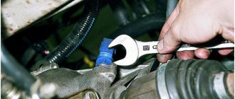
By the way, do you know where this name came from? The fact is that the brake light switches on Soviet trucks vaguely resembled this amphibian in silhouette. They were installed on a pneumatic system and quite often failed. But every driver knew where the “frog” was and often carried a spare one with him. Needless to say, the level of training of drivers in the USSR and the maintainability of Soviet cars made it possible to carry out repairs, as they say, “in the field.” The brake light switches of modern models of the KamAZ family rarely fail. I don’t remember almost a single case where this switch was to blame for the lack of brake signals. It is located under the front trim of the cabin (see photo below). If necessary, the contacts of the wires to the switch can be closed to check the serviceability of the brake signal circuit.
Summarize. As a rule, there are three problems in the brake light circuit: a faulty relay, a short circuit and... banal driver inattention. Sometimes people come to me with a complaint that “the brake lights suddenly disappeared..” In fact, it turns out, in about 5 percent of cases, that when checking the vehicle, the driver either did not turn on the ignition or did not pump up the air (in early Kamaz car models). Therefore, be careful and good luck to you!
Where is the stop signal frog on a Kamaz
Everyday life of a Kamaz driver - Making a stop signal
where is the brake light sensor located (frog)
Ural 4320 are the brake lights constantly on? Go to the frog (switch) from ZIL.
How to check the switch, "frog", reversing lights
How to improve the brakes on a Kamaz
How to remove the main brake valve on a Kamaz 5511 car
Air leak from the brake valve KAMAZ ZIL PAZ MAZ KRAZ GAZ
I stopped by for repairs. Problem. The rear brake lights are constantly on.
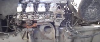
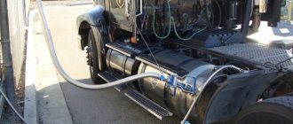
A search for brake light frogs led to their location on the frame near the middle axle.
Having unhooked them, the problem did not go away; an inspection of the wiring in the cabin revealed that the ground wire at the fuse box had warmed up. Only he fused. it goes in a braid, which is where the wires from the brake light frogs go.
Total: dismantling the braid down to the batteries and replacing the wire with a new one, with the repair of other cores stuck to it. Reason: poor standard ground from the battery to the engine. when you turn the starter for a long time while pumping fuel, then there is not enough original mass and all the mass wires that are tied to the battery begin to warm up. Recommendations: transfer additional mass from the battery to the frame and engine. With a cross section of at least 20-25 mm.
Everyday life of a Kamaz driver - Making a stop signal
The brake lights don't light up. How to find a fault.
where is the brake light sensor located (frog)
Replacing the Volvo S80 brake light relay
Wiring on KAMAZ. Part 2. In the cockpit.
KamaZ stops at night
Learning to read a car's electrical diagram. Part 1. Auto electrics.
Where is the relay located
The starter relay is located behind the switch panel.
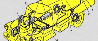
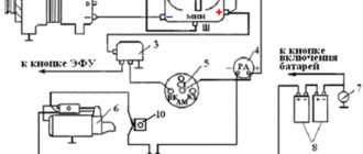
The figure shows a diagram of the location of the fuse and relay in the KamAZ device.
1 - relay, which is located on the dashboard of the car; 2 — safety system device; 3 — relay power supply; 4 - fuse in position F1; 5 — relay for pressing on the starter; 6 - relay located on the signaling device; 7 - windshield wiper for relay; 8 - turn signal relay.
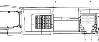
The figure shows the relay arrangement on the dashboard.
1, 2, 3, 4 - a description of the characteristics of the points is presented below; 5 - relays that provide heating of the fuel tank; 6 - relay inside the EFU device; 7 - relay that ensures the operation of the lights; 8 — relay device for the stopping system regulator; 9 — fog light relay; 10 - oil accumulator relay.
Below is a list of relays used.
Cummins Engine Installation Mechanisms:
- ABS based relay;
- a relay that provides starter blocking;
- brake system relay;
- clutch device relay.
KamAZ engine installation mechanisms:
- ABS based relay;
- relay based on the additional brake.
Before you begin disassembling the relay, you need to do a complete technical diagnosis of the truck device.
Effective “recipes” for maintenance and repair of brake lights: advice from professionals
The purpose of the brake light is to warn drivers behind you about braking. It should turn on as soon as the brake pedal is pressed. If the stop is faulty, it can cause an accident. The article discusses the brake light, the principle of operation, typical malfunctions, methods for eliminating them, and provides instructions for replacing them yourself.
Error codes KamAZ 65115 Cummins Euro 4
Many drivers are interested in the question of why the electronics release gas on KamAZ-65115. The reason for this may be an engine malfunction, dead batteries, etc. Many people decide to self-diagnosis their car; this is not recommended, since the device system is quite complex and requires the work of a specialist.
The principle of operation of the brake light
The brake lights are located at the rear of the car. Red lanterns. They light up automatically if the driver brakes. When the driver takes his foot off the brake pedal, they are also automatically turned off. The presence of stops is mandatory for vehicles.
The lights should be located symmetrically and burn brighter than the side lights. Brake lights are installed on the sides, on the rear window, in the center above the line of the side stops.
Primary and secondary brake lights can be a single bulb, a neon tube, or a set of LED bulbs. The car enthusiast is additionally equipped with a brake light repeater. The rear brake light can also serve as a fog light. You can install a formula 1 brake light (the author of the video is Mikhail Ermolaev).
The simplest brake light includes a breaker (switch) and a flashlight. The brake light switch is often called the frog switch. The plastic body of the breaker contains two terminals, a rod and a spring. This device is installed on the brake pedal.
When the driver presses the pedal, the rod enters the breaker body, the contact closes and the light comes on. As soon as the driver removes his foot from the brake pedal, the spring pushes out the rod, the contacts open and the light goes out.
LED brake lights consist of a chip and a sensor, which in this case is a frog, it sends a signal when the driver presses the brake. As with the single lamp, the frog is mounted under the brake pedal.
Foot control device diagram
Any pedal has free play. Therefore, although the driver presses the pedal, the car does not brake immediately. The brake light comes on as soon as the brake pedal is pressed. Drivers of vehicles behind will become aware of braking before the vehicle begins to brake. This way they have time to prepare for braking.
Possible malfunctions: signs and causes
If the feet do not burn, the reason may be the following:
- bad contacts;
- damage to the wiring located in the corrugation between the door and the body;
- burnt out lighting elements.
There is a situation when the brake lights are constantly on if the side lights are on. In this case, the headlights may not light up. If they are turned off, additional lighting fixtures operate normally.
- the contacts of the parking lights and stop lights have been short-circuited;
- there is no weight on the dimensions;
- the two-pin lamp is faulty;
- the circuit closed, but did not open.
If the parking lights and brake lights are on and the ignition is turned off, then you need to check whether the lampshades are shorted to the housing. The reason may be poor contact of the negative wire with ground.
Methods for troubleshooting
Troubleshooting is not a complicated process and even novice car enthusiasts can do it (the author of the video is Avtoelektika VC).
First of all, you should check the integrity and condition of the wiring.
Using a multimeter, you need to test the wiring. Damaged or torn sections should be replaced intact or soldered. If there are traces of oxidation processes on the contacts, they need to be cleaned.
If the LEDs burn out, they need to be replaced in pairs. If the breaker fails, it must be replaced with a new one, as it cannot be repaired. Before replacing, turn off the vehicle's power by removing the negative terminal from the battery. Then disconnect the power wires from the breaker. Next, you need to loosen the lock nut and unscrew the main nut securing the switch to the bracket.
Replacing the brake light switch
Before installation, the new frog should be checked for functionality. This can be done using an ohmmeter. We connect the device to the device and measure the resistance. When the contact is closed, the resistance should be zero. If you press the rod, the contacts should open; the resistance in this case tends to infinity.
Replacing a stop repeater with your own hands
If repairing the repeater is not practical, it should be replaced.
The replacement process consists of the following steps:
- Using a wrench, unscrew the fastenings of the rear part of the stop and remove it.
- Then we connect the positive wire of the lighting fixture to the terminal where the brake light frog is located. To do this, you need to run the wire into the luggage compartment, unscrew the trim on the right side, and connect it to the desired terminal. The disadvantage may be a bolt in the luggage compartment.
- Heat shrink should be applied to the wiring. To prevent the wires from dangling, they need to be secured with insulating tape.
- The final step is to check the device for functionality.
Photo gallery
If a repeater with incandescent lamps is installed on the car, then when connecting a device with LEDs according to the above diagram, the lamp control will not work correctly due to different loads. In this case, you should insert the positive wire into the light bulb control unit and connect it to terminal 54H.
As a brake light, a strip with LEDs can be glued to the upper part along the entire length of the rear window. It needs to be connected to a standard device, and it will work in the same way. It is important to maintain polarity. To make the tape less conspicuous, it can be painted black. Attach the tape using double-sided tape. We check for functionality.
Clutch adjustment
- Adjusting the free play of the clutch pedal. To do this, you need to measure the free play from the central part of the plate to the pedal itself. The gap should not exceed 12 mm. If the indicator is outside the normal range, you need to use an eccentric finger to press the pedal to the upper stop and turn the finger. Then you need to tighten the lock nut and measure the full stroke.
- Freewheel debugging. To do this, you need to move the fork shaft handle so that it moves in the direction of the spherical nut, which is located on the pneumatic power steering.
- Debugging the full stroke of the amplifier pusher. It is recommended to press the pedal all the way and measure the gap, which should be at least 2.5 cm. It is also necessary to measure the fuel fluid level in the cylinder block.
- Eliminate leaks in the system and adjust the clutch pedal sensor.
- Start the engine and check the operation of the coupling mechanism.