Device, diagrams, repair
Electrical equipment of the T-40 tractor and its diagram
The electrical equipment of the T-40 tractor is designed to start the engine and operate safely at night when performing transport or agricultural work.
The electrical equipment is implemented using a single-wire system, in which the metal parts of the tractor (“ground”) serve as the negative wire. The rated voltage in the tractor electrical system is 12 V. Electric current sources are connected to ground by negative terminals.
Electrical equipment T-40 consists of the following units and devices:
1. A DC generator equipped with a relay regulator and batteries, which are a source of electric current.
2. A starter with a relay and a starter switch that functions as an engine starting device.
3. Direction indicators, side indicators, rear and front headlights, dome light, brake light, license plate light, fan belt break warning light, as well as a portable lamp are used for light signaling and lighting.
4. An ammeter that displays the strength of the discharge or charging current.
5. Sound signal equipped with a switch.
6. Connecting panels and wires, ground switch and fuse.
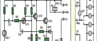
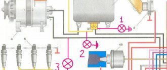
Electrical diagram of the T-40 tractor with a starter: 1 - turn and position indicator lamp; 2 — headlight; 3 — connecting panel; 4— sound signal; 5 — cabin ceiling; 6 — lamp and fan switch; 7 - fan; 8 — windshield wiper; 9 — oil temperature indicator sensor; 10 - generator; 11 — glow plug; 12 — “mass” switch; 13 - battery; 14 — starter; 15 — starter relay; 16 — indicator lamp for direction indicators; 17 — direction indicator switch; 18 - central light switch; 19 — headlight light switch; 20 — high beam warning lamp; 21 — signal switch; 22 — control lamp of the “ground” switch; 23—oil temperature indicator; 24 — diesel start blocking switch when the gear is engaged; 25 — control element; 26 - portable lamp; 27 — portable lamp socket; 28 - additional resistance; 29 — glow plug and starter switch; 30 - current indicator; 31 — “stop” switch; 32 — rear headlight switch; 33 — instrument panel lighting lamps; 34 — direction indicator breaker; 35 - fuse; 36 — indicator lamp for directions, dimensions and brake signal; 37 — taillight; 38 — plug socket; 39 — license plate lamp. Designation of wire colors in the diagram: B - white; G - blue (blue); F - yellow; Z—green; K - red; Kch - brown; F - purple; H - black. Next to the color designation, the numbers indicate the wire cross-section. Wire cross-sections not indicated in the diagram are 0.75 mm².
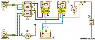
Electrical diagram of the T-40 tractor with a starting unit: 1 - turn signal and position indicator lamp; 2 — headlight; 3 — connecting panel; 4 — sound signal; 5 — cabin ceiling; 6 — lamp and fan switch; 7 - fan; 8 — windshield wiper; 9 — oil temperature indicator sensor; 10 - generator; 11 — spark plug; 12 — glow plug; 13 — “mass” switch; 14 - battery; 15 — starter of the starting unit; 16 - magneto; 17— indicator lamp for direction indicators; 18 — direction indicator switch; 19 — central light switch; 20 — headlight light switch; 21 — high beam indicator lamp; 22 — signal switch; 23 — control lamp of the “ground” switch; 24 — oil temperature indicator; 25 — starting unit stop switch; 26 — diesel start blocking switch when the gear is engaged; 27—control element; 28 - portable lamp; 29 — portable lamp socket; 30 — glow plug switch; 31 - additional resistance; 32 — starter switch of the starting unit; 33 - current indicator; 34 — rear headlight switch; 35 — instrument panel lighting lamp; 36 — direction indicator breaker; 37 - fuse; 38 — “stop” switch; 39 — lamp-indicator of directions, dimensions and brake signal; 40 — taillight; 41 — plug socket; 42 — license plate light. Wire color code in the diagram above.
The central switch is necessary to turn on the side lights and tractor lighting. The front lights are used to indicate the dimensions of the tractor and provide turn signals, the rear lights serve as indicators of dimensions, as well as turns and brake signals.
The headlights together with the lanterns are mounted on a single bracket, fixed to the front beam of the tractor. Rear lights and reflectors are installed on the rear wheel fenders, reflecting light from the headlights of vehicles behind.
To start the engine, the T-40 tractor can be equipped with a starting unit, a starter switch and a button to turn it off. There is a switch in the gearbox housing that prevents the engine from starting when the gear is engaged.
A ball roll indicator is connected to the electrical circuit of the T-40 ANM tractor.
Source
Generator MTZ-80: Connection diagram and fault prevention
Main rules for inspecting the MTZ-80 generator. Generator connection diagram.
In almost any vehicle or work vehicle on wheels, there are two power sources - a battery and a generator. We are not interested in cars, but the MTZ generator is very interesting, and that is what we will consider in detail.
Like absolutely any generator, a tractor generator strictly adheres to the same goals - converting one type of energy into another. Specifically, mechanical to electrical, which successfully performs from the rotation of the crankshaft, as on other equipment.
Device, diagrams, repair
Generator of the T-40 tractor. Alternator diagram and belt size
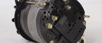
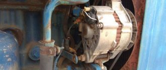
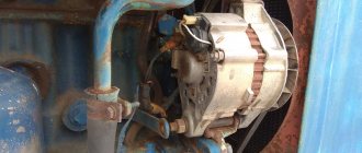
The generator of the T-40 tractor is used to power all consumers with electric current, as well as to recharge batteries. The generator is designed as a non-contact three-phase same-pole electric machine, equipped with one-way electromagnetic excitation, a Ya112B voltage regulator and a built-in BPV-23-50 rectifier unit.
On the back cover of the generator there are terminals “+” and “D” for connecting electrical consumers and devices, as well as a switch for seasonal voltage adjustment. The generator operates in parallel with the battery and serves to recharge it.
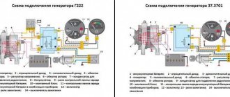
T-40 tractor generator: 1 - seasonal adjustment screw (winter-summer switch); 2 - voltage regulator; 3 — back cover; 4 - stator; 5 — front cover; 6 — fan impeller; 7 - pulley.
Generator specifications
| Rated voltage, V | 12 |
| Rated current, A | 13 |
| The number of revolutions of the generator armature at which a voltage of 12.5 V is achieved at a load current of zero | 2100 |
| The number of revolutions of the generator armature at which a voltage of 12.5 V is reached at current | 2500 |
| No-load current when the generator is operating in engine mode and the voltage at the terminals is 12 V in amperes | 7 |
| Brand of brushes | EG-13 |
| Brush size, mm | 6.5x16.2x21 |
| Pressure force on brushes of brush springs, kg | 0,6-0,8 |
| Armature rotation direction | right |
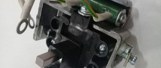
T-40 tractor generator diagram: 1 - lamp; 2 — back cover; 3 - stator; 4 — front cover; 5 - rectifier block; 6 — fan impeller; 7 - pulley.
Exploitation
To prevent failure of the generator, equipped with a built-in integral voltage regulator, when performing welding work on the tractor, turn off the “ground” switch in advance.
To increase the service life of the generator, it is recommended to adhere to the following rules:
1. It is prohibited to connect the battery terminals with reverse polarity - this will lead to failure of the voltage regulator and generator;
2. Do not under any circumstances start the engine from an external source with a voltage exceeding 13 V;
3. Do not wash the generator with gasoline, diesel fuel or solutions containing degreasers, or dry it at temperatures exceeding 85 ºC;
4. It is prohibited to check the generator for serviceability by shorting the terminals to ground and the terminals of the voltage regulator to each other;
5. It is prohibited to check the presence of electric current by shorting to ground when the battery is removed.
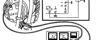
The serviceability of the T-40 tractor generator can be checked using the ground switch indicator lamp located on the left of the instrument panel. The warning light comes on after turning on the ground before starting the engine. If the generator is working properly, the warning light will go out after the engine starts.
T-40 tractor generator belt drive: 1 — generator bracket; 2 — tension bar; 3, 6, 10 — nuts; 4 — generator pulley; 5 - V-belt; 7, 9 — bolts; 8 — locking plate; 11 - hairpin.
The T-40 generator belt is used to convert rotation from the engine to the generator into electrical energy. The alternator belt size is 8.5x8-1280.
Generator maintenance and repair
Generator maintenance involves infrequently checking the contact connections and the reliability of the generator mounting.
After every 120 hours of operation, check the tension of the fan belt; if necessary, tighten the belt by unscrewing the nut and moving the generator towards you. The generator belt tension is considered normal when the belt deflection between the crankshaft and the fan pulley is 15-22 mm if you press it with a force of 4 kgf.
After every 960 hours of tractor operation, check:
1. Ease and correct movement of brushes in the brush holder. If you notice that the brush is stuck, fix it.
2. Replace worn brushes up to 14 mm with new ones. Rub the new brushes onto the commutator using sandpaper. After grinding in, blow out the surface of the commutator and the internal cavity of the generator. Using a dynamometer, measure the pressure of the brush springs (0.6-08 kgf).
3. If there is burnt on the collector, wipe it with a clean rag soaked in gasoline. You should not sand the polish, as it improves the performance of the brushes. If the burn cannot be removed, clean the collector with fine sandpaper.
4. In case of large burnout or burning of the commutator, remove the generator from the engine and have it repaired by qualified specialists.
The bearings must be lubricated every 240 hours. From the moment of operation, the generator does not need to add lubricant during the first 1440 hours.
T-40 engine
Engine structure of the T-40 tractor: piston, crankshaft, cylinders
Power transmission
Design and operation of the power transmission of the T-40 tractor
Supply system
Design of the T-40 tractor power system: nozzles, fuel injection pump, etc.
Electrical equipment
Electrical equipment T-40: diagrams and device.
Hydraulics
Hydraulic system: malfunctions and repairs.
Tractor T-40 - design, operation and repair
Source
Frequent problems and their diagnosis
1 So, the control light does not go out, what should you do? Do not panic and immediately check the belt tension. If it is in order, then you need to check the contacts for oxides. If performance is not restored after cleaning, you need to check the output voltage. It should not be lower than 12.5 volts.
2 If you hear extraneous noise and knocking during operation, the problem is the loosening of the pulley fixing nut. However, bearing failure is also possible. Diagnosed by routine disassembly. The bearing will noticeably crunch when worn and will need to be replaced. The nut can be lubricated with thread sealant and tightened more tightly.
The main thing is that the fit on the pulley is not disturbed. You can notice a broken seat by the free movement of the nut. In this case, it needs to be replaced.
3 Under no circumstances should the bearing be knocked out. The shaft can be damaged, and this is a major repair. A special puller is required.
Otherwise, other generator breakdowns rarely occur on MTZ tractors.
Device, diagrams, repair
Electrical equipment of the T-40 tractor and its diagram
The electrical equipment of the T-40 tractor is designed to start the engine and operate safely at night when performing transport or agricultural work. The electrical equipment is implemented using a single-wire system, in which the metal parts of the tractor (“ground”) serve as the negative wire. The rated voltage in the tractor electrical system is 12 V. Electric current sources are connected to ground by negative terminals.
Electrical equipment T-40 consists of the following units and devices:
1. A DC generator equipped with a relay regulator and batteries, which are a source of electric current.
2. A starter with a relay and a starter switch that functions as an engine starting device.
3. Direction indicators, side indicators, rear and front headlights, dome light, brake light, license plate light, fan belt break warning light, as well as a portable lamp are used for light signaling and lighting.
4. An ammeter that displays the strength of the discharge or charging current.
5. Sound signal equipped with a switch.
6. Connecting panels and wires, ground switch and fuse.
Electrical diagram of the T-40 tractor with a starter: 1 - turn and position indicator lamp; 2 — headlight; 3 — connecting panel; 4— sound signal; 5 — cabin ceiling; 6 — lamp and fan switch; 7 - fan; 8 — windshield wiper; 9 — oil temperature indicator sensor; 10 - generator; 11 — glow plug; 12 — “mass” switch; 13 - battery; 14 — starter; 15 — starter relay; 16 — indicator lamp for direction indicators; 17 — direction indicator switch; 18 - central light switch; 19 — headlight light switch; 20 — high beam warning lamp; 21 — signal switch; 22 — control lamp of the “ground” switch; 23—oil temperature indicator; 24 — diesel start blocking switch when the gear is engaged; 25 — control element; 26 - portable lamp; 27 — portable lamp socket; 28 - additional resistance; 29 — glow plug and starter switch; 30 - current indicator; 31 — “stop” switch; 32 — rear headlight switch; 33 — instrument panel lighting lamps; 34 — direction indicator breaker; 35 - fuse; 36 — indicator lamp for directions, dimensions and brake signal; 37 — taillight; 38 — plug socket; 39 — license plate lamp. Designation of wire colors in the diagram: B - white; G - blue (blue); F - yellow; Z—green; K - red; Kch - brown; F - purple; H - black. Next to the color designation, the numbers indicate the wire cross-section. Wire cross-sections not indicated in the diagram are 0.75 mm².
Electrical diagram of the T-40 tractor with a starting unit: 1 - turn signal and position indicator lamp; 2 — headlight; 3 — connecting panel; 4 — sound signal; 5 — cabin ceiling; 6 — lamp and fan switch; 7 - fan; 8 — windshield wiper; 9 — oil temperature indicator sensor; 10 - generator; 11 — spark plug; 12 — glow plug; 13 — “mass” switch; 14 - battery; 15 — starter of the starting unit; 16 - magneto; 17— indicator lamp for direction indicators; 18 — direction indicator switch; 19 — central light switch; 20 — headlight light switch; 21 — high beam indicator lamp; 22 — signal switch; 23 — control lamp of the “ground” switch; 24 — oil temperature indicator; 25 — starting unit stop switch; 26 — diesel start blocking switch when the gear is engaged; 27—control element; 28 - portable lamp; 29 — portable lamp socket; 30 — glow plug switch; 31 - additional resistance; 32 — starter switch of the starting unit; 33 - current indicator; 34 — rear headlight switch; 35 — instrument panel lighting lamp; 36 — direction indicator breaker; 37 - fuse; 38 — “stop” switch; 39 — lamp-indicator of directions, dimensions and brake signal; 40 — taillight; 41 — plug socket; 42 — license plate light. Wire color code in the diagram above.
The central switch is necessary to turn on the side lights and tractor lighting. The front lights are used to indicate the dimensions of the tractor and provide turn signals, the rear lights serve as indicators of dimensions, as well as turns and brake signals.
Tractor T-40, T-40A. Tractor electrical equipment
The electrical equipment installed on the T40 and T40A tractors is intended for starting the engine and normal operation of the tractor and agricultural unit at night, both when performing agricultural work and when using the tractor for transport work. The tractor's electrical equipment is connected via a single-wire wiring system, in which the metal parts (“Ground”) of the tractor itself serve as the negative drive.
Each source and each consumer of electrical energy is connected by one pole to the “Ground”. Voltage (nominal) in the electrical system is $12.
The tractor electrical system includes the following devices and units (see diagram, Fig. 74):
1. DC generator 3 with relay regulator 9 and batteries 29, which are a source of electrical energy.
2. Starter 34 with relay 2 and starter switch 30, which serves as an engine starting device.
3. Headlights 1, rear lights 21, double-sided lights 23 - direction indicators, side indicators, brake lights, license plate light 22, ceiling lamp 24, warning lamp for broken fan belt 7, as well as a portable lamp are used for lighting and light signaling.
4. Ammeter 11, showing the amount of charging or discharge current.
5. Sound signal 6 with switch 13.
6. Connecting panels 5, ground switch 28, fuse and connecting wires.
The tractor can be equipped with a starting motor when, instead of the main starter, in addition to the listed equipment, a starting motor starter switch and a starting motor stop button are installed.
The electrical diagram of a tractor with a starting motor is shown in Fig. 75.
Rice. 74. Electrical diagram of a tractor equipped with a starter:
1 — headlights; 2 - starter relay; 3 - generator; 4 — temperature indicator sensor; 5 - connecting panels: 6 - sound signal; 7 - warning lamp for broken fan belt; 8 — oil temperature indicator; 9 — relay-regulator; 10 — portable lamp socket; II - ammeter; 12 - fuse; 13 —* signal switch; 14 — direction indicator switch; 15 — “Stop” switch; !6 — rotation signalizer; !7 — headlight switch; 18 — lamp and fan switch; 19 — plug socket; 20 - fan; 21 — rear lights; 22 — license plate lamp; 23 — double-sided lantern; 24 — cabin ceiling; 25 — instrument panel lighting lamp; 26 — switch for the instrument panel lighting lamp; 27 — light switch for rear headlights and side lights; 28 — “Mass” switch; 29 — battery; 30 — glow plug and starter switch; 31 - additional resistance; 32 — glow plug control element; 33 - glow plug; 34 - starter.
Designation of wire colors in the diagram: B - white; K - red; G - blue; 3 - green; F - yellow; Cor. brown; F - purple; H - black Next to the color designation, the numbers indicate the wire cross-section.
Rice. 75. Electrical diagram of a tractor equipped with a starting motor: 1 - front headlights; 2 - starter relay; 3 - warning lamp for broken fan belt; 4 - generator; 5 — temperature indicator sensor; 6 — connecting panels; 7 — oil temperature indicator; 8 — instrument panel lighting lamp; 9 - switch for instrument panel lighting; 10— fuse; 11 — portable lamp socket; 12 — cabin ceiling; 13 — lamp and fan switch; 14 - fan; !5 — direction indicator switch; 16 - turn signal; 17 — front light switch * fa^>; 18 — switch for rear headlights and side lights; 19 — “Stop” switch; 20 — plug socket; 21 double-sided lanterns; 22— rear lights; 23 — license plate lamp; 24 — “Mass” switch; 25 - battery; 26 — glow plug; 27 — signal switch; 28 — glow plug control element; 29 — sound signal; 30 - additional resistance; 31 — starting motor starter; 32 — spark plug; 33 — starting motor stop switch; 34 — starting motor starter switch; 35 - ammeter; 36 — relay-regulator; 37 — glow plug and starter switch; 38 - magneto. Designation of wire colors in the diagram: B - white; K - red; G - blue; 3 - green; F - yellow; Cor. - brown; F - purple; H - black. Next to the color designation, the numbers indicate the wire cross-section.
What generators were installed at MTZ before and what has changed now
The generator on tractors, as well as on other self-propelled machines, is designed to convert mechanical energy from the rotation of the engine crankshaft into electrical energy to power the on-board power supply of the tractor and to charge the battery. Several types of generators were installed on MTZ tractors, depending on the configuration and year of manufacture, but they are all similar in design. These are three-phase electromechanical AC machines.
The electrical on-board network and the tractor battery operate on direct current, therefore, together with the generator, a rectifier is installed that converts alternating current into direct current, as well as a relay regulator - a device that keeps the voltage supplied by the generator within 14 - 15 volts at 12 volt on-board network, or within 28 volts if the on-board network is 24 volts, regardless of the rotation speed and the number of simultaneously switched on devices.
The current arises in the generator due to the interaction of the electric magnetic fields of the rotating rotor and the stationary stator. The initial moment of occurrence of the magnetic field is called “excitation”. The generators that were installed on MTZ tractors of different years of production have a separate excitation winding, which is supplied with power from the battery when the mass or ignition is turned on. However, older tractor models did not have a starter and battery in all configurations. The diesel engine was started using a starting engine, which, in turn, was started manually by the machine operator. On such a tractor it was not necessary to have a battery. In such configurations, the excitation problem was solved by using permanent magnet generators instead of excitation windings, which did not require current from the battery to generate an electromagnetic field. An example is G 46.3701, which was widely used at that time. Modern tractors are always equipped with starters and batteries, so the need to install self-exciting models has disappeared.
Operation of the Generator on the T-40
To avoid damage to the generator, with an integrated voltage regulator installed, the “ground” is turned off before performing welding work.
To extend the life of the generator, the following recommendations must be followed:
- It is strictly forbidden to connect battery terminals in reverse polarity.
- You cannot start the engine from a third-party power source with a voltage greater than 13 V.
- It is prohibited to wash the tractor generator in gasoline, diesel fuel or other solutions containing degreasers, or to dry it at temperatures above 85C.
- It is impossible to check the serviceability of the generator by connecting the ground terminals and voltage regulators.
- It is prohibited to check the presence of current by shorting to ground when there is no battery in the tractor.
Design of generators for MTZ, connection diagram and repair
The tractor generator converts mechanical rotational energy into electrical energy and provides power to the electrical equipment of the machine, including recharging starting batteries with a voltage of 12 or 24 volts. MTZ 80(82) tractors of early modifications were equipped with self-excited three-phase alternating current generators G304, G305 and G306 of Soviet production with an output voltage of 14 volts and a power of 400 W. Additional letters in the abbreviation of the modifications of the above generators indicate differences in the stator winding data and have a similar unified design with the same technical characteristics. G 304 and G305 included two fixed excitation windings for generating energy during left and right rotation, G 306 with one excitation winding only for right rotation. A more modern version of tractor generators has a similar design with the marking 46.3701.
Maintenance of the generator on the T-40 tractor
After 120 hours of operation, it is necessary to check the degree of belt tension and, if necessary, tighten it. To do this, you need to unscrew the nut and move the generator towards you. Belt tension is considered normal when the deflection between the crankshaft and the pulley is 15–23 mm.
After 960 hours of operation it is necessary to perform:
- Check for any jamming in the movement of the brushes, which, if detected, must be eliminated urgently.
- Replacement of worn brushes up to 15 mm. New brushes are ground to the commutator using sandpaper. After this, the surface and internal cavity of the collector are purged.
- If there is carbon deposits on the manifold, remove it with a rag soaked in gasoline. If carbon deposits cannot be removed in this way, then it is necessary to use fine sandpaper.
- 4. If there are signs of burning on the collector, it is necessary to remove it and send it to highly qualified specialists for repair. After every 240 hours of operation, the bearings must be lubricated. Once in use, the generator does not require additional lubrication for 1440 hours. Page Contents