- home
- Media center
- Articles
- Kamaz speed sensor circuit
Menu
- News
- Articles
- Video materials
- Photo materials
- Publication in the media
- 3D tour
16.04.2019
Recently, all mechanisms of modern cars are fully automated. This trend has overtaken speed sensors, which have become electronic and, accordingly, have received wider functionality and a more complex structure. The sensor measures the speed of the vehicle while driving. This unit is very important, because it is the driving activity mode that allows you to control the car on the road. The speed of the truck must be controlled doubly carefully, because many aspects of the dynamics of movement are related specifically to the speed limit. For example, a passenger car “goes” stably, increasing or decreasing performance either through a gearbox or automatic transmission (generally independently without human intervention), so the smoothness of movement is determined automatically. Of course, many tractors are equipped with automatic transmissions, but the complexity of freight transportation and large tonnages determine the need to use high and low gears, which can be switched at a certain speed. A working sensor transmits data to the speedometer, from which the driver reads information.
Technical characteristics of the ZF 9S 1310 series gearbox
| Model | 9 S 1110 TD/TO | 9 S 1310 TO |
| Input torque max, Nm 1) | 1100 | 1300 |
| Gear ratios | ||
| Forward travel | 12,73 – 1,00 / 9,48 – 0,75 | 9,48 – 0,75 |
| Reverse | 12,04 / 8,97 | 8,97 |
| Electronic tachometer | Z=8 | |
| Installation 2) | Horizontally on the left, lever withdrawal for left. or right. steering | |
| Gear shift | ||
| Unit with 4 gears | Downshift and reverse with cam. couplings | |
| Demultiplier | All other transmissions are synchronized | |
| Gear shift drive | ||
| Unit with 4 gears | Gear shift mechanism with horizontal rotary shaft 3) with shift pattern double H and cascade H | |
| Demultiplier | Double H: shifting is pneumatically controlled and automatic 4) Cascade H: shifting via preselector on the gear lever | |
| Weight (without additional equipment) approx., kg | 190 | |
| Oil quantity | ||
| For standard installation 5) approx. l | Approximately 9.0 dm 3 | |
| Oil type | According to the current lubricant specification ZF TE-ML 02 | |
To ensure reliable operation of the gearbox, the oil change intervals specified in the specifications must be observed!
Prevent oil from entering the ground, groundwater or sewer system. Collect any leaking oil in a suitable container and dispose of it in accordance with environmental regulations.
Basically: change the oil after a long trip, while the gear oil is still at operating temperature and consistency.
Touching the gearbox or transmission oil can cause burns!
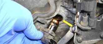
Unscrew the oil drain plugs on the gearbox and drain the used oil into a suitable container.
Clean the oil drain plugs, replace the O-ring and tighten to the specified torque.
Clean the screw plug. Clean the oil drain plug with magnetic filter, replace the O-ring and tighten to the specified torque.
Fill the oil through the filling hole.
The oil fill level is correct if it reaches the bottom edge of the fill hole or if oil is already flowing out of the fill hole.
To guarantee a certain service life and performance of the synchronizers, perfect disengagement of the clutch is an indispensable condition. The same applies to the inclusion of clutch-dependent power take-off mechanisms.
Perfect clutch disengagement can be checked as follows:
Let the engine idle and press the clutch.
No later than 20 seconds later (depending on the flywheel mass and temperature), slowly engage reverse gear.
If at the same time a “grinding” of the gearing of the gear shift mechanism is heard (grinding of the clutch cams), then it is necessary to adjust or check the clutch.
Transmission oil heats up when the vehicle is moving. As a result, excess pressure forms, which must be constantly released through the air valve.
Make sure that the breather is working properly at all times. The breather must be clean and the cap must be removed. Do not spray directly with high-pressure water (water in the gearbox is a risk of corrosion).
Vehicles that require frequent cleaning due to operating conditions must be equipped with a breather with a hose. These are, for example, milk tankers, concrete trucks, etc.
The hose must be laid without kinks or loops. The end of the hose must extend into a dry space (such as the engine compartment or frame cavity).
Ensure that the valve is in good working order. The air valve must be clean and not covered with a plastic cap.
Compressor unit maintenance
Condensation forms in every compressor unit. To prevent condensation, rust and other contaminants from the air receiver from entering the valves and working cylinders, regular maintenance of the compressor unit is required. The air receiver must be dehydrated weekly, daily in winter.
Along with the air receiver, the compressed air filter with water separator must also be dehydrated if it does not work automatically. Please also observe the vehicle manufacturer's specifications.
Source
Multiplier, gear shift pattern double H
The gear shift pattern is divided into 5 adjacent rows. Rows 3/4 and 5/6 each have one spring-loaded neutral position. The different spring pressures make possible good orientation in the gearshift pattern. Pneumatic switching of the range-multiplier occurs automatically when switching from row 3/4 to row 5/6 or vice versa.
ZF shift pattern double H and gear lever
Demultiplier, cascade gear shift circuit H
The gear shift pattern is made with three rows lying next to each other. The 3/4 or 7/8 row has a spring-loaded neutral position. Pneumatic switching of the range from row 3/4 to row 5/6 or vice versa is carried out by a preselector on the gear shift lever.
ZF shift diagram cascade H and gear lever
The range control consists of a switching valve (35) and a double-acting pneumatic cylinder (34) installed in the gearbox.
Buy spare parts from us:
Source
Why does not it work
If the speedometer fails or does not work, the reasons may be as follows:
- The gears of the worm gear of the device are made of plastic. Since the material is fragile, this can cause the gears to break.
- The cable broke off where it connects to the speed system, which is screwed into the gearbox.
- The sensor contacts have oxidized or the power supply wire has broken. At the same time, the power is checked using a multimeter.
- There was a breakdown of the electronic part of the device located in the panel.
- There were distortions in the device readings. Most often this is due to instrument calibration, which is difficult to perform.
Speed is measured by the rotation of one axle of the final drive, and when turning, the wheel located on the inner radius travels a shorter distance than the outer one.
But the main reason for the inaccuracy of the data is the size of the wheels. The larger the wheel, the greater the distance the machine will travel in 1 revolution of the shaft.
Distinctive features of the ZF box
The ZF transmission system is found primarily on trucks. It provides the vehicle with better traction and dynamic characteristics. The ZF-Ecomid gearbox is a synchronized gearbox that provides quick gear changes. Thanks to it, there is a reduced load on the engine, as a result, the movement of vehicles becomes smoother.
What does the ZF 9S1310 box include? This unit is a 4-stage gearbox, which has a reduced speed. There is a planetary multiplier, which includes a double-acting pneumatic cylinder. The gear shift pattern is “double H”. It should be noted that there is an electronic speedometer and tachometer. The crankcase cover is made of aluminum.
The ZF 9s1310 gearbox helps reduce the workload on the driver. It has the following gear ratios - 9.47-0.74.
Among the additional advantages it is worth highlighting:
- speed of gear changes;
- low noise level during operation;
- extended transmission fluid change interval.
This box is in most cases installed on KamAZ vehicles.
Driving this vehicle is not difficult. First, you should tighten the parking brake, move the handle to the “N” position, after which the engine starts, and 1st gear is engaged. Finally, the parking brake and clutch are released.
Due to its functional features, ZF KamAZ is in good demand. The box is easy to repair. Timely maintenance of a vehicle with a ZF gearbox helps to extend its performance beyond the warranty period.
Possible breakdowns and repair instructions
The ZF 9s1310 gearbox can be found on KamAZ-65115, which is distinguished by high reliability indicators. The box allows you to improve the driving characteristics of the vehicle. Thanks to it, the efficiency of using engine power significantly increases. The pneumatic drive of the range multiplier is reliable. In addition to KamAZ 65115, this type of gearbox can be installed on models 65116, 53605. What problems can occur with the ZF gearbox?
One of the problems with the ZF gearbox is the difficulty of changing gears. It seems possible to eliminate this manifestation by adjusting the valve to which the divider is connected. Otherwise, the synchronizer may break. The valve should not show any dirt.
If the gearbox divider synchronizer breaks down, gear shifting becomes difficult. It is necessary to check the condition of the primary and secondary shafts and related mechanisms. This requires a special overhaul of the box. This procedure should be entrusted to professionals. Detected worn parts must be replaced.
Selecting transmission oil
One of the reasons for early failure of the transmission system is excess or lack of oil. The need to replace this fluid depends on the operating conditions of the vehicle. The interval is 60,000 km.
How to check the oil level? To perform this procedure, you need to unscrew the filler plug. In its normal position it should reach the bottom edge of the inspection hole. It is worth changing the oil when the engine is warm. Thanks to this, optimal viscosity will be observed, and the fluid will quickly drain from the gearbox.
For ZF 9S1310, lubricants with TE-ML 02 approval must be used. The ZF 9 box requires approximately 9 liters. Oils you can use: ZIC GFT 75W-90, Petronas TUTELA OTZ 80W-90.
Thus, the ZF 9s1310 gearbox is found on medium-duty vehicles. The popularity of this transmission system is explained by the fact that it is distinguished by reliability. It should be noted the ease of gear shifting. This adds to driving comfort. It is recommended to purchase ZF KamAZ gearboxes from companies that provide a guarantee for their products. This box ensures high efficiency of the machine.
Source
Kamaz zf gearbox sensor, gearbox speed sensor
On vehicles, depending on models and configurations, gearboxes of models 141, 142, 144, 152, 154, ZF-6S1000, ZF-9S1310, ZF-9S109 f. “ZF” (Germany).
The 141 model's transmission is a manual, three-way, five-speed with synchronizers in second, third, fourth and fifth gears.
The gearbox of models 142, 144 is mechanical, five-speed, with synchronizers in second, third, fourth and fifth gears, consists of a main gearbox; models 152, 154 - mechanical, ten-speed, consists of a main five-stage gearbox and a two-stage divider located in front of the main box.
The transmission of the ZF-6S1000 model is mechanical, six-speed with synchronizers in first, second, third, fourth, fifth, sixth gears.
The transmission of models ZF-9S109, ZF-9S1310 is mechanical, nine-speed, includes a main four-speed gearbox and a planetary range, located behind the main gearbox, and has an additional low gear.
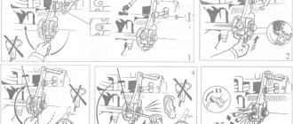
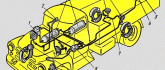
Drive adjustment: 1 – lock nut; 2 – set screw; 3 – bolt; 4 – adjusting flange; 5 – coupling bolt; 6 – traction; 7 – rod.
Gear ratios
L – lowest gear in the divider; S – highest gear in the divider; R – reverse; C – low gear
Adjust the remote drive for controlling the gear shift mechanism in transmissions of models 142, 152 (with engines of models 7403-260, 740.11-240, 740.13-260) with the gear shift lever in neutral position in the following order:
– loosen the coupling bolts 5 (see Fig. Adjusting the drive) and, having unscrewed the bolts 3, ensure clearance in the connection by screwing the adjusting flange 4 onto the rod 6 one or two turns;
– having loosened the lock nut 1, screw in the set screw 2, thereby stopping the movement of the rod 7;
– loosen locknut 1, screw in set screw 2 (see Fig. Set screw and lock nut). thereby stopping the movement of the gear shift lever;
Set screw and lock nut: 1 – lock nut; 2 – installation screw.
– by rotating, move the adjusting flange 4 along the thread (see Fig. Adjusting the drive) until it makes contact over the entire surface with the flange of the rod 7. Install bolts 3 and tighten the tightening bolts 5;
– unscrew the set screw 2 by 21 mm and lock it with a lock nut;
– turn out the set screw 2 (see Fig. Set screw and lock nut) by 31 mm and lock it with the lock nut.
Adjustment of the remote (central) control drive of transmissions of models 152 (with engines of models 740.30-260, 740.31-240) and 154 with the possibility of using a power take-off on the upper hatch and on the flywheel housing (see Fig. Drive (central) control of the shift mechanism gears of the model 152 gearbox and the (central) drive for controlling the gearshift mechanism of the model 154 gearbox) with the gearshift lever in neutral position in the following order:
– loosen nuts 14, 15 and 16;
– fix rod 4 in the neutral position by screwing in screw 5;
– fix the rod 3 with the technological rod 6 in the support of the gear shift lever 1;
– screwing the adjusting flange 7 until it touches the entire plane with the flange of the rod 4 (for a gearbox mod. 154, ensure dimension C is equal to 30 ± 1 mm), connect the rod 8 to the rod 4 with bolts 9;
– fasten the adjusting flange 7 to the rod 8 with bolts 10, tightening them to a torque of 50...70 Nm (for gearbox mod. 152), 75...95 Nm (for gearbox mod. 154);
– for gearbox mod. 154: screw the shank 11 into the rod 3, setting it perpendicular to the inclined plane of the lever 12 and aligning the axis of the conical pin with the axis of the hole in the lever 12;
– by rotating part M of the reaction rod 13, install lever 1 and rod 3 in a vertical plane;
– tighten nuts 14, 15 and 16;
– screw screw 5 to the specified length (21±1 mm) and lock it with a nut;
– remove technological rod 6.
Drive (central) for controlling the gear shift mechanism of the model 152 gearbox: 1 – gear shift lever support; 2 – rear thrust; 4 – traction; 5 – transverse thrust; 16 – adjusting coupling flange; 23.25 – bolts; 46 – nut; F – rod; P – technological rod; And - screw.
Drive (central) for controlling the gear shift mechanism of the model 154 gearbox: 1 - gear shift lever support; 2 – lever, 3 – rod; 4 – rod; 5 – screw; 6 – technological rod; 7 – adjusting coupling flange; 8 – intermediate thrust; 9 – bolt, 10 – bolt, 11 – shank; 12 – lever; 13 – jet thrust; 14, 15, 16 – nuts
Check the installation size of the gear divider valve stop for the model 152 transmission (except for transmissions with engines models 740.30-260, 740.31-240 with side drive) by moving the stop 4 of the valve stem. After setting the required value A = 20.5 ± 0.5 (see Fig. Clutch drive), secure the stop with nuts, lock the nuts with bend washers.
Check the stroke of the gear divider lever for gearboxes of models 152, 154 when there is compressed air in the brake pneumatic drive. To measure:
Clutch drive: 1 – dust fuse; 2 – cover; 3 – rod limiter; 4 – stop (flag) of the valve stem.
– remove cover 1 (see Fig. Divider mechanism) of the inspection hatch of the gear divider switching mechanism;
– press the clutch pedal all the way;
– by moving the gear divider control switch from the upper position to the lower position or vice versa, measure the stroke of the lever in the center of the hole. The normal stroke is 16.5…19.0 mm.
KamAZ speed sensor – Where is it located and connection diagram
Speed sensor: at the heart of the safety and comfort of a modern car
In recent decades, mechanical automobile speedometers have been replaced by electronic speed measurement systems, in which speed sensors play an important role. Read everything about modern speed sensors, their types, design and operation, as well as their correct selection and replacement in this article.
electrical voltage occurs. The DSA is based on a Hall chip, into which a plate (usually made of permalloy) and an amplifier circuit are already integrated. In the sensors, the microcircuit and magnet remain stationary, and the magnetic field changes due to a rotating “curtain” - a ring with slots. The ring is connected to a drive cable or shaft, from which it receives rotation. The output signal from the DSA is supplied to the speedometer or controller through a standard connector, through which power is supplied to the Hall chip. Non-contact sensors based on the Hall effect Scheme of operation of a non-contact speed sensor Non-contact DSA is based on the same effect, but it has no moving parts - instead, a rotor or pulse disk with magnetized sections is located on the shaft of the unit (gearbox, axle gearbox). There is a small gap between the sensitive part of the sensor (with the Hall microcircuit) and the rotor; when the rotor rotates in the microcircuit, it is formed. All articles
The parts data presented on this page is for informational purposes only.
Source
ABOUT KAMAZ checkpoint. SCHEME, DOUBLE SQUEEZE AND REGASING.
Device
The speedometer on KamAZ is a device for measuring the speed of a vehicle. The device connects to a speed sensor and a topographer.
Analog can be:
- Pointer - speed is shown by moving the arrow across the dial.
- Tape - the location of the tape on the horizontal scale shows the speed.
- Drum - the indicator is placed on a drum that rotates in proportion to the change in speed.
A mechanical dial meter is installed on many machines.
Analog meter device:
- Worm unit, which is installed in the gearbox.
- A gear that rotates together with the gearbox shaft. This makes it possible to calculate the rotation speed of the drive and wheels.
- The wire that runs from the worm assembly to the instrument panel.
- Magnetic element.
- A metal plate attached to the arrow.
- Scale.
- Spring.
An accompanying element of the device is a counter, which determines the length of the path traveled and is connected to the cable via a worm gear.
In the electronic device, there is no mechanical connection between the data on the instrument panel and the transmission output shaft. The device is:
- Optoelectronic, in which there is a high-speed part with a cable, and the speed data is determined by photointerrupter pulses.
- Bestrosov, in which a magnet is installed, rotating in place with the gearbox shaft. Changes in the magnetic field are converted into pulses by the bridge circuit.
A popular meter that operates using the Hall effect. Changes in output voltage are proportional to the rotation speed of the disk. The frequency of the voltage pulses allows you to determine the speed of the machine.
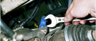
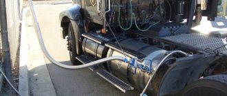
Where is the speed sensor located?
In most cases, the sensors are located at the gearbox and are connected by a special drive to the speedometer, the data of which is read to determine speed and mileage.
Thus, it is advisable to find functional units taking into account the layout of a specific KamAZ model and the specifics of the technical system. The devices have different designs, since the influence of the location of the unit is noted.
Contact sensors are considered less reliable due to the interaction of spare parts and constant rotation. However, such devices are often used, as they are installed instead of a mechanical speedometer drive and allow you to modernize brake systems. Contact models are characterized by optimal reliability.
Sometimes on KamAZ, speed sensors can be installed without direct contact with the rotating shaft. To measure speed, a drive disk or rotor is often used, since this device is auxiliary. Contactless models are becoming in demand, as a result of which they are often installed on modern KamAZ models.
The KamAZ zf speed sensor is also popular, as it is created according to modern standards. The package includes a modern transfer case that increases reliability. A working unit allows you to find out the exact technical characteristics of the vehicle. Over the past few years, such devices have been successfully used on domestic vehicles, including KamAZ. Motorists remain satisfied, because with proper regular maintenance, additional benefits are noted, or rather, economical fuel consumption and a minimal amount of substances released into the air.
Recently they have also offered KamAZ with a Euro 3 engine and a reliable speed sensor. This modification has a specific technical design, so it is advisable to contact professionals who know where all the devices can be located and how best to carry out repairs. When studying the reviews of motorists, one can understand that the KamAZ Euro is a confirmation of the modernization of the car, which ceases to be popular and begins to meet European standards.
Fact! Any sensors work only on physical principles. Contact devices usually use the Hall effect and magnetoresistive effect (MRE), optocouplers. Non-contact sensors most often operate on the Hall effect and much less frequently on MRE.
Location Features
Speed sensors have different locations in car mechanisms. However, Russian car manufacturers are distinguished by their stability, so the old-style Kamaz has almost identical components to the new-type Kamaz 5320.
- The most common option is to integrate the sensor into the speedometer operating system. The functionality is simple: measuring the current speed, transmitting data. Therefore, when the driver says “the speedometer does not work,” most likely the situation develops directly around a faulty sensor that incorrectly transmits signals.
- The injection, ignition, and other engine systems may contain a speed limiter to adjust the operating system of the internal combustion engine. As the driving dynamics change, the load on the motor changes accordingly. More modern tractors are designed in such a way that the increased load is adjusted by the speed limit. In this way, a balance is achieved between the driving characteristics of the tractor and the power.
- Modern cars can include this unit in alarm systems or other security units. Such a move perfectly helps to adjust the speed of movement for the driver. A striking example is cruise control. Modern Kamaz models also have cruise controls and limiters so that the driver can fully concentrate on the road.
- The rarest case is power steering or other enhanced comfort systems. Hydraulics have a strong influence on determining speed, so sometimes determining mechanisms are installed in this particular unit. However, the hydraulic system is only part of the main mechanism that allows the car to better hold the road, that is, it is auxiliary.
In short, just one component, having one functionality, can serve as part of completely different systems. Each is important in its own way, but transmitting data to the speedometer still remains the most popular task, common on eighty percent of modern domestic Kamaz tractors. New foreign trucks operate on more advanced systems, however, packed with electronics, they require constant technical professional maintenance, while the owner of a domestic truck can largely service the tractor independently.
DSA - an abbreviation for vehicle speed sensor - being a traditional speedometer drive, it is simply mounted inside the transmission, transfer case or drive axle gearbox, monitoring the speed of the secondary or intermediate shaft. The next step in the process is to transfer the data to the speed measurement controller.
Operating principle of the speed sensor
Most sensors operate on the Hall effect. To determine speed and mileage, frequency pulses are used, which are sent at a certain interval. Impulses arise when the wheels rotate, so the mechanics calculate the data and they are displayed on transport devices. Typically, up to 6 thousand signals are issued for every kilometer. The KamAZ Euro speed sensor is considered the most advanced, since it was created on the basis of modern standards and European experience in the automotive sector, and is distinguished by its information content and accuracy.
Contact sensors
The basis of such devices is a corresponding microcircuit with a special plate and an amplification circuit. The chip and magnet do not move. To change the magnetic field and read pulses, rings with special slots rotate. The presence of small connectors allows you to read indicators for display on devices. The old-style KamAZ 5320 speed sensor was made using this principle.
However, on domestic models, including 4308, 53504 (the name appeared on some modifications after the restyling of 44108), the technical system has been improved. You can also read about Separating the pads on a KamAZ - Correct installation of the pads.
Non-contact sensors
The device operates on the Hall effect, but the design is different. On the shaft of the unit (gearbox or axle gearbox) there is a rotor or impulse disk with areas that are magnetized. There is a gap between the Hall chip and the rotor, but pulse signals are successfully read through standard connectors. This KamAZ speed sensor circuit is considered reliable, since spare parts interact less with each other and unwanted mechanical influence is prevented.
How to wind the speedometer on a KamAZ
The KamAZ-6520 or KamAZ Euro speedometer is adjusted using special devices that allow you to adjust the device’s performance. If you need to rewind the device or change the device data, you can contact specialists. But there is a way to do it yourself.
KamAZ is equipped with a speedometer and odometer, showing the mileage of the vehicle, and has a generator and engine system. The generator is the sensor, the engine is the receiver. The speedometer receives a three-phase signal from the generator.
Possible malfunctions of the speed sensor
KamAZ 55102, 65115 often have device malfunctions, because such models have been produced for a long time and there are numerous used models on the domestic market. Malfunctions are manifested by problems with idle speed (the car may stall), corrosive changes in contacts.
The KamAZ gearbox and speed sensor must be replaced, otherwise the following problems may appear:
- lack of information about mileage and speed due to inoperative devices;
- malfunction of the engine (impaired idling speed, excessive fuel consumption, loss of power);
- serious problems with security systems.
Note! Be sure to use a sensor that was installed earlier or recommended by the car manufacturer. If the unit is incorrectly selected, it will not be possible to install it, switching between speeds will not occur correctly, or the technical data will not be read correctly.
How to connect
The speedometer connection diagram, calibration and pinout instructions are available in the operating instructions for the device. At KamAZ, during manufacturing, the device is configured and a seal is installed on it. The need for adjustment arises when replacing a sensor, dump semi-trailer, wheels, axles.
The speedometer setting is as follows:
- KPPS is determined (coefficient of the speedometer indicating device);
- the value of the maximum speed is adjusted;
- the current time is adjusted.
KamAZ speedometers cannot be repaired. Their disassembly leads to malfunction. The meter is replaced by specialists.
If seals, connecting wires, or sensors have been broken, the warranty service of the device is terminated.
Seals are installed at the manufacturer.
Speedometer functions
The sensor is primarily connected to the speedometer. For this reason, you need not only to know where the KamAZ speed sensor is located, to carefully monitor its serviceability, but also to take into account the functionality:
- speed measurement and display;
- displaying information about the distance traveled;
- informing about the current time;
- alarm about exceeding the permissible speed;
- measurement of the number of pulses for correct reading of characteristics.
Speed sensors on KamAZ 43118 vehicles and other models must be operational for safe driving, both in the city and on the highways.
Source
Do-it-yourself rewinding of the KamAZ electronic speedometer
The need to rewind the speedometer arises when you need to change the dashboard or engine. Winding should be done on all parts of the speedometer at once: the odometer measures mileage, the tachometer shows speed. You can only rewind the speedometer readings using a special device that will help you fine-tune all the indicators.
Different types of speedometers work in conjunction with certain sensors, for example, PPS 87.3802 is designed to work with speed sensors 4202.3843, and is suitable for the following KamAZ models: 4310, 5510, 55102, 53212, 43118, 5350 and others.
Electronic speedometers operate thanks to a three-phase signal coming from the generator. A special device - “winder”, “twist” - automatically winds the speedometer and odometer.
To adjust the speedometer, do you turn to specialists or do it yourself?