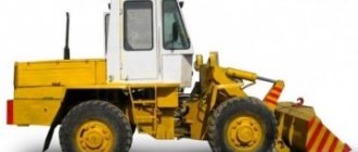
A tractor is a universal vehicle suitable for effective use in a wide variety of situations. The high cross-country ability of tractors, especially in off-road and rough terrain, is one of the most significant factors influencing their popularity and demand for various types of work, as well as delivering goods to the most remote and inaccessible areas. The cross-country ability is ensured by the transmission system, one of the most significant elements of which is the final drive, and it’s time to learn more about it.
Wheel gearbox of the MTZ 82 tractor and its adjustment
» Transmission MTZ 82 » Wheel gearbox of the MTZ 82 tractor and its adjustment
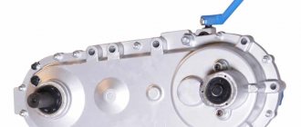
The wheel gearbox of the MTZ 82 tractor is used to increase the torque transmitted to the wheels from the main gear, as well as to rotate the drive and front guide wheels. The gearbox design consists of two pairs of bevel gears - lower and upper. The gear ratio of the lower pair is 4.83 (58:14), the upper one is 1.27 (14:11). The total gear ratio is 6.15.
The upper pair is formed by the gear rims of the vertical shaft and the axle shaft, manufactured as one piece with splined shanks. The axle shaft is connected with the splined end to the differential side gear, and the vertical shaft is connected to the drive gear of the lower pair. The drive gear meshes with the driven gear, which is mounted on a splined portion of the flange that acts as the front wheel hub.
The housings of the upper conical pairs (axle housings) are able to move in the front axle sleeves using screws that engage the rack. This design allows you to continuously adjust the track of the front wheels. From axial movements and rotation in the front axle sleeves, the housings are fixed with wedges.
The axle shaft is located in the housing bore on two tapered roller bearings, the vertical shaft is placed on similar bearings in the pivot tube bore. A spacer ring is mounted between the outer races of the bearings. The vertical shaft and axle shaft bearings are held against axial movement by screws screwed into the pivot tube and housing, respectively.
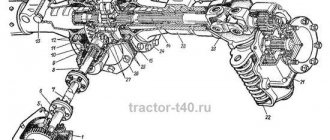
Diagram of the wheel gearbox of the MTZ 82 tractor: 1 - bearing cup; 2 — gearbox cover; 3 - driven gear; 4 — seal glass; 5 - sealing packing; 6 and 34 — shims; 7 — glass of the pivot pipe; 8 - vertical shaft; 9 - cover; 10, 28 and 31 - bearings; 11 — spacer ring; 12 — bearing nut; 13 and 16 — cuffs; 14 — body of the upper conical pair; 15 — axle shaft; 17 — cuff clip; 18 - sealing ring; 19 — pin sleeve; 20 — kingpin pipe; 21 - pin; 22 — bend washer; 23 — suspension spring; 24 — gear housing; 25 - drive gear; 26 — bearing cover; 27 — support washer; 29 - bolt; 30 — adjusting rings; 32 — disk flange; 33 — cuff body.
The oil bath of the upper pair is separated from the lower part of the gearbox using two cuffs.
When the tractor makes turns, the levers attached to the gearbox housings turn their lower part simultaneously with the wheels around the pivot pipe. The pivot pipe is made in the form of a pipe, to the top of which a glass is pressed and welded. The cylindrical area of the glass is inserted into the bore of the body, and the flanged part of the glass is bolted to the body. Using a rubber ring, the glass is sealed in the bore. The pipe pin mates with a sleeve mounted in the gearbox housing. A coiled cylindrical suspension spring is located in the inner part of the pivot tube. The upper end of the spring rests against the collar of the vertical shaft, and the lower end rests against the bearing mounted in the gearbox housing. With different load values, the spring either compresses or expands, and the pivot pipe moves along with the sprung part of the front axle and the vertical shaft relative to the drive gear and sleeve.
The pivot pipe has the ability to move upward until the seal cup collar stops against the sleeve collar; moving downwards until the end of the pivot pipe stops in the gearbox housing.
The drive gear of the lower bevel pair is installed in the housing bore on two ball bearings. The driven gear is mounted on the splined part of the front wheel hub flange. The flange rotates in cylindrical and a pair of tapered bearings. The outer races of the tapered bearings are mounted in a mounting cup located in the gearbox cover.
Maintenance of the wheel gearbox of the MTZ 82 tractor
Gearbox maintenance consists of monitoring the oil level and replacing it in a timely manner; eliminating detected faults, checking and tightening connections. There is no need to adjust the gearing of the lower and upper bevel pairs and the roller bearings of the wheel reducers during operation. Their adjustment is carried out only during repair or replacement of parts.
The oil level in the housing of the upper bevel pair and gearbox should be at the upper edge of the filler holes, which are also control holes. The oil is drained from the gear housing through a hole in the lower cover, and from the upper conical pair using a syringe. To do this, first a syringe is inserted into the filler hole and part of the oil is pumped out, after which the top cover is dismantled and the oil is completely removed through a drill in the vertical shaft.
If a significant decrease in the oil level in the upper conical pair is detected, the causes of the leak should be found out and eliminated immediately. The leakage of lubricant from the upper conical pair along the cuffs of the axle shaft and vertical shaft is not visible from the outside, so the oil can leak out unnoticed, which can cause failure of the assembly unit.
Adjusting the bearings of the upper conical pair
The axial clearance in the bearings of the axle shaft and vertical shaft is adjusted by tightening a special nut. This nut is tightened until the outer races of the bearings rotate tightly, while the races are rotated so that the rollers take the correct position. Next, the nut is unscrewed so that the outer races are able to rotate freely and the axial clearance does not exceed 0.05 mm. Upon completion of the adjustment, the nut is locked by punching.
When tightening the bearings, make sure that the spacer ring does not extend beyond the outer races of the bearings and does not block the subsequent pressing of the bearings.
Adjusting the engagement of the upper conical pair
The lateral clearance in the engagement of the gear rims of the axle shaft and the vertical shaft should be in the range of 0.2-0.55 mm and is adjusted by moving the pivot pipe simultaneously with the vertical shaft using split gaskets mounted between the body and the flanges of the pivot pipe. The position of the axle shaft is not adjustable.
Repair of the front drive axle MTZ-82
We will consider the repair in several stages depending on those symptoms. Which can be observed. Each stage will be illustrated with detailed pictures.
If traces of grease appear on the propeller shaft flange and the main gear housing, this is the first sign that elasticity will be lost and the main gear cuff will collapse. To do this, replace the cuffs and disconnect the driveshaft. First, unscrew the castle nut and remove the cardan flange. Next, unscrew the bolts securing the main gear cup bearings and two mounting bolts. Afterwards, the drive gear is pressed into the glass and the assembly with the cuff itself is removed.
If traces of oil are found on the inner surface of the wheel rim or on the disk flange, this is a sign that the wheel axle is damaged. To do this, you need to remove the wheel and the final drive gearbox as a complete assembly (see the diagram of the arrangement of parts for the final drive gearbox of the MTZ-82 tractor).
then you need to unscrew the two radial bearing securing bolts and remove the driven gear.
So we looked at the main problems of the front axle of the MTZ-82 tractor. We hope that this article was useful to you.
The front axle of the MTZ-82 tractor is manufactured with a drive gearbox. The model has gaskets installed and metal stops. Most experts believe that the device has durable stands. The modification's discs are of the gear type. In order to understand the bridge in detail, you need to consider the device diagram.
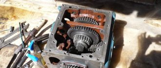
Wheel reducer MTZ-82 and its components
The wheel gearbox of the MTZ-82 tractor (Fig. 41) is used to increase the torque transmitted from the main gear to the wheels and to rotate the front guides and drive wheels.
The wheel gearbox consists of two pairs of bevel gears - upper and lower. The gear ratio of the upper pair is 1.27 (14:11), the lower one is 4.83 (58:14). The total gear ratio is 6.15.
Rice. 41. Wheel reducer of the MTZ-82 tractor
1- bearing cup; 2 — gearbox cover; 3 - driven gear; 4 — seal glass; 5 - sealing packing; 6 and 34 - shims; 7 — glass of the pivot pipe; 8 - vertical shaft; 9 - cover; 10, 28 and 31 - bearings; 11 — spacer ring; 12 — bearing nut; 13 and 16 — cuffs; 14 — body of the upper conical pair; 15 — axle shaft; 17 — cuff clip; 18 - sealing ring; 19 — pin sleeve; 20 — kingpin pipe; 21 - pin; 22 — bend washer; 23 — suspension spring; 24 — gear housing; 25 - drive gear; 26 — bearing cover; 27 — support washer; 29 - bolt; 30 — adjusting rings; 32 — disk flange; 33 — cuff body.
The upper pair is formed by the gear rims of the axle shaft 15 and the vertical shaft 8, made as one piece with splined shanks. The axle shaft is connected with the splined end to the differential side gear, and the vertical shaft is connected to drive gear 25 of the lower pair.
The drive gear 25 meshes with the driven gear 3, which is mounted on the splined part of the flange 32, which serves as the hub of the MTZ-82 front wheel.
The housings of the 14 upper conical pairs (axle housings) can be moved in the front axle sleeves using screws that engage with a rack threaded on the retractable part of the housings.
This allows you to continuously adjust the front wheel track. From rotation and axial movements in the front axle sleeves, the housings 14 are locked with wedges.
The axle shaft is placed in the bore of the housing 14 on two tapered roller bearings 10, the vertical shaft 8 is placed on the same bearings in the bore of the pivot pipe 20. A spacer ring 11 is installed between the outer races of the bearings.
The bearings of the axle shaft and vertical shaft are held against axial movements by screws screwed into the housing 14 and the pivot pipe 20, respectively. The oil bath of the upper pair is separated from the lower part of the MTZ-82 gearbox by two cuffs 18, the axle shaft is sealed by the cuff 13.
When the tractor turns, the levers attached to the gearbox housings 24 rotate their lower part together with the wheels around the pivot pipe 20. The pivot pipe is a pipe, onto the upper part of which a cup 7 is pressed and welded.
The cylindrical part of the glass is pressed into the bore of the body 14, and the flange of the glass is attached to the body with 14 bolts. The glass is sealed in the bore with a rubber ring.
The pivot part of the pipe 20 mates with the sleeve 19, pressed into the gearbox housing. Inside the pivot tube there is a coiled coil spring 23 of the suspension. The lower end of the spring rests on a bearing installed in the gearbox housing, the upper end rests on the collar 17 of the vertical shaft cuff.
When the load changes, the spring is compressed, decompressed and the pivot pipe moves together with the vertical shaft and the sprung part of the MTZ-82 front axle relative to the sleeve 19 and the drive gear 25.
The downward movement is limited by the stop of the end of the pivot pipe in the gearbox housing; upward, the pivot tube can move until the collar of the cup 4 of the seal stops in the collar of the sleeve 19.
The drive gear 25 of the lower bevel pair is mounted on two ball bearings in the housing bore 24. The driven gear 3 is installed on the splined part of the flange - the hub 32 of the front wheel.
The flange 32 rotates in two conical 31 and cylindrical 28 roller bearings. The outer races of the tapered bearings are pressed into the mounting cup 1, installed in the gearbox cover 2, and the outer race of the bearing 28 is pressed into the bore of the gearbox housing 24.
Maintenance of the MTZ-82 wheel gearbox consists of maintaining a certain oil level and periodically changing it, checking and tightening fasteners, and eliminating identified faults.
The gearing of the upper and lower bevel pairs and the roller bevel bearings of the wheel gearboxes do not require adjustment during operation. The need for adjustments arises only during repairs and replacement of parts.
The level of oil poured into the housing of the upper bevel pair and the gearbox housing should be at the edge of the filler holes, which also serve as control holes. Oil is drained from the gearbox housing 24 through a hole in the bottom cover 26.
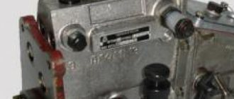
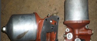
The lubricant is removed from the upper conical pair with a syringe (Fig. 42). First, a syringe is inserted into the filler hole and some of the oil is sucked out. After this, remove the top cover 9 (see Fig. 41), insert a syringe into the drilling of the vertical shaft 8 and completely remove the lubricant.
Rice. 42. Removing oil from the upper bevel pair of the MTZ-82 wheel gearbox
If the inspection reveals a significant decrease in the oil level in the upper conical pair, you need to find out the causes of the leak and eliminate them immediately.
Final drive. Front and rear wheels (MTZ-82R) - MTZ-80:
12-20-3101020 16-34-347010 50Х-2412010-А 50Х-2412020-А 50Х-2412030 50Х-2412040 50Х-2412050 50Х-2412060-Б1 82Р-2401010 82Р-3 101010 82Р-3107010 Rear wheel tire 18.4 R34 Maud. F-44 Front wheel tire 16.0-20 mod. F-76 1 2 3 4 4 5 6 6 7 7 8 8 9 10 11 11 12 12 13 13 14 14 15 16 17 18 19 20 21 22 23 24 25 26 27 28 29 30 30 31 32 33 34 35 36 37 38 39 39 40 41 42 43 44 45 46
List of components from Final drive. Front and rear wheels (MTZ-82R) on MTZ-80
Parts diagrams are for reference purposes only! We do not sell all final drive spare parts. Front and rear wheels (MTZ-82R) for MTZ-80, presented in this list. If there is a “Show prices” link in the right column, these spare parts are from “Final drive. Front and rear wheels (MTZ-82R) are on sale. Availability in warehouses for details and prices, see the product card. If there is no “Show cost” link in the right column, we do not sell such parts and do not accept orders for them.
| № | Part code | Name | Part Information | Show all prices |
Wheel, final drive: device
A tractor is a universal vehicle suitable for effective use in a wide variety of situations. The high cross-country ability of tractors, especially in off-road and rough terrain, is one of the most significant factors influencing their popularity and demand for various types of work, as well as delivering goods to the most remote and inaccessible areas. The cross-country ability is ensured by the transmission system, one of the most significant elements of which is the final drive, and it’s time to learn more about it.
Gearbox and its device
A wheel drive, or as it is also called, a final drive, is a component of the transmission located directly in front of the drive wheels and is responsible for providing a low gear, used in a situation where it is necessary to increase the speed of the drive wheel.
The design of the gearbox in MTZ tractors is made in the image and likeness of a planetary cylinder. It cannot be said that it is distinguished by its complexity and intricacy, but this does not prevent it from performing all the functions assigned to it as efficiently as possible. The unit consists of the following elements:
- Double type hinge;
- Control levers;
- Spur type transmission gear;
- A semi-axial shaft with splines located on it.
The unit body is fastened to the bridge using a special axis fixed to the body with bolts. Bearings and satellites rotate on built-in axes. To avoid unwanted movement of these elements towards the axis, special retaining washers are used. The correct pressing of the unit is checked using an additional fixing screw, and the gear housing itself is adjusted using a tightening nut with a small washer located between it and the bearing.
Tips for use
Oil is filled into the unit up to the lower edge of the filling hole, which is closed with a plug. To drain the oil, use a drain plug that is unscrewed to the desired level. For internal sealing, the cavity of the gearbox is filled with cuffs. Rubber rings are used to seal the bores on the steering knuckle or double-type hinge. The breather installed on the gearbox ensures that optimal pressure is maintained in the cavities of the device. But still, like any other device, the gearbox is not immune from malfunctions and breakdowns. Ignoring the problem is unacceptable, since this can cause the final failure of the gearbox, as well as negatively affect the operation of the entire vehicle as a whole. However, given the fact that dismantling the unit significantly reduces its service life, there is no need to rush into it. After all, even overheating of a unit does not always indicate its malfunction.
Bridge diagram
MTZ-82 front axle (diagram shown below) includes a flange mechanism, as well as a holder. The width of the front pillar is 2.2 meters. The worm device is used with a cover. The pads in the device are used with the cuff. The width of the rack is 2.4 cm. The gears of the model are mounted on spacers. The clamping plates with gearbox are made entirely of brass. A total of two cups are installed on the MTZ-82 (front axle). The device circuit additionally includes a friction block. It includes a breather, as well as a stop.
Wheel reducer maintenance
To increase the reliability of the unit and extend the period of its safe operation, it is necessary to carry out its technical inspection and appropriate maintenance at certain intervals, using special monitoring and measuring equipment. Before starting repair work, you must first disconnect the gearbox from the clutch housing, under which, however, like under the front axle, movable stands are installed. A fixed type stand is placed under the gearbox. Next, you should turn off the hydraulic system and disconnect the tractor frame, roll it out and disconnect the half-frame from the clutch housing.
After disassembly is completed, you can proceed to diagnosing the unit, first of all paying attention to the following points:
- Indicators of oil level in the hydraulic tank;
- Is the engine operating at full power?
- What condition is the chassis in?
- Is there an oil leak?
- Is there pressure in the drain line of the hydraulic motor and at its inlet;
- What is the condition of the fastening joints?
- Are the roller bearings in good condition?
- Does the gear clutch system on the upper and lower bevel pairs need to be replaced?
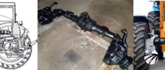
What is the front axle MTZ-82
The front axle diagram includes the following devices:
- Transfer.
- Front differential gearbox.
- Wheel reducer.
The front axle provides agricultural machinery with high ground clearance, as well as the ability to change the track size depending on requirements. This allows the tractor driver to use his machine as an assistant when working at any agricultural point. MTZ-1221 with such devices, equipped with a front axle, can interact with any crops and easily maneuver between rows and beds.
Like other important design elements of Belarus tractors, the front axle requires constant care and maintenance, and replacement of failed parts. If you do not promptly prevent tractor breakdowns and do not carry out scheduled repair work, you will have to do a major overhaul of the MTZ front axle, and this is not cheap. Especially when you consider that a tractor driver can do standard maintenance and troubleshoot minor faults with his own hands: assembling and disassembling the unit and its basic adjustment usually do not cause difficulties.
Maintenance and lubrication of the MTZ 82(80) tractor Belarus
To maintain the tractor in working condition, as well as preserve the life of all units and components of the machine, systematic technical maintenance is required. The manufacturer has developed a regulated system of operations aimed at timely maintenance of all systems and components of the tractor. Thus, a high level of readiness for work and the most efficient level of operation of the machine resource is achieved. In simple words, compliance with the regulations will protect the mechanisms from premature failure, which will generally ensure uninterrupted operation of the tractor at minimal cost.