Malfunctions and repairs of the MTZ tractor generator
What if you find that the ammeter displays discharge current at the rated engine speed?
Check the tension of the generator belt. If the tension is normal, we look for a broken wire in the power supply circuit of the excitation winding. If they are in order, the contacts of the connecting wires have probably become acidic. By the way, when there is an interturn short circuit or a break in the turns in the excitation winding, a short circuit of the stator winding to the housing, or when the reverse or direct polarity diodes of the rectifier break down, the same situation occurs.
Why might there be a high charging current? It is likely that the battery plates will short circuit, and this will lead to a decrease in the internal resistance of the battery and an increase in current.
Noise and knocking in the generator can occur due to loosening of the generator drive pulley, destruction of bearings or wear out of their seats. So the noise is due to the rotor touching the stator.
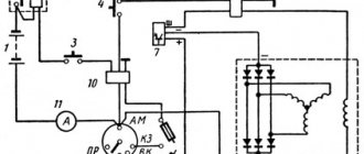
How to check the operation of the 464.3701 generator on a tractor? We connect electricity consumers, bring the engine crankshaft speed to the nominal speed, use a KI-1093 voltammeter to measure between “+” and the unpainted area of the generator housing (Fig. 2.2.1) and, gradually increasing the load current to 30 A, measure the voltage. It must be at least 12.5 V.
Rice. 2.2.1. Scheme for checking the output voltage of the generator under load on the MTZ-80, MTZ-82 tractor: 1 - generator; 2 — voltammeter KI-1003
What to do if the generator voltage is very different from the nominal voltage or there is no voltage at all when the battery is disconnected? The generator needs to be removed for inspection and possibly subsequent replacement. How to check the MTZ-80, MTZ-82 generator? First you need to check the serviceability of the main elements of the generator using a 12 V test lamp.
The sequence of actions is as follows: remove the back plastic cover and the integrated device (ID); Next, we release the leads of the excitation coil and the additional rectifier from the bolts of the terminal panel. We check that there is no short circuit in the diodes or between the windings and the generator housing (see Fig. 2.2.2).
Rice. 2.2.2. Schemes for checking the generator for the absence of a short circuit MTZ-80, MTZ-82 a - how to check the diodes of the rectifier unit; b - how to check the stator windings and reverse polarity diodes; c - how to check diodes of straight polarity; d - how to check the diodes of the additional rectifier; d - how to check the field windings on the generator housing; 1 — generator housing; 2 — terminal “+”; 3 — terminal “Ш”; 4 — outputs of the rectifier block phases; 5 - battery; 6 — terminal “D”; 7 — output terminal of the end of the excitation winding; 8 — output terminal of the beginning of the excitation winding; 9 - control lamp
If there is a short circuit of the diodes, windings or breakdown to the housing, the control lamp lights up. It should be. If the insulation of the windings is damaged or the diodes are faulty, the generator must be replaced. Alignment of the generator is carried out on control and test benches KI-968 or 532M.
First of all, check the voltage of the generator without load. It must be at least 12.5 V at a rotor speed of no more than 1400 rpm. Next, the generator voltage is checked under load, at a load current of 36 A and a rotor speed of 3000 rpm. It must also be at least 12.5 V.
To test the integrated device, the load current is reduced to 5 A, and the rotor speed is tried to be kept within 3000 rpm. In “summer mode” (seasonal adjustment switch in position “L”), the voltage on the generator should be 13.2-14.1 V. In “winter mode” (seasonal adjustment switch in position “W”) the voltage is slightly higher, within 14.3—15.2 V. If these parameters do not correspond, the integrated device must be replaced.
Source
Tractor generators, device repair and maintenance
Like any other type of transport, a tractor is a complex mechanism with its own characteristics of the chassis, ignition and power systems, as well as electrical equipment. The latter includes many components, one of which is the generator and the mechanisms associated with it.
What is a tractor generator and its structure?
A generator is a source of current to maintain the operation of the tractor’s electrical appliances. In order to do its job well, the generator must be simple in configuration and operation, reliable, have a long service life, and small dimensions.
There are two types of generators - alternating current and direct current. Alternating current generators are easy to operate, can be independently regulated and operate without voltage regulators. But alternating current cannot charge the battery without a rectifier.
For tractors with electric start, it is more advisable to use a direct current generator, which gives, accordingly, a constant voltage.
Tractor generator design
In generators, the main components are the stator - a housing with a copper wire winding, and the rotor - a rotating magnet with alternating polarity and fixed to the shaft. It also includes covers (back and front) and bearings in which the rotor rotates. There are 6 cores in the middle of the body. Their set is made of iron plates.
Generator MTZ-80: Connection diagram and fault prevention
Main rules for inspecting the MTZ-80 generator. Generator connection diagram.
In almost any vehicle or work vehicle on wheels, there are two power sources - a battery and a generator. We are not interested in cars, but the MTZ generator is very interesting, and that is what we will consider in detail.
Like absolutely any generator, a tractor generator strictly adheres to the same goals - converting one type of energy into another. Specifically, mechanical to electrical, which successfully performs from the rotation of the crankshaft, as on other equipment.
Generator bearing wear
A car generator has two bearings. One of them is fixed to the rotor shaft, the second is pressed into the central part of the cover. A hum or whistle coming from the generator while the engine is running is a sure sign that one of the bearings has given up its life. A related symptom may be heating of the generator housing. If you notice these signs, hurry to replace the bearings. Otherwise, this will lead to distortion of the rotor shaft or jamming with all the ensuing consequences.
You can check the bearings by removing the alternator belt and turning its shaft by hand. If the rotor rotates easily, without jerking or play, the bearings will still serve. If rotation is difficult or there is play in the shaft, do not delay replacing the bearings.
Preventive inspection of the generator
The main condition for the correct and reliable operation of this device is always a careful inspection, and the MTZ generator is no exception. It is necessary to constantly monitor the quality of the fastening of the wires and the generator itself, the tension of the belt and even the banal cleanliness of the parts.
In other words, it is necessary to clean the case from dirt and dust, if any is found on it. Look behind the instrument panel, where there is an indicator light (light bulb). Before starting the engine, the light should naturally light up. If malfunctions occur, shorting the ground will not do anything, because the indicator light will either not light up at all, or will light up at half power (indication and brightness depend on the specific tractor model).
The MTZ generator is checked for serviceability only when the tractor engine is turned off and cooled down, having first disconnected all wires and terminals from it. The test is carried out with a 12 volt lamp and a battery.
7.3.2. Power supply system (generator). Repair.
For repairs, the generator set is removed from the engine, for which it is necessary (Fig. 139): · turn off the battery disconnect switch; · disconnect the wires from the “+” and “B” terminals of the GU (see Fig. 136); · loosen bolt 1 (see Fig. 139) of the belt tension bar; · loosen nut 11 securing the PG; · loosen bolt 15 securing the pin; · unscrew bolt 1; · holding the control unit so as not to break the mounting brackets, unscrew bolt 17; · remove finger 14; · remove the belts from the pulley; · remove the control unit from the engine. The power unit removed from the engine must be cleaned of dust and disassembled in the following order (see Fig. 136): · disconnect screw 20 securing the wires; · unscrew the two screws securing the brush holder and remove it; · unscrew the two screws securing the IRN and remove the regulator; · unscrew the three screws 4 securing the bearing protective cover; · unscrew the four coupling screws 17 and remove the cover 7 of the generator together with the stator; · unscrew the nuts 1 of the phase leads from the rectifier block and separate the stator 8 from the cover 7; · unscrew the nuts securing the “+” terminal on cover 7 and the three screws securing the rectifier block and remove the block; · unscrew the nut 15 securing the pulley and remove pulley 14; · remove fan 12; · knock out key 13 and remove spacer sleeve 11; · using a puller, remove cover 10 from the rotor shaft along with the bearing; · remove the bearings from covers 7 and 10. After disassembling the parts and unit of the power unit, it is necessary to inspect it, make sure there is no damage, and also check the serviceability of the windings, rectifier unit and voltage regulator. The height of the brushes must be at least 8mm. Worn brushes must be replaced. A chipped pulley must also be replaced. The wear of the pulley grooves is checked with a caliper using two rollers with a diameter of 9 mm inserted into the grooves. The size of the rollers must be at least 83.5 mm. If the size is smaller, the pulley must be replaced. Breakages or cracks in the covers are also unacceptable - such covers must be replaced. The bearings are carefully inspected. If external inspection does not indicate any abnormalities in the bearings, they can be used for further operation. When inspecting cover 7, you should pay attention to the drilling of the hole for the bearing. A groove (ovality) is formed in the upper part of the hole. It is necessary to measure the magnitude of this output. The hole size for the bearing is Ø35±0.008mm. It is allowed to increase the size up to 35.40mm. If the size is larger than permissible, the cover must be replaced. The holes for the bearing in the cover on the drive side are Ø47 +0.027mm. Wear up to Ø47.04mm is allowed. The holes in the cover brackets must be within the size range Ø10.2 +0.24mm. If worn out, new bushings are pressed in and the hole is drilled to the specified value. When inspecting the generator rotor, you should make sure that the bearings are securely fastened to the rotor shaft. The shaft journals are made Ø15±0.07mm for the bearing in the cover on the slip ring side and Ø17±0.06mm for the bearing in the cover on the drive side. The allowed dimensions of the shaft journals are Ø14.94 and 16.9 mm, respectively. If the journals are smaller, the rotor must be replaced. The rotor is checked for a turn short circuit and a short circuit of the excitation winding to the housing. The rotor winding resistance should be 3.7±0.2 Ohm at a temperature of +25°C. A decrease in resistance indicates the presence of a turn short circuit, and the rotor must be replaced. There may be desoldering of wires from slip rings.
In this case, the wires must be soldered to the rings and the soldering area must be painted over. If the rotor rings have wear, they must be ground and then polished. The diameter of the rings must be at least 30.0 mm; if the size is less than 30 mm, the rings must be replaced. The generator stator is checked for winding short circuit to the housing. The check is carried out in the same way as checking the rotor with a test lamp. The stator winding may have a turn short circuit. This leads to overheating of the stator coils and their failure. The defect is determined by external inspection by a change in the color of the coils and a violation of their reliable, play-free fit in the stator grooves. A stator with damaged coils must be replaced. The serviceability of the rectifier unit is checked with a test lamp with a voltage not exceeding 24V, as shown in Fig. 140. The block is checked in the forward and reverse directions. To check in the forward direction, the “+” of the constant voltage source is connected through a test lamp to the “-” rectifier block, and the “-” source is connected to the “+” block (“+” of the block is determined by the shaped hole 6). In this case, the control lamp should be on (see Fig. 140, a). If the polarity is reversed (see Fig. 140, b), the lamp should not light. If these conditions are not met, the unit is faulty and must be replaced. The integrated voltage regulator is checked using a test lamp connected to a 24-26V constant voltage source (Fig. 141). To check, connect the “+” of the power supply to the “B” terminal of the regulator, and “-” to the base. The control lamp turns on at the “+” of the power source and terminal “Ш” of the regulator. If the regulator is working properly, the control lamp lights up at full voltage evenly. If the lamp does not light or does not burn at full intensity, or flashes, the IRN is faulty and must be replaced.
Signs of stator winding malfunction
To begin with, it would be nice to know what connections are used for this device. This is a simple matter: the negative wire of the battery is attached to the “M” terminal of the generator, and the positive wire is connected to the “W” terminal through a test lamp.
- As mentioned above, if the winding is faulty, the indicator light on the dashboard will not light up, or will light up very weakly. In addition, the current strength will not exceed 3-3.5 amperes.
- If the light does not light up at all (regardless of the modification of the tractor engine), then the winding is simply torn, rotted, or oxidized (it must be emphasized).
- We change the connection. We connect the minus terminal of the battery to any terminal of the generator, and the plus terminal again through the indicator light to terminal B of the generator.
With this connection, the lamp will not light up, but... If it manages to turn on, it means:
- one diode or several at once has shorted;
- the insulation between the heat pipe and the rectifier is broken;
- The positive wire on the generator housing is shorted.
Recommendations
As they say, if you’re not sure, don’t overtake. If you cannot guarantee your knowledge of electrical engineering, then you should not undertake an inspection (much less a repair).
Checking proper operation
To be confident in the unit you are using, it is advisable to check its functionality before each use. For this purpose, a special control lamp is used. When the tractor ignition is activated, it should light up, and when the engine starts successfully, it should go out immediately.
The lamp can only turn off after increasing the crankshaft speed. If this does not happen, we are talking about the presence of malfunctions in the operation of the generator. To do this, turn off the engine and then follow the following instructions:
- Check the tension level of the alternator belt and adjust it if necessary.
- Connect the negative wire from the battery to terminal “M” and the other to terminal “B”.
- Turning on the lamp at this stage indicates a malfunction of the rectifier.
- Next, the “-” from the battery will need to be connected to the AC terminal, and the “+” to the “B” terminal. If the lamp lights up, the rectifier diode is broken down.
You can also combine the “+” from the battery with the AC terminal, and the “-” with the “M” of the generator. When the lamp is turned on, the problem most likely lies in a short circuit in the stator winding or a broken diode.
Care should be taken when working with electrical components, as they can quickly become unusable if not handled correctly.
How to disassemble and check the MTZ-82 generator: connection diagram
The generator on the MTZ-82 is designed to recharge the battery and maintain the functionality of lighting equipment and lighting devices. The unit is installed on the cylinder block and has a belt drive from the power plant shaft. If the equipment fails, the battery is discharged, which makes it impossible to start the engine (if an electric starter is used).
Malfunctions
GU breakdowns can occur in both electrical and mechanical parts. Signs of defects are the absence of charging current when the car engine is running or a voltage drop when a large load is turned on. In the first case, the malfunction is most often associated with a lack of excitation current or failure of the voltage regulator, and in the second, with slipping of the drive belt.
All defects can be eliminated, except those associated with damage to the stator and rotor windings. In this case, a unit replacement of the mechanism is necessary.
Repair
To eliminate malfunctions, the power unit must be dismantled from its original location. The fault can only be identified by disassembling the device. The result should be 2 halves: the first, consisting of the front cover with a pulley and armature, the second - from the rear cover and stator. To carry out checks and measurements, the stator winding is disconnected from the rectifier unit. The coils are checked for integrity and breakdown to the housing.
To measure the resistance of the windings, a tester is used, and a 100 V megohmmeter is used to measure short circuits to the housing.
The use of 220 V indicator lamps is prohibited due to safety requirements. The field winding is checked in the same way. Damaged elements must be replaced.
When checking the rectifier, all diodes ring in the forward and reverse directions. Defective parts are soldered out and replaced with good ones. A mandatory check is to test the performance of the voltage regulator, which is often called a “chocolate bar”. For this purpose, a 24 V test lamp is used. These actions check the integrity of the excitation current supply circuit to the rotor winding.
Service
Generator maintenance should be regular. Due to the fact that its dismantling is associated with additional related work, during normal operation it is limited to periodic external inspection. At the same time, make sure that no water gets on the body of the PG, and that the connecting wires do not touch the rotating parts. Conductors with damaged insulation must be replaced or insulated. Maintenance of bearing units, wear control and replacement of brushes are combined with repairs during complete disassembly of the power unit.
Models of generators for MTZ-82
The electrical system included several modifications of generators:
- Until the end of the second quarter of 1975, the production equipment used a G304-D1 modification unit equipped with a PP362-B relay regulator. The generator is distinguished by the location of the switching terminals on the rear of the housing.
- From the second half of 1975 (according to some sources - from the beginning of 1976), the G306 model unit began to be used, working in tandem with the PP362-B voltage regulator.
- In the 80s The G309 modification unit began to be used, characterized by increased power and increased service life of parts. Some machines used the 700-watt G464 generator, which was supplanted by the G964 product (and its modifications), which had a power of 1000 W.
- Since the beginning of the 2000s. a unit model AT 1150.04.1 was introduced (or an analogue with serial number 9695.3701-1), which has an 11% increase in output and an improved voltage corrector. On tractors with air conditioning and a D-245 diesel engine, unit 9702.3701 is used, capable of generating current up to 100 A (power is 1400 W).
How to check the diode bridge of a generator without removing it from the car
The diode bridge acts as a kind of rectifier, converting the alternating current generated by the generator into direct current. It usually consists of six semiconductor diodes, three of them are “positive”, the other three are “negative”, i.e. the first pass current in one direction, the second in the other. The rectifier can be checked either with the generator removed or without dismantling it. Let's consider both options.
Before checking the diode bridge of the generator without removing it, it is necessary to disconnect all wires from it and from the voltage regulator, having first disconnected the ground terminal from the battery. First, let's check the rectifier for a short circuit. Turn on the multimeter in ohmmeter mode, connect the positive (red) probe to terminal “30” of the generator (positive contact of the bridge), and the negative one to the generator housing. With a working rectifier, the device readings will tend to infinity. If the resistance is several ohms, the rectifier is faulty.
Design and operating principle
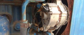
The unit is mounted on the side of the engine crankcase on a rotating base; the upper fixation point allows you to adjust the tension of the drive belt. Torque is transmitted from a pulley mounted on the toe of the crankshaft using a segment key. The belt also rotates the pump of the liquid cooling system; if the drive breaks or the generator rotor is jammed, further operation of the tractor is impossible. The end covers of the housing have shaped channels for supplying air and draining water entering the internal cavities of the product.
An electrical machine consists of a stator, inside of which there is a fixed package of sheets stamped from electrical steel, on which there are copper windings. The coils form phases, within which the elements are closed in series, the phases themselves are combined according to a triangle diagram. A rotor shaft is mounted inside the stator on ball bearings, and a package of steel plates is pressed onto the axis. The supports are secured in removable covers. A stamped impeller is provided at the toe of the shaft to ensure cooling of the equipment.
Ball bearings are equipped with rubber protective caps that prevent water from washing away the lubricant. The design of the equipment includes excitation coils located at the ends of the stator. At the moment of operation, voltage from the battery is supplied to the windings, allowing the generator to be brought into operating mode.
The rectifier unit mounted inside the installation casing is equipped with a metal casing that provides cooling of the semiconductor diodes during operation.
If there is no battery on the tractor (the diesel engine is started using a PD-10 gasoline starter), then it is necessary to transfer the generator from the independent excitation mode to the parallel excitation state. To do this, you need to briefly (for 1 second) connect a 12 V DC source to the excitation windings. The positive cable is applied to terminal Ш, and the negative cable to terminal M. The procedure ensures the magnetization of structural parts, which allows you to put the generator into operating mode without external influence .
After the engine starts, the rotor begins to rotate, inducing a magnetic field in the stator protrusions, which varies from minimum to maximum depending on the position of the moving rotor. The created ripples make it possible to induce an alternating 3-phase current in the stator windings, which is then rectified by the semiconductor unit. The voltage level is adjusted by a separate relay, which has a season switch (in winter, the generated voltage is higher, which ensures recharging of the battery with cooled electrolyte).
Generator device g 306
The generator consists of two main components: a rotating rotor and a stationary stator.
The stator consists of sheets made of electrical steel. The three-phase winding coils are installed on nine protrusions on its inner side. Three coils connected in series with each other form a delta-connected phase. The ends of the phases are brought out to the three contact bolts of the panel and connected to the rectifier.
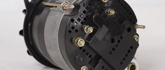
Generator g 306: 1 - pulley; 2 — fan impeller; 3 - rectifier heat sink; 4 — rectifier housing; 5 — front cover; 6 and 11 - ball bearings; 7 — excitation coil; 8 - stator; 9 - rotor; 10 - stator phase winding; 12 — back cover; 13 - panel.
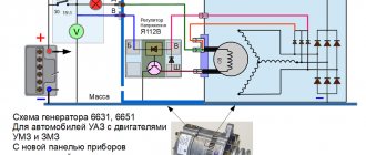
Electrical circuit of the MTZ 82 generator
Generator connection diagram
The connection diagram of the generator to the tractor's on-board network does not depend on the equipment model.
The design provides 3 or 4 outputs:
- point B or + is used to switch the positive wire from the battery;
- block M is connected to the negative pole of the battery;
- connector D (used on new versions) passes through the charging indicator device and the ignition switch to the positive output of the battery;
- plug Ш is brought out to the tractor body (negative pole);
- point W is found on part of the generators and is connected to the tachometer.
Generator rotor
The generator rotor consists of sheets of electrical steel in the shape of a six-pointed star and is mounted on a shaft that rotates in two ball bearings - the rear and front covers. At the outer end of the shaft, a pulley cast from cast iron is installed and secured with a nut, to which the fan impeller is attached.
On the front cover there is a pair of welded claws (one for attaching the generator, and the second for adjusting the belt tension), and on the back cover there is one claw for fastening. To drain water and condensate that has entered the inside of the generator, there are special holes on the cylindrical part of the covers.
An excitation coil is installed on the inner end part of the front cover. The beginning of the excitation coil winding is connected to the housing, and the end, using a flexible wire, is brought to terminal III. The cover and stator are locked from rotation relative to each other and are tightened with three tightening screws.
The generator rectifier consists of a heat sink and housing made of aluminum alloy, and six silicon diodes. Three diodes of direct polarity are mounted in a heat sink isolated from the housing, and three diodes of reverse polarity are installed in the housing. The ends of the diodes of reverse and direct polarity are connected in pairs into phases and are brought out to the “-” terminals along with the stator phases. The negative pole of the rectifier is routed through the mounting bolts to the generator housing, and the positive pole is routed to terminal B along with the heat sinks.
Generator characteristics
The main technical parameters of the generators are given in the table.
| Parameter | G304-D1 | G309 | AT 1150.04.1 |
| Power, W | 250 | 1000 | 1150 |
| Operating voltage, V | 12 | 14 | 14 |
| Permissible load, A | 29 | 70 | 82 |
| Rotation speed at rated power, rpm | 3600 | 4500 | 3000 |
How to check the generator
A car generator is the main source of energy in the on-board network, and if it malfunctions or fails, you won’t be able to drive for long on one battery. This is why it is so important to monitor the performance of the generator.
The full range of generator checks includes:
In most cases, checking a car's generator with your own hands is not difficult, since no matter what car you check on, the principle is the same. But still, many car owners often wonder: how to check the generator with a multimeter or with improvised means?
Next, we’ll look in more detail at how to check a generator in a garage without special stands that are used at service stations.
Maintenance of devices at MTZ
During operation, oil particles and dust accumulate on the generator, which should be removed with a clean rag. If dirt has accumulated in the internal cavities of the equipment, the unit must be removed for disassembly and cleaning with a rag moistened with gasoline. The formation of a layer of oxides on the terminals or destruction of the insulation of the wires of the tractor on-board network is not allowed.
When starting the engine, the control lamp should go out (on some tractors the indicator is allowed to blink in idle mode; when the frequency increases to 1400 rpm, the lamp turns off).
Do not operate equipment with a damaged pulley or fan impeller. It is recommended to periodically check and adjust the belt tension (deflection arrow 30 mm with a load of 3 kg). An over-tensioned drive will overload the rotor bearings. Due to wear of the elements, the normal clearance between the rotating unit and the stator is disrupted. Cracks or tears in the belt cause the drive to slip.
Frequent problems and their diagnosis
1 So, the control light does not go out, what should you do? Do not panic and immediately check the belt tension. If it is in order, then you need to check the contacts for oxides. If performance is not restored after cleaning, you need to check the output voltage. It should not be lower than 12.5 volts.
2 If you hear extraneous noise and knocking during operation, the problem is the loosening of the pulley fixing nut. However, bearing failure is also possible. Diagnosed by routine disassembly. The bearing will noticeably crunch when worn and will need to be replaced. The nut can be lubricated with thread sealant and tightened more tightly.
The main thing is that the fit on the pulley is not disturbed. You can notice a broken seat by the free movement of the nut. In this case, it needs to be replaced.
3 Under no circumstances should the bearing be knocked out. The shaft can be damaged, and this is a major repair. A special puller is required.
Otherwise, other generator breakdowns rarely occur on MTZ tractors.
Source