Fuel injection pump malfunctions on a diesel engine lead to loss of power, increased fuel consumption, difficult starting, increased exhaust smoke, and others. Typical breakdowns of a high-pressure fuel pump in a diesel car include water getting into the plunger pairs, a drop in pressure in the plunger pair, damage to the integrity of the sealing rings, sensor or wiring malfunctions (in electronically controlled diesel engines). Ideally, the injection pump should be checked at a special stand in a car service center, but simple checks of the fuel pump can be done in a garage.
Design and principle of operation
The fuel injection pump device includes such mechanisms as:
- pump compartment housing;
- high pressure fuel pump bearing cover housing;
- inflation hose;
- plunger pair and plunger pusher;
- spring elements;
- mode selection regulator and coarse and fine filters;
- fitting for the fuel drain and injection system;
- fuel injection regulator;
- pressure reducing valve;
- an electromagnetic valve, which is necessary to shut off the fuel supply;
- rack, nozzle and coupling half.
The operating principle of the injection pump is as follows:
- Movement is set from the crankshaft mechanism using a mechanical transmission.
- The rotation of the cam shaft begins. This rotation provokes displacement of the pusher elements.
- The pushers begin to compress special springs.
- The springs cause the plunger to start working and lift it.
- The plunger closes the intake valve and displaces fuel fluid.
- The fuel begins to be sprayed using nozzles.
- The plunger lowers and opens the intake mechanism.
Where is the check valve located?
The check valve allows fuel to flow in only one direction - from the fuel tank to the engine. When the engine is turned off, it blocks unused fuel from draining back into the fuel tank. Do not confuse a check valve with a pressure reducing valve, which regulates the fuel pressure when supplied to the injectors; in the event of a malfunction of the valve, the fuel would be supplied without pressure, which makes it impossible for it to move further into the engine.
The check valve is located on the fuel rail between the fuel tank and the injectors. This arrangement allows, in addition to the main functions, to regulate the pressure at the injection pump inlet. On KamAZ models intended for operation in Arctic conditions, the OK is located in front of the heating system.
Shaft with cams
The shaft with cams transmits displacement to the plungers of the pump sections, diesel fuel is supplied to the chambers at the right time. The shaft is made of steel, the loaded surfaces are calcined with cement powder to 0.7-1.2 mm, rotation occurs through two bearings. The shaft is protected from leaks by a cuff, the material of the product is rubber. The front end of the shaft drives a clutch that sets the diesel injection angle. Rotating, the shaft transmits pressure to the pushers and then to the pump plungers through the heels. By changing the thickness of the heels, we influence the nature of the fuel supply; an increase in thickness provokes an early supply and vice versa.
Fuel system check valve: how to check the valve
Fuel system safety valve
It goes without saying that vehicle fuel systems are quite complex devices, which it is better not to approach without specific knowledge. On the other hand, knowledge of hardware and some experience is already considered as an opportunity to independently repair this or that defect. For example, if a fuel system check valve requires attention.
Design
ATTENTION! A completely simple way to reduce fuel consumption has been found! Don't believe me? An auto mechanic with 15 years of experience also didn’t believe it until he tried it. And now he saves 35,000 rubles a year on gasoline! Read more"
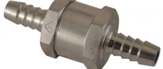
Any check valve (OC) is nothing more than an element that ensures the movement of fuel in one direction. It can block the flow of unused fuel back into the fuel tank.
Its design, as a rule, implies the presence of a calibrated saddle made of soft metal. The valve allows gasoline or diesel fuel to pass in one direction, but when the engine stops, the valve automatically closes and the movement of liquid stops.
Fuel system valve and pipe
Despite the simplicity of the design of the bypass valve, its malfunction or its banal absence in the system can lead to great difficulties. For example, the normal functioning of the motor is impossible, and starting it becomes more difficult.
There is no need to confuse the OK with a pressure reducing valve. The latter is responsible for pressure stability, although it operates in conjunction with a check valve.
Read more about pressure reducing valve. It is responsible for equalizing the pressure in the section of the fuel rail where the fuel liquid enters the injectors. If it were not for this valve, the injectors would receive fuel under different pressures or without it, as a result of which they would not be able to transfer gasoline further into the chamber.
Pressure reducing valve or pressure regulator
The regulator stops supplying fuel to the injectors when the engine stops and the ignition is turned off. The shut-off mechanism simply operates, cutting off part of the fuel line. Gasoline remains only in the area between the fuel pump and the ramp, if OK. If not, there will be no fuel in the system; it will leak back into the tank.
Location
The OK can be installed in different places: in the fuel pump housing, on the ramp, or simply between the tank and the injectors. The exact location depends on the specific car model.
For example, on most diesel cars the OK is placed between the low-pressure pumping device and the injection pump. Here, in addition to its main functions, it is responsible for the stability of the pressure at the injection pump inlet. Examples: KAMAZ, Tatra, Man trucks, etc.
Where is the fuel system check valve located?
But in KamAZ vehicles intended for operation in arctic conditions, in Magirus truck systems, a check valve is installed in front of the heating system.
On VAZs with injectors equipped with 16-valve engines, the OK is installed either in the fuel pump or on the ramp. But in carburetor VAZs of the old type, on the “classics”, it is not there. But the function is provided. The role of OK is played by the fuel pump itself, installed on the BC.
Caring owners of old cars, including the Mazda 323 and Opel Cadet, modernize the fuel systems themselves by installing check valves closer to the carburetor or injector. This makes it easier to start the engine, because fuel is no longer drained back into the tank, even at the lowest temperatures or depressurization of any connections.
Problems
Why does OK fail? This happens quite often, since the market today has become more defective as a percentage. Chinese counterfeits at low and medium prices attract the attention of motorists who do not suspect a trick. It is worth installing such a part, and after a while problems arise.
How to check the fuel system check valve
If the part is of high quality, then the malfunction occurs for a natural reason - due to wear. As a rule, either the spring or the membrane deteriorates. It is extremely rare for the valve to fail completely, which is a credit to it.
Another common cause of failure that we have seen lately is low quality fuel. Gasoline or diesel fuel mixed with water is harmful to many parts of the fuel system.
Typical symptoms of an OK malfunction look like this:
- the speed changes unexpectedly in idle mode;
- the engine starts only after pressing the gas pedal, although previously it started only by twisting the starter;
- at low speeds the engine operates extremely unstable;
- Liquid leaks from the supply and return fuel pipes, although the sealing of the hoses is beyond doubt.
OK has a mechanical design. On the one hand, it seems to be good and can be easily fixed if you understand the mechanics. In fact, the element is non-separable, and it is impossible to diagnose its functionality using electronic devices, sensors, for example.
Ways to check functionality OK
Various methods are used to determine the serviceability of the valve. One of them is based on checking the pressure level. It is measured by a pressure gauge connected to that part of the system that supplies the engine with gasoline. The normal pressure level should be 3 kg/cm2 (passenger cars). Also, the level should not drop sharply when the engine is stopped. Otherwise, this also indicates a malfunction of the return valve.
Pressure gauge
Some experts advise checking OK by squeezing the return hose. In this case, if everything is in order with the valve, the pressure level should increase. The method is suitable for those machines in which the “return” is made of a rubber hose. However, many cars are equipped with metal pipes or the “return” is too short, it is impossible to compress it.
There is another diagnostic method, without a pressure gauge, suitable for engines that are unstable and have difficulty picking up speed. Again, the return line is pinched. At the same time, you need to monitor the operation of the internal combustion engine. If the engine speed increases and all cylinders are functioning normally, the OK is most likely faulty.
Obviously, nothing good can be expected from a damaged valve. A drop in engine speed, unstable cylinder operation, difficult starting, airing - all this will come sooner or later if the valve does not work.
Clamp the return line
It will be interesting to consider the reason for the airing of the system, which opens our eyes to the principle of operation of the OK. After stopping the engine, a certain amount of fuel liquid must remain in the chamber, awaiting the next start. If there is no valve or it is damaged, gasoline/diesel goes back into the tank, and air takes its place. Until the system is ventilated and the pressure is brought back to normal, the engine will not start.
Installing additional OK
It is recommended as an option for upgrading a system in which the original valve no longer holds (or does not exist at all). You just need to try to choose a high-quality valve, and the cross-sectional dimensions must be suitable. For example, some models of VAZ valves are not suitable for foreign cars. You can install them, but they don't last long. As soon as you accelerate sharply or climb a mountain, the valve slips and the car begins to choke.
It would be better to buy OK from parsing. Find the fuel pump of a specific car model, check the valve, if it works, take it. It does not matter whether the pump itself is running or not. The main thing is to hold the valve.
Fuel system check valve Nexia
All that remains is to embed the valve into the line, in any convenient place. For example, between the fuel pump and the filter. Then check on a hill or when accelerating to see if the car is choking.
Bosch KamAZ Euro-3 injection pump: design and adjustment
The German fuel injection pump for KamAZ Euro-3 is a common component of new models. However, Bosch pumps break down more often. The fact is that operating conditions for trucks in Russia are very different from German ones, so many owners replace Bosch fuel injection pumps with YAZDA (Yaroslavl plant). The latter are inferior in the accuracy of measuring portions of incoming fuel, but are better suited for use on local roads.
The design of the Bosch KamAZ Euro-3 fuel injection pump is not fundamentally different from Euro-2 or domestic fuel injection pumps.
For proper operation, regular diagnostics of the injection pump and adjustment are necessary, which is necessary in the following cases:
- Increased fuel consumption
- No fuel supply to the injector
- Noises in the pump
Operating rules
In order for the mechanism to work as long as possible, the most basic principles of operation should be observed. Namely.
- Use quality fuel.
- Clean and replace all system filters regularly.
- Do not use unknown mixtures to increase power or the like.
- Regularly clean and flush all components of the fuel system.
- In case of breakdown, preventive maintenance and to set up the correct operation of the KamAZ injection pump, visit specialized service centers with experienced specialists.
- Eliminate fuel system leaks.
- Maintain tightness.
- Regularly check the strength of the pump to the engine. If necessary, tighten it.
Bosch KamAZ Euro-2 injection pump: design and adjustment
Bosch Euro-2 injection pump consists of:
- Frame
- Injection advance clutch
- All-mode regulator
- Plungers
- Booster pump
- Shaft
- Springs
- Valves
Bosch injection pump control can be mechanical or electronic; Euro-2 is often equipped with electronic control.
Most often, breakdowns occur during long-term operation; plungers and pumps wear out. Due to these breakdowns, fuel is supplied in larger quantities or not supplied at all.
In order to prevent damage to the fuel injection pump, it is necessary to remove sediment from the coarse filter daily and change the fine filters several times a year. If the injection pump breaks down, it is better to contact a specialist.
Purpose of the parking brake system of the KAMAZ 5320 vehicle
The parking brake system is designed to hold the car stationary in a parking lot; it can serve as a backup brake system, braking the car if the service brake system fails.
The parking brake system brakes the vehicle using the brake mechanisms of the rear axle (rear bogie), which are driven by spring energy accumulators located above the brake chambers of the service brake system. Moreover, energy accumulators have reverse action - when air is supplied to its working cavity, the brake mechanism is released, and when air is released, it is inhibited due to the energy of the compressed spring. This provides increased safety when operating the vehicle.
This is interesting: List of frequent breakdowns of KamAZ fuel injection pumps and ways to eliminate them - let's look at them in order
Malfunctions and repairs
You can repair KamAZ fuel injection pump yourself if you have the necessary tools and equipment.
Main fuel injection pump malfunctions and reasons for their occurrence:
- Water in the fuel mechanism. This breakdown may indicate a malfunction of the fuel filter element, diluted fuel, or a leak in the fuel drives.
- Reduced and uneven supply of working fluid. In this case, it is recommended to check the plunger for damage, and also inspect the discharge valves and rack clamps. The capacity of the injectors should be checked.
- The diesel fuel is running out. The cause of this breakdown may be a leak in the fuel drive. The damaged element should be replaced.
- The drive is tearing. It is recommended to inspect the crankshaft, as well as the main components of the power unit for damage and foreign bodies.
- Delay of the working fluid injection system. Such a malfunction can be caused by damage to the plane of the adjusting bolt of the pusher element, the roller axis and failures in the rotation speed of the cam shaft.
How to remove and disassemble
Removal from engine:
- Remove the terminal from the battery.
- Remove the radiator.
- Remove the vacuum pump.
- Remove the oil dipstick guide pipe.
- Remove the oil filter filter mechanism.
- Turn the crankshaft in the direction of rotation until it stops.
- Disconnect fuel drives.
- Remove the vacuum hose.
- Block the crankshaft from turning.
- Unscrew the bolt in the center of the coupling.
- Remove the chain tensioner.
- Pull out the pump by dismantling the fuel pedal drive.
Disassembling the KamAZ fuel injection pump is done as follows:
- It is necessary to remove the metering type valve from the end of the pump housing. To do this, you need to unscrew the bolts of the pressure plate and release the advance valves of the injection system.
- Then you should remove the fastenings on the top cover.
- You need to disassemble the control board to gain access to the electronics.
- It is necessary to set the required position of the crankshaft.
- Then you need to dismantle the bearing using special equipment.
- At the end, all parts should be washed and their surface polished.
Adjusting the pneumatic corrector
The function of the KamAZ 740 injection pump pneumatic corrector is to regulate the fuel supply. When the air flow pressure decreases, the amount of fuel supplied is reduced, which prevents overheating and smoking of the engine. Also, the operation of such equipment affects engine oil consumption: if everything is in order, then oil consumption is uniform.
Adjusting the pneumatic corrector allows you to change the amount of fuel entering the injectors. The whole process is very simple, does not have a complex sequence of actions and can be easily done with your own hands. The pneumatic corrector is adjusted by two bolts:
The first is responsible for spring tension and is located coaxially with the spool. The corrector operates at increased pressure, which means it is necessary to increase the spring tension by tightening the bolt.
The second screw is responsible for the direct supply of fuel; unwinding it will increase the volume of incoming fuel.
On the Internet you can find pictures and videos showing step-by-step adjustment of the corrector. Fuel supply corrector circuit:
How to add or reduce fuel
Adjusting the Bosch injection pump on KamAZ makes it possible to add fuel, i.e. set the required fuel supply value.
Procedure for reducing fuel:
- Using a key of 13, you need to adjust the air flow to the mechanisms of the power unit. Thanks to this, diesel will be able to mix with air.
- Make adjustments to the corrector and start the motor for testing.
- If necessary, you need to further tighten the air flow until the smoke stops coming out.
In order to add fuel to the KamAZ injection pump (Euro-2 or Euro-3), you need to do the following:
- Tighten the special screws that are located in the upper and side parts of the working fluid supply.
- When unscrewing the bolts, you need to increase the gap for the passage of the combustible mixture. This will help normalize the performance of the power unit and the lubrication system of the high-pressure fuel pump.
- Having increased the diameter of the hole, you should start the engine and check the operation of all systems.
How to install correctly
Installation (installation) of the fuel pump must be carried out using special equipment.
In order to correctly supply and install a high-pressure fuel pump on a KamAZ truck, do the following:
- The vehicle is installed on a special platform.
- Mount the driven clutch onto the advance clutch and secure everything with bolts.
- Turn the coupling so that the bosses of the driven type coupling half are in a horizontal position, and the mark on the end part is in the pointer area.
- Install the flange assembly with the drive coupling half and plate packs. The flange should be located on the left side of the housing.
- Install the fuel pump along with the coupling onto the engine and secure everything with mounting bolts.
- Before tightening the bolts, adjust the flatness of the plate packs by moving the flange along the drive shaft.
- The pump is mounted on a block of cylindrical elements in a vertical position, preventing it from blocking.
- The injection pump sections are connected to the injectors.
- Adjust the advance angle of the injection system.
- Check the presence of oil fluid in the injection pump housing.
- Connect the oil inlet and outlet pipes.
Install the ignition on KamAZ
We will answer the question posed using the KamAZ 740 as an example. To do this, we will describe the ignition procedure of the KamAZ 740, which is similar to many models of this class.
Installation of the KamAZ 740 ignition is carried out in several stages:
- getting started we'll start by raising the truck cab
- we will fix the cabin on supports to protect the person’s work
- find the flywheel on which you will find the rod, it is located on the back of the flywheel on the top left side.
- lift the rod and rotate it ninety degrees, then return it to its original place
- find two bolts on the flywheel housing, unscrew them, you will need a seventeen mm wrench.
- To continue working, remove the mudguard
- through the slotted passage of the casing into the flywheel we insert a hard alloy rod 400 mm long and 10 mm in diameter
- perform rotational movements with the crankshaft until movement is blocked
- if the injection pump coupling is located with the scale up, you need to ensure that two marks coincide: zero with the mark on the fuel pump flange, secure with two bolts
- if the part is positioned in the opposite direction, lift the stopper and rotate the crankshaft one 360 degrees. After this, repeat the steps described above.
Price and reviews
Injection pump purchase and rental price:
- purchase - from 17,500 rubles;
- This vehicle part cannot be rented.
Vladimir, 39 years old, Magnitogorsk: “I’ve been working at KamAZ-53215 for the second year now. Recently I started having problems with the high pressure fuel pump. A Euro-3 version was installed, and the fuel injection pump had to be replaced.”
Vitaly, 41 years old, Vladivostok: After 4 years of operation of the KamAZ, fuel fluid began to leak. The cause of the breakdown was a broken seal of the fuel drive and pump.
The repair was done quickly, because... all spare parts are easy to find.
Mikhail, 53 years old, Krasnodar: “The truck has an injection pump installed according to Euro-4 standards. The problems started after 2 years of operation. All failures were associated with uneven supply of working fluid. I entrusted the repair to the specialists at the service center.”
Oleg, 35 years old, Tver: “Recently, this part had to be replaced on KamAZ-54115. Buying a new part cost 20,000 rubles. I installed it myself, following all the recommendations in the instructions.”
Leonid, 48 years old, Yekaterinburg: “Water appeared in the fuel pump. I had to disassemble the injection pump. The cause of the malfunction was the filter element, which was replaced. Now everything works properly."
List of common KamAZ fuel injection pump breakdowns and ways to fix them. Check valve KAMAZ fuel injection pump
The fuel supply system ensures fuel purification and its uniform distribution throughout the engine cylinders in dosed portions and at strictly defined times.
The engines use a split-type fuel supply system, consisting of a type 337 fuel injection pump with a speed controller, a fuel priming pump, injectors, coarse and fine filters, a pre-start pump, high and low pressure fuel pipes, a solenoid valve and EFU flare spark plugs.
The fuel supply system diagram is shown in Figure 1.
A fuel coarse filter and a fuel pre-priming pump must be installed in the fuel supply system of the facility where the engine is used.
Fuel from the tank is supplied through the coarse filter and the pre-start pump 18 by the fuel priming pump into the fine filter 16.
From the racing filter through the low-pressure fuel pipe 14, the fuel enters the injection pump 21, which, in accordance with the operating order of the cylinders, distributes the fuel through the high-pressure pipes 1-8 to the injectors 10. The injectors inject fuel into the combustion chambers.
Excess fuel, and along with it the air that has entered the system, is discharged into the fuel tank through the injection pump bypass valve 24 through tube 12 and the fine filter nozzle valve 23.
The nozzle (see Fig. 2) is a closed type, with a five-nozzle sprayer and hydraulic control for lifting the needle mod. 273-31 for engine mod. 740.11-240. Maud. 273-21 with sprayer JSC "YAZDA" or mod. 273-51 with sprayer for engines mod. 740.13-260 and 740.14-300.
All parts of the nozzle are assembled in body 6. A spacer 3 and nozzle body 1, inside of which there is a needle 12, are attached to the lower end of the nozzle body with a nut 2.
The body and the atomizer needle form a precision pair. The sprayer has five spray holes.
Spacer 3 and body 1 are fixed relative to body 6 by pins 4.
Spring 11 rests at one end against rod 5, which transmits force to the spray needle, and at the other end against a set of adjusting washers 9, 10.
Fuel is supplied to the injector under high pressure through fitting 8 with a slot filter 13 built into it, then through the channels of housing 6, spacer 3 and sprayer body 1 into the cavity between the sprayer body and needle 12 and, lifting it, is injected into the cylinder.
The fuel that has leaked through the gap between the needle and the nozzle body is discharged through the channels in the nozzle body and drained into the tank through drainage pipes 9 and 11 (see Fig. Engine fuel supply system).
The injector is installed in the cylinder head and secured with brackets. The end of the nozzle nut is sealed against gas breakthrough with a corrugated copper gasket. O-ring 7 protects the cavity between the nozzle and the cylinder head from dust and water.
Due to the possibility of engine failure, the installation of sprayers of other models other than those specified in the manual is strictly prohibited.
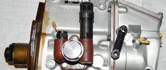
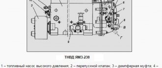
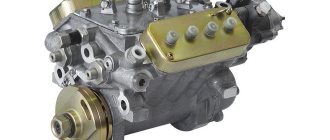
The high pressure fuel pump (see Fig. High pressure fuel pump) is designed to supply strictly dosed portions of fuel under high pressure into the engine cylinders at certain points in time
The 740.11-240 engine is equipped with a fuel injection pump mod. 337-40 with a plunger diameter of 11 mm and a plunger stroke of 13 mm, a reinforced fuel injection pump housing with a tunnel for a cam shaft of increased diameter and reinforced bearings, a high-capacity injection valve with a diameter of 7 mm.
The fuel injection pump is equipped with an automatic fuel injection advance clutch (AMOVT) with a nominal rotation angle of the driven coupling half relative to the driving half - 1 °.
The 740.14-300 engine is equipped with a fuel injection pump mod. 337-80.01 with a plunger diameter of 10 mm and a plunger stroke of 13 mm.
The fuel injection pump is equipped with AMOVT with a nominal rotation angle of the driven coupling half relative to the driving half - 4°30.
The 740.13-260 engine is equipped with a fuel injection pump mod. 337-42 with a plunger diameter of 11 mm and a plunger stroke of 13 mm. Injection pump without AMOVT.
Eight sections are installed in the injection pump housing 1, which consists of a housing 6, a plunger sleeve 8, a plunger 7, a rotary sleeve 4, a discharge valve 10, pressed to the plunger sleeve by a fitting 11 through a sealing gasket 12.
The plunger performs a reciprocating movement under the action of the cam of the shaft 35 and spring 3.
The pusher is secured from turning in the body with a block 49.
The cam shaft rotates in roller bearings 34 installed in the covers and attached to the pump housing. The axial clearance of the cam shaft is adjusted by shims 33. The clearance should be no more than 0.1 mm.
To increase the fuel supply, plunger 7 is rotated by bushing 4, connected through the axis of the driver to rack 5 of the pump.
The rack moves in guide bushings 30. Its protruding end is closed with a plug 31.
On the opposite side of the pump there is a bolt 48, adjusting the fuel supply by all sections of the pump, the bolt is closed with a plug and sealed.
Fuel is supplied to the pump through a special fitting to which a low-pressure tube 14 is bolted. Then, through channels in the housing, the fuel flows to the inlet holes of the 8 plunger bushings.
At the front end of the housing, at the point where the fuel exits the pump, a bypass valve 29 is installed, which provides pressure in the low pressure line at operating conditions of 0.13-0.19 MPa (1.3-1.9 kgf/cm2).
The valve opening pressure is regulated by selecting adjusting washers 50 inside the valve plug.
The pump is lubricated by circulation, pulsating, under pressure from the general engine lubrication system.
The speed regulator is all-mode, direct-acting, changes the amount of fuel supplied to the cylinders, depending on the load, maintaining a given crankshaft speed.
The regulator is installed in the camber of the injection pump housing (see Fig. injection pump).
On the cam shaft of the pump there is a drive gear 36 of the regulator, the rotation of which is transmitted through rubber nuts 16.
The driven gear is made as one piece with a weight holder 19, rotating on two ball bearings.
When the holder rotates, the weights 22, swinging on the axes 20, diverge under the action of centrifugal forces and move the coupling 23 through the thrust bearing 21.
The clutch, resting against pin 24, in turn, moves the load clutch lever 45. One end of the lever is fixed to the axis 46, and the other is connected through a pin to the fuel pump rack.
Lever 11 (Fig. Scheme of operation of the speed controller) for controlling the governor is rigidly connected to lever 7. Spring 8 is attached to lever 7. To levers 9 and 6 – starting spring 10.
During operation of the regulator, the centrifugal forces of the loads are balanced by the force of the spring 8. As the crankshaft rotation speed increases, the weights, overcoming the resistance of the spring 8, move the lever 2 of the weight clutch with the injection pump rack - the fuel supply decreases.
When the crankshaft rotation speed decreases, the centrifugal force of the loads decreases, and lever 2 with the injection pump rack moves in the opposite direction under the action of the spring force - the fuel supply and the crankshaft rotation speed increase.
The fuel supply is stopped by turning lever 3 (Fig. Injection pump regulator cover) to stop the engine until it stops at bolt 6. In this case, lever 3, overcoming the force of spring 8 (Fig. Diagram of the operation of the speed regulator), turns the levers through pin 47 (Fig. Injection pump) 2 and 5, the rack will move until the fuel supply is completely stopped.
When the force is removed from the engine stop lever, it will return to its operating position under the action of spring 25 (Fig. Injection pump).
Automatic fuel injection advance clutch mod. 333 for engine 740.11-240 and mod. 333-60 for engine 740.14-300 (See figure) changes the start of fuel supply depending on the engine speed.
The clutch sets the start of fuel supply that is optimal for the work process throughout the entire range of speed modes. This ensures an acceptable level of emissions of harmful substances from exhaust gases, acceptable efficiency and severity of the process at various engine speed conditions.
On engines mod. 740.11-240 and 740.14-300 use an injection advance clutch of increased energy intensity with a 25 mm landing cone.
The driven coupling half 13 is fixed on the conical surface of the front end of the injection pump cam shaft with a key and a nut with a washer, the driving coupling half 1 is mounted on the driven hub (can be rotated on it).
A sleeve 3 is installed between the hub and the coupling half.
The weights 11 swing on axles 16 pressed into the driven coupling half in a plane perpendicular to the axis of rotation of the coupling.
Spacer 12 of the drive half of the coupling rests with one end against the load pin, and with the other against the profile protrusion.
Spring 8 strives to hold the load in the position of abutment in sleeve 3 of the drive half-coupling.
When the rotation speed of the engine crankshaft (fuel injection pump camshaft) increases, the loads diverge under the influence of centrifugal forces, as a result of which the driven coupling half rotates relative to the drive half in the direction of rotation of the cam shaft, which causes an increase in the advance angle of fuel injection.
When the rotation speed of the crankshaft (fuel pump camshaft) decreases, the loads converge under the action of springs, the driven coupling half rotates together with the pump shaft in the direction opposite to the direction of rotation of the shaft, which causes a decrease in the advance angle of fuel injection.
ATTENTION! Checking and adjusting the injection pump, as well as replacing plunger pairs and sealing gaskets of injection pump sections must be carried out in a specialized workshop and by a qualified specialist.
It is STRICTLY PROHIBITED to install fuel injection pump models that do not correspond to the given engine model, due to deterioration in the quality of the engine operating process, increased emissions of harmful substances from exhaust gases, exhaust smoke and to avoid premature engine failure
Injection pump drive of reinforced design.
The drive is equipped with 5 rear and front plates, each 0.5 mm thick, made of 65 G steel.
All bolts in the injection pump drive must be of strength class R100 and tightened with a torque of 6.5-7.5 kgf.m. The tightness of all bolts must be checked with a torque wrench. Before installing the bolts, check for the presence of centering sleeves.
ATTENTION! Spring washers are installed only under the nuts securing the plates to the driven coupling half.
Deformation (bending) of the front and rear plates is not allowed. The coupling bolt of the drive coupling half of the injection pump drive is tightened last.
The fine fuel filter (see Fig. Furnace filter) finally cleans the fuel before entering the injection pump.
It is installed at the highest point of the fuel supply system to collect and remove air into the tank along with part of the fuel, through a valve - a jet installed in the filter housing.
At a pressure in the fuel supply cavity of 25-45 kPa (0.25-0.45 kgf/cm2), the valve shifts, and at a pressure of 200-240 kPa (2-2.4 kgf/cm2), the valve opens completely, allowing fuel to pass into the tank .
ATTENTION! When replacing filter elements, you must strictly follow the rules for servicing the fuel supply system. Contaminants must not enter the engine fuel supply system.
It is necessary to use filter elements of only approved models in the fine fuel filter, namely: 740.1117040-01, 740.1117040-02, 740.1117040-04.
Fuel pump 13 (Fig. Injection pump) is a piston type, designed to supply fuel from the tank through coarse and fine filters to the inlet cavity of the injection pump.
The pump is installed on the rear cover of the regulator and is driven by the eccentric of the injection pump cam shaft.
The pump body contains: a piston, a piston spring, a rod sleeve and a pusher rod, inlet and discharge valves with springs.
The eccentric of the cam shaft of the injection pump through the roller, pusher 15 and rod imparts reciprocating movement to the piston of the low-pressure fuel pump.
High performance fuel priming pump without hand pump.
The pump operation diagram is shown in the figure below.
When the pusher is lowered, the piston 10 moves downward under the action of the spring 4. A vacuum is created in cavity “A” and inlet valve 3, compressing spring 2, allows fuel into the cavity. At the same time, the fuel located in the injection cavity “B” is forced into the line, bypassing the injection valve 8, connected by channels to both cavities. In the free position, the discharge valve closes the channel of the suction cavity.
When piston 10 moves upward, the fuel filling cavity “A” enters cavity “B” under the piston through injection valve 8, and the inlet valve closes.
When the pressure in the discharge line increases, the piston does not make a full stroke following the pusher, but remains in a position that is determined by the balance of the fuel pressure force on one side and the spring force on the other.
The piston-type fuel pre-priming pump is used to fill the fuel system with fuel before starting the engine and remove air from it.
The pump is installed in the fuel system of the product. The pump consists of a housing, a piston, a cylinder, a handle and rod assembly, a support plate and a seal.
The fuel system should be pumped with a fuel pre-bleeding pump.
When moving upward, a vacuum is created in the space under the piston. Inlet valve 11 (see figure), compressing spring 2, opens and fuel enters the pump cavity.
When the handle moves down, the discharge valve 13 opens, and fuel under pressure enters the discharge line, ensuring the removal of air from the engine fuel system through the FTOT nozzle valve and the injection pump bypass valve.
After bleeding the system, you must lower the handle and lock it by turning it clockwise. In this case, the piston will press against the rubber gasket, sealing the suction cavity of the low pressure fuel pump.
ATTENTION! It is not allowed to start the engine with the handle unlocked due to the possibility of air leaking through the piston seal.
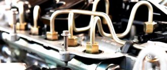
Fuel pipes are divided into low pressure fuel pipes - 0.4-2 MPa (4-20 kgf/cm2) and high pressure pipes of more than 20 MPa (200 kgf/cm2),
Low pressure fuel lines are made of steel pipe with a cross-section of 10×1 mm with soldered tips.
High-pressure fuel pipes of equal length (1 = 615 mm), are made of steel pipes with an internal diameter of 2+0.05 mm by landing at the ends of connecting cones with crimp washers and union nuts for connection with the injection pump fittings and injectors.
To avoid damage from vibration, the fuel pipes are additionally secured with brackets to the intake manifolds.