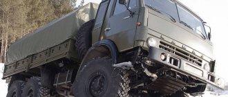
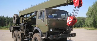
The KamAZ-4310 is distinguished by increased cross-country ability on the roadway. This vehicle is positioned as a reliable machine that can handle the loads well. Freight vehicles began to be produced in the USSR in the early 1980s. It was mainly produced for the needs of the Soviet Army.
The vehicle dimensions are as follows: 7650×3590×2500 mm. Moreover, the weight exceeds 8 tons. Acceleration to 60 km/h occurs in approximately 35 seconds. However, about 30 liters of fuel are consumed per 100 km.
Technical features of KamAZ-4310
KamAZ 4310
The machine has several modifications that differ in power, the presence/absence of a winch, and a berth. The peculiarity of the basic version is that it includes a platform with a voluminous awning and a rear, folding side. More than 25 people can fit in the back of this vehicle. The cabin provides comfort and convenience to the driver when moving.
The vehicle dimensions are as follows: 7650×3590×2500 mm. Moreover, the weight exceeds 8 tons. Acceleration to 60 km/h occurs in approximately 35 seconds. However, about 30 liters of fuel are consumed per 100 km.
Characteristics of the power take-off
Appearance of the COM
A power take-off (PTO) is a working mechanism that in most cases is installed on vehicles suitable for cargo transportation. This unit allows you to save on fuel consumption.
The power take-off box on KamAZ-4310 is fixed at the rear end of the box with several bolts. It includes spare parts that cope well with high loads. There are diaphragm pneumatic chambers.
The power take-off has an activation mechanism, which has a housing, a cover, and a rod. Thanks to the presence of an electro-pneumatic valve, air is supplied towards the pneumatic chamber.
It is worth considering the device, purpose of the RK, as well as the principle of operation.
Signs of a transfer case breakdown on a KAMAZ 4310, 43118 vehicle
If there are obvious signs of breakdown, then the RC must be replaced; this should be done in the following cases:
First of all, this is a characteristic knocking noise that occurs due to damage to the teeth on wheels equipped with such teeth, and if the bearing ceases to function due to wear.
Due to the fact that the teeth on the couplings, on the gears and on the gearboxes become unusable, the gears are switched off randomly. The shift fork foot may also be damaged.
If the parts that are in the gearbox are worn out, this leads to the fact that the gears are difficult to engage, the gear shift rods jam, and the differential locks. The power take-off on KAMAZ-4310, 43118 vehicles may also jam.
Possible damage to the RC, for example, chips, cracks. Failure of fastenings and other damage that can be considered mechanical.
How to make repairs
- Using the provided hole with a plug, drain the oil from the valve;
- Remove the special shields located on the floor of the platform, having first unscrewed the clamp nut;
- Separate the driveshaft, which is considered the main one, and the drive shaft;
- Disconnect the drive shaft on the front axle from the drive;
- Disconnect the drive shaft on the intermediate axle;
- Disconnect the driveshaft located on the drive from the power take-off;
- Also disconnect the speedometer, that is, the converter plug on the Kamaz-4310, 43118;
- There are also wires for indicator lamps, which are responsible for the differential lock and overdrive. Also downward.
- On the Republic of Kazakhstan, remove the ground wire from the bracket
- The hoses connecting the pneumatic chambers are the same as above: differential, power take-off and both gears, high and low.
- Unscrew the nuts on the control valve and remove the bolts to dismantle the control valve.
Transfer case device
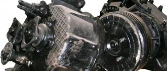
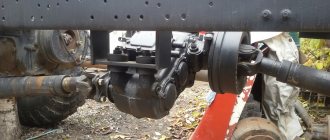
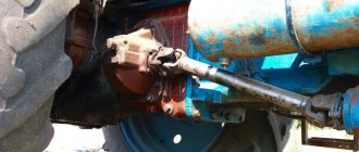
It should be noted that there is a transfer case (TC) on the KamAZ-4310. Its constituent parts are shafts, a crankcase, and a gear responsible for overdrive. Also, the gearbox is supplemented with a center differential.
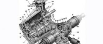
Transfer case diagram
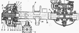
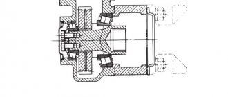
The KamAZ-4310 transfer case diagram clearly shows that the input shaft is mounted on roller bearings. They tolerate combined loads well. The input shaft bearing (front) has a cone shape. This element is located at the front end of the crankcase cover. Gears are designed for long service life.
Thanks to the bearings, the movement of the intermediate shaft is carried out. Gears and satellites are reliable. The RK includes a membrane pneumatic chamber, which activates the center differential lock. This ensures the rotation of all wheels. When driving over rough terrain, the differential is locked.
Thus, a transfer gearbox is typical for vehicles with increased cross-country ability. It ensures the transmission and division of the moment of force. This device includes mechanisms that affect the quality of the trip. Also, it helps out if you are driving on rough terrain. Transfer cases differ in the number of gears.
Disassembling the transfer case KamAZ 4310.
List of tools
Tools and accessories: keys 10X12, 12X13, 17X19" socket wrenches 10, 17, 36, 46 mm, special wrench for round slotted nuts 90-95, hex keys 8, 12 mm, torque wrench KRM-60, transfer case bearing pullers included in the kit I801-02, replaceable head 17 mm, special pliers I801.22.000-01, I801.23.000-01, grip for units, press, vice, mandrel, knob, stand, copper hammer, bronze drift, center punch, pliers, screwdriver, hammer, set of probes, hair brush, utensils for paste, lubricant, kerosene, technological bolt M10X X 1.25-30 (2 pcs.), torque handle, 131M, bench, stop, pin driver.
Transfer case KAMAZ 4310
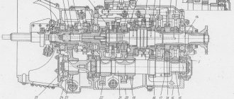
Transfer case: 1 input shaft flange: 2 - input shaft; 3, 4, 8, 13. 16, 17, 29, 40 - bearings; 5 - drive gear; 6 — top hatch cover; 7 — power take-off gear; 9- power take-off clutch; 10 — power take-off; 11 - oil sump; 12 — low gear gear; 14 — bearing cover; 15 — satellite; 18 – rear axle drive shaft; 19 — rear differential race; 20 — main gear; 21 — differential low gear gear; 22 – sun gear; 23 — front cage; 24– transfer case housing; 25 – top gear gear: 26 – transfer case housing cover; 27 - magnetic plug; 28, 30. 41 - couplings; 31 — drive gear of the electric speedometer converter drive: 32 — front axle drive shaft; 33 - fork; 34 — spring: 35 — rod; 36 — membrane: 37 switch; 38 — lock bolt; 39 — intermediate shaft; 42 — constant mesh gear
A power take-off gear 7 is welded to the drive gear 5 of the input shaft. The low gear gear 12 and the high gear gear 25 are mounted on rollers. The differential is of a planetary type with four satellites 15, a sun gear 22 and a main gear 20, the main gear 20 is connected to the rear axle drive shaft 18. The rotational torque of the sun gear is transmitted to the front axle drive shaft 32. When the differential is running (unlocked), constant and uniform traction on all axles is ensured, and additional loads in the transmission are eliminated. Depending on road conditions, the differential can be turned off (locked), and then the drive shafts of the front and rear axles rotate as one unit.
Step-by-step description of the process of disassembling the KAMAZ transfer case
1. Unscrew nut 28, unscrew it and remove it together with washer 29. Remove flange 30 of the rear axle drive. Hammer, socket wrench 46 mm, stop, screwdriver
2. Unscrew and remove bolts 74 with spring washers. Remove the bearing cover 32, oil washer 34 and sealing gasket 33. Wrench 17 mm
3. Unscrew and remove bolts 73 with spring washers. Remove the adjusting ring 35 and use a puller (Fig. 3) to remove the bearing 36 (see Fig. 2). Remove the rear bearing cover 37 with sealing gasket 38. 17 mm wrench, screwdriver, special pliers, puller
Fig.3 Removing the rear axle drive gear bearing
4. Unscrew two plugs 76 from the housing 66 of the control rod locking mechanism and remove them with gaskets 77. Socket wrench 36 mm
5. Unscrew and remove bolts 75 securing the locking mechanism housing with washers. Remove the housing 66 with the sealing gasket 65, unscrew the conical plugs 78, remove the locking device from the housing: two balls 79 and a pin 80. Hex key 8 mm, socket key 17 mm
6. Remove bolts 47 securing the transfer case housing cover with washers. Remove cover 46 with shafts and gasket 45. 19 mm wrench, screwdriver.
9. Rotate the crankcase 90°. Unscrew bolts 25 with washers. Press in power take-off box 24, remove gasket 23. Mandrel, hammer, 17 mm wrench, screwdriver
10. Unscrew and remove bolts 72 with washers, remove cover 71 of the side hatch of the crankcase with gasket 70. Socket wrench 13 mm, screwdriver
11. Remove cotter pin 67, unscrew locking bolt 68 of the power take-off fork. Unscrew bolts 27 with washers, remove mechanism 26 for switching on power take-off box 24 with gasket. Remove plug 69
From the rod of the mechanism 26 for turning on the power take-off and clutch 22
From the power take-off shaft. Wrench 17 mm, screwdriver, pliers
12. Unscrew bolts 40 with washers, remove cover 41 of the rear bearing of the intermediate shaft with gasket 42. Press rings 43 and 39 of the outer rear bearings of the intermediate shaft and the rear axle drive shaft out of the crankcase. Screwdriver, wrench 17 mm, hammer, mandrel, bit
13. Rotate the crankcase 90°.
14. Unscrew safety valve 21 from the top cover.
15. Unscrew nuts 20, remove washers 19, top hatch cover 17 with gasket 16. Unscrew studs 18. 19 mm wrench, screwdriver
16. Remove the cotter pins 62, unscrew the locking screws 63 of the gear shift forks.
Pliers, socket wrench 10 mm
17. Unscrew bolts 52, 65 with washers, remove shift mechanisms 53 and 64 with adjusting 55, 82 and sealing gaskets 54, 83. Remove the gearshift forks 64 from the rods. Wrench 17 mm, screwdriver, hammer, mandrel
18. Unscrew bolts 51 with washers, remove front axle drive housing 50 with gasket 49. 17 mm wrench, screwdriver, puller.
19. Unscrew and unscrew nut I securing the input shaft flange, remove washer 2 and flange 3. Socket wrench 46 mm, hammer
20. Unscrew bolts 5 with washers and remove cover 6 of the front bearing of the input shaft with gasket 7. 17 mm wrench, screwdriver
21. Remove the support washer 8 and compress the ball bearing 9. Mandrel, hammer, screwdriver
22. Press cup II of the front bearings out of the cover, remove gasket 12 and press in outer ring 10 of the roller bearing. Bronze drift, hammer, screwdriver
23. Unscrew bolts 57 with washers and remove cover 58 of the front intermediate shaft bearing with gasket 59. 17 mm wrench, screwdriver
24. Remove thrust rings 60 and 48 from the grooves of the intermediate shaft and differential bearings. Screwdriver, special pliers
25. Press shafts 13, 61 and differential 81 out of the transfer case housing cover. Hammer, mandrel
26. Remove thrust ring 6 from the shaft. Special pliers.
27. Use a puller (Fig. 4) to remove the inner ring 5 (see Fig. 5) of the rear bearing assembly. Puller, special pliers.
Fig.4 Removing the inner ring of the roller bearing of the rear axle drive low gear
Fig. 5 Transfer case primary shaft: 1 – front bearing inner ring; 2 – gear; 3 – primary shaft of the transfer case; 4 – segment key; 5 – inner ring of the roller bearing; 6 – thrust ring.
28. Press gear 2 from the shaft and remove key 4. Hammer, screwdriver, press
29. Place the intermediate shaft on the workbench, unscrew and unscrew nuts I, 13 (Fig. 6), remove washers 2, 12. Hammer, chisel, socket wrench 46 mm
Rice. 6. Transfer case intermediate shaft 1.13 – nuts; 2,10,12 – washers; 3.7 – bearings; 4- gear; 5- carriage; 6- transfer case intermediate shaft; 8 - first gear of the intermediate shaft; 9- spacer sleeve; II - inner ring of the bearing.
30. Using a puller (Fig. 7), remove bearing 3 from shaft 6 (see Fig. 6), and the inner ring of bearing II (Fig. 6.) Mandrel, hammer, pullers
Fig.7 Removing the inner ring of the rear bearing of the intermediate shaft
31. Remove washers 10 and gear 8 of the first gear of the intermediate shaft with bearings 7 and spacer sleeve 9. Mandrel, hammer
32. Remove gear 4 of constant engagement with carriage 5 from the shaft. Mandrel, hammer
33. Remove the inclusion carriage 5 from gear 4.
34. Install the differential on the workbench. Clamp in a vice, open and unscrew nut I (Fig. 8). Vice, hammer, chisel, special wrench 90-95 mm
Fig8. Transfer case differential: 1 – nut; 2- ball bearing; 3 – splined bushing; 4 – carriage; 5 – roller bearings; 6- overdrive gear; 7 – support washer; 8.15 – bolts; 9- front cage; 10,13,18 - bushings; 11 – front axle drive gear; 12- satellites; 14- rear differential race; 16 – pin; 17 – rear axle drive gear; 19 – reduction gear; 20 – inner ring; 21 – thrust ring.
35. Use a puller (Fig. 9) to remove from the front race 9 (see Fig. ball bearing 2. Puller
Fig.9. Removing the differential race bearing
36. Remove carriage 4 and slotted bushing 3.
37. Remove overdrive gear 6 with roller bearings 5, support washer 7, bushing 10. Hammer, mandrel, screwdriver
38. Remove bolts 8. Wrench 17 mm
39. Remove the thrust ring 21, use a puller (Fig. 4) to remove the inner ring 20 (Fig. roller bearing. Puller, special pliers
40. Press out gear 19 of the reduction gear with bushing 18 using two technological bolts screwed into the holes of the front cage. Technological bolts, hammer, mandrel, wrench 17 mm
41. Remove gear 17 of the rear axle drive.
42. Remove bolts 15. Remove rear cage 14 of differential. Wrench 17 mm, hammer, mandrel
43. Remove four satellites 12 with bushings 13 and gear II of the front axle drive. Mandrel, hammer
44. Install the power take-off in a vice. Unscrew and unscrew nut 12 (Fig. 10), remove washer II. Socket wrench 46 im, hammer, chisel, vice
Fig. 10 Power take-off 1 – shaft; 2 – glass; 3 – ball bearing; 4 – spacer sleeve; 5.11 - washers; 6 – gasket; 7- cover; 8 – screw; 9 – cuff; 10 – flange; 12 – nut
45. Remove flange 10 of the box with cuff 9. Mandrel, hammer
46. Remove screws 8, remove bearing cup cover 7 with gasket 6. Screwdriver
47. Press shaft I out of cup 2 with bearings assembly. Mandrel, press
48. Using a puller (Fig. 11), remove two ball bearings 3 and spacer sleeve 4 from shaft I (Fig. 10). Puller
49. Install the front axle drive housing assembly with the drive shaft on a workbench and clamp it in a vice. Bench workbench, vice
50. Unscrew and unscrew nut 29 (Fig. 12), remove washer 28. Hammer, chisel, 46 mm socket wrench
Rice. 11 Removing the power take-off drive shaft bearings
Rice. 12 Front axle drive housing assembled with shaft: 1.12 – bolts; 2 – cover of the differential lock control mechanism assembly; 3 – diaphragm; 4 – fork rod; 5 – return spring; 6 – crankcase; 7 – plug ball; 8,16, 23 – gaskets; 9 – hatch cover; 10.25 – bolts with washers; 11 – cotter pin; 13 – differential lock fork; 14 – speedometer drive worm; 15 – fitting; 17 – speedometer drive gear; 18 – locking clutch; 19 – shaft; 20 – ball bearing; 21 – thrust ring; 22 – oil-separating washer; 24 – bearing cover; 26 - cuff; 27 – flange; 28 – washer; 29 – nut
51. Remove flange 27 from shaft 19 of the front axle drive. Mandrel, hammer
52. Remove bolts 25 with washers. Remove the bearing cover 24, oil washer 22 and sealing gasket 23. Wrench 17 mm, screwdriver
53. Unscrew bolts 10 with washers, remove hatch cover 9 with gasket 8. Wrench 12 mm
54. Remove cotter pin II, unscrew the bolt securing the fork 13 to the differential lock. Socket wrench 10 mm, pliers
55. Remove bolts I, remove cover 2 of differential locking mechanism 3 with diaphragm. Socket wrench 10 mm
56. Remove rod 4 with spring 5 from housing 6 and locking fork 13. Hammer, bronze drift
57. Remove the differential lock fork 13 from the locking clutch groove. Remove coupling 18.
58. Remove the thrust ring 21 from the groove of the bearing 20. Press the shaft 19 out of the bearing and the speedometer drive worm 14. Screwdriver, hammer, mandrel, special pliers
59. Use a puller (Fig. 13) to press out fitting 15 and gear 17 of the speedometer drive from the housing 6 (Fig. 12) of bearing 20. Remove the crankcase from the vice. Mandrel, hammer, puller
Rice. 13 Removing the front axle drive shaft bearing
60. Remove bolts I (Fig. 14) from the gear shift mechanism. Wrench 10 mm
Rice. 14 Downshift mechanism: 1 – bolt; 2 – cover; 3 – diaphragm; 4 – glass of return springs; 5, 10 – springs; 6 – crankcase; 7 – thrust ring; 8 – rod; 9 – washer; 11 – nut; 12 – rod
61. Remove cover 2, diaphragm 3. Unscrew cup 4 of return springs
62. Remove the spring 5. Pliers
62. Shine thrust ring 7. Remove rod 8 from rod 12 together with springs 10 and washers 9, unscrew nuts II. When the strokes of the rods are adjusted, the adjusting nuts II do not need to be unscrewed. Screwdriver, pliers, 12 mm wrench, special pliers
63. Remove rods 12 from crankcase 6.
64. Disassemble the mechanism for engaging the overdrive gear. See Operations 60-63.
65. Wash the parts in flushing liquid and check their technical condition.
Transfer case problems
The RK on KamAZ helps vehicles overcome road obstacles and improves ride quality. Proper care of the transmission system on the driver's side can extend its life.
Each of the constituent parts of the Republic of Kazakhstan needs timely verification. Repairing differentials is considered expensive from a financial point of view. The main sign that a breakdown of this element has occurred is the appearance of a howling sound when moving at high speed. Motor vehicles are subject to mandatory diagnostics.
What is the cause of vibration? As a rule, this manifestation is a consequence of the fact that the fastening bolts have become loose. Also, it is worth inspecting the drive levers to see if the differential is worn out.
If it is difficult to switch on the speeds, you should check the condition of the rods. If the gear shift drive is deformed, the speeds will operate spontaneously.
If any of the above manifestations occur, disassembly of the transfer case is required. Worn clutch teeth and gears must be replaced. The troubleshooting procedure should be entrusted to specialists working in a specialized service center.
Causes of breakdowns with transfer case
The main reason that there was a problem with the functioning of the KamAZ-4310 transfer case is frequent travel on the roadway at high speeds, which places increased loads on the KamAZ vehicle system. The consequence of this is wear of the seals. When repairing a box, you need to use high-quality components that are covered by a warranty.
Among the signs that the KamAZ-4310 has a breakdown with the transfer case, the following manifestations should be highlighted:
- the appearance of a characteristic knock;
- gear shifting occurs with difficulty;
- the driving dynamics have worsened.
As a rule, knocking noise from the gearbox occurs as a result of damage to the teeth on the wheels when the bearing wears out. You should also check the shift fork. The appearance of extraneous noise from the KamAZ gearbox may be due to the fact that the transfer case has chips or cracks.
_______________________________________________________________________________
Repair and maintenance of Kamaz vehicle transfer case
The transfer case (transfer case) assembled with the power take-off of Kamaz-4310, 55111, 43118 vehicles must be replaced in case of the following malfunctions: - Increased noise and knocking during operation as a result of wear of bearings, shafts and gears, as well as breakage of gear teeth. — Arbitrary disengagement of gears as a result of wear of the teeth of the clutches of the gear wheels and shift carriages, and the shift fork legs. — Difficulty shifting gears as a result of wear of the transfer case parts, sticking of the gear shift rods, engagement of the differential lock and engagement of the power take-off (PTO) KamAZ-4310, 55111, 43118. — Mechanical damage that disrupts its normal operation (holes, cracks in the support area fastenings, breaking the threads under the cover bolts, etc.) Removing the transfer case KamAZ-4310, 55111, 43118 - Drain the oil from the transfer case by unscrewing the drain plug - Unscrew the clamp nut and remove the platform floor shields above the transfer case - Disconnect the main driveshaft from the transfer case boxes - Disconnect the driveshaft of the front axle drive from the transfer case - Disconnect the driveshaft of the intermediate axle drive from the transfer case - Disconnect the driveshaft of the winch drive from the power take-off KamAZ-4310, 55111, 43118 - Disconnect the plug connection of the speedometer converter - Disconnect the wires from the control switches lamps: differential lock activation; engaging upshift and downshift gears - Disconnect the ground wire from the bracket on the transfer case KamAZ-4310, 55111, 43118 - Disconnect the hoses of the pneumatic chambers: differential lock engagement; shifting up and down gears; turning on the power take-off - Load the transfer case, unscrew the self-locking nuts of the four transfer case mounting bolts, remove the bolts and lower the transfer case onto the cart. Installing the transfer case KamAZ-4310, 55111, 43118 - Roll the cart with the transfer case under the car, mount the transfer case, lift it, install the cushions, align the holes in the box supports with the holes in the beam and the transfer case suspension bracket, insert four bolts and tighten the self-locking nuts. — Remove the lifting device from the transfer case and roll out the cart — Connect the hoses of the pneumatic chambers: engaging the differential lock; shifting up and down gears; turning on the power take-off - Connect the ground wire to the transfer case KamAZ-4310, 55111, 43118 - Connect the wires of the indicator lamp switches: turning on the differential lock; engaging upshifts and downshifts. Install the wires under the bracket on the transfer case - Connect the plug connection of the speedometer converter - Attach the driveshaft of the winch drive to the power take-off box Kamaz-4310, 55111, 43118 - Attach the driveshaft of the intermediate axle drive to the transfer case. The tightening torque of the propeller shaft bolt nuts is 59–69 N m (6–7 kg/cm) — Attach the main propeller shaft to the transfer case. Tightening torque of the driveshaft mounting bolt nuts 118–137 Nm (12–14 kg/cm) — Attach the front axle drive driveshaft to the transfer case. The tightening torque of the nuts of the propeller shaft mounting bolts is 78-88 Nm (8-9 kgf) - Fill the transfer case housing with oil to the level of the lower inspection plug. Replacing the cuff of the driven shaft of the Kamaz-4310, 55111, 43118 gearbox. Removing the cuff of the driven shaft of the gearbox - Remove the driveshaft of the intermediate bridge - Engage one of the gears of the Kamaz-4310, 55111, 43118 gearbox - Open and unscrew the nut securing the flange on the driven shaft of the box gears, remove the washer - Use a puller to remove the flange from the driven shaft - Remove the bolts securing the rear bearing cover of the driven shaft to the gearbox housing. Carefully, so as not to damage the sealing gasket, separate the cover assembly with the cuff from the box housing - Remove the cuff from the cover Installing the driven shaft cuff Kamaz-4310, 55111, 43118 - Wipe the seating surface under the cuff in the cover and coat it with lubricant - Press the cuff into the cover — Coat both sides of the gasket with sealing paste, install the gasket on the bearing cover and secure the cover to the box housing with bolts and spring washers. — Coat the inner surface of the flange under the seal with grease. Install the flange on the driven shaft of the box, install the washer, tighten the nut with a torque of 196-235 Nm (20-24 kg/cm) and tighten the nuts - Install the main driveshaft - Turn off the gear in the Kamaz-4310, 55111, 43118 gearbox Replacing the transfer case cuffs (transfer case) KamAZ-4310, 55111, 43118 The cuffs must be replaced if they are worn or damaged, causing oil leakage.
Fig.1. Transfer case (transfer case) KamAZ-4310, 55111, 43118 1, 20, 28 - nuts; 2, 8, 29 — washers; 3 — drive shaft flange assembly; 4, 31—cuff assembly; 5, 25, 27, 40, 47, 51, 52, 57, 72, 73, 74, 75, 85 — bolts with a spring washer; 6, 32, 37, 41, 58 — bearing caps; 7, 12, 18, 23, 33, 38, 42, 45, 49, 54, 59, 65, 70, 77, 83 - gaskets; 9, 36 — bearings; 10, 14, 39, 43 — outer rings; 11 — bearing cup; 13 — drive shaft assembly; 15, 35, 48, 60 — thrust rings; 17 — top hatch cover; 18 — hairpin; 19 — spring washer; 21 — safety valve; 22 — engagement clutch; 24 — power take-off; 26 — mechanism for switching on the power take-off; 30 — rear transfer case flange assembly; 34 — oil-separating washer; 44 — transfer case housing; 46 — crankcase cover; 50 — front axle drive housing assembly; 58— overdrive gear assembly; 55, 82 — adjusting gaskets; — magnetic plug; 61 — intermediate shaft assembly; 62, 67 — cotter pins; 63, 68 — locking bolts; 64, 69 — power forks; 66 — housing of the rod locking mechanism; 71 — side hatch cover; 76, 78 — plugs; 79 — ball; 80 - pin; 81 — differential assembly; 84 - downshift mechanism Removing the cuff of the power take-off (PTO) KamAZ-4310, 55111, 43118 - Turn on the power take-off, lock the differential by moving the lever to the “slippery road” position - Unscrew the nuts securing the fork flange of the front propeller shaft of the winch drive to the power take-off shaft flange, remove the washers, slide the propeller shaft back and lower, remove the bolts from the flange holes - Unscrew and unscrew the nut 12 (see Fig. 2) securing flange 10 to the power take-off shaft, remove washer 11 - Remove the flange from the power take-off shaft Kamaz-4310, 55111, 43118 - Remove bolts 25 (see Fig. 1) securing the power take-off box 24 to the transfer case housing 44. Unscrew the screws 8 (see Fig. 2), carefully, without damaging the sealing gasket 6, separate the cover 7 assembled with the cuff 9 from the bearing cup 2 - Remove the cuff 9 from the cover 7
Fig.2. Power take-off (PTO) KamAZ-4310, 55111, 43118 1 — driven shaft; 2 — cup of bearings; 3 — bearing; 4 — spacer sleeve; 5, 11 — washers; 6 - gasket; 7 - cover; 8 - screw; 9 — cuff assembly; 10 — driven shaft flange assembly; 12 - nut Installing the power take-off cuff Kamaz-4310, 55111, 43118 - Press the cuff into the cover. — Cover both sides of the gasket in (see Fig. 2) with sealing paste, install the gasket on the cover 7 and connect it to the bearing housing 2 with screws 8. Secure the cover assembly on the transfer case housing with bolts and spring washers, having first checked the presence of the washer 5 on shaft - Coat the surface of the flange under the cuff with lubricant. Install flange 10 on shaft 1 of the power take-off, install washer 11, tighten nut 12 with a torque of 294-345 Nm (30-35 kg/cm) and press the edges of the nut into the grooves of the shaft - Align the holes of the flange-yoke of the front propeller shaft of the winch drive and power take-off shaft flange, insert the bolts, install the washers and tighten the nuts to a torque of 118–137 Nm (12–14 kg/cm). -Unlock the differential, turn off the power take-off box KamAZ-4310, 55111, 43118 Removing the cuff of the drive shaft of the transfer case (transfer case) KamAZ-4310, 55111, 43118 Lock the differential of the transfer case KamAZ-4310, 55111, 43118 - Remove the main driveshaft - Open and Unscrew the nut 1 (see Fig. 1) securing the drive shaft flange 3, remove the washer 2 - Remove the flange 3 from the drive shaft 13 of the transfer case - Remove the bolts 5 securing the bearing cover assembly to the transfer case cover 46. Carefully, without damaging the sealing gasket 7, separate the cover assembly with the cuff from the bearing cup 11 - Remove the cuff 4 from the cover 6 Installing the cuff of the transfer case drive shaft (transfer case) KamAZ-4310, 55111, 43118 - Wipe the seating surface under the cuff in the bearing cover and coat it with lubricant - Press the cuff into the cover. The oil scraper edge of the cuff must face the inside of the transfer case KamAZ-4310, 55111, 43118 - Cover both sides of the gasket 7 with sealing paste, install the gasket on the cover 6 and secure it to the box housing with bolts and spring washers, having first checked the presence of washer 8 on the shaft. Removing the cuff drive shaft of the front axle transfer case KamAZ-4310, 55111, 43118 - Lock the transfer case differential - Unscrew the magnetic plug 56 (see Fig. 1), drain 2-2.5 liters of oil from the transfer case housing. Screw in the plug - Unscrew the nuts securing the front axle drive shaft yoke yoke to the transfer case shaft flange, remove the washer, move the propeller shaft sliding yoke forward, lower the propeller shaft, remove the bolts from the flange holes - Unscrew and unscrew the nut securing the flange on the front axle drive shaft transfer case, remove the washer - Remove the flange from the front axle drive shaft - Remove the bolts securing the bearing cover to the front axle drive housing. Carefully, without damaging the sealing gasket, separate the cover assembly with the cuff from the transfer case housing - Remove the cuff from the cover Installing the cuff of the rear axle drive shaft of the transfer case Kamaz-4310, 55111, 43118 - Wipe the seating surface under the cuff in the bearing cover and cover it with grease — Press the seal into the cover, checking the presence of an oil washer on the drive shaft of the rear axles of the transfer case — Coat both sides of the gasket with sealing paste, install the gasket on the cover and secure it to the rear bearing cover with bolts and spring washers — Coat the inner surface of the flange under the seal with lubricant. Install the flange on the drive shaft of the rear axle of the transfer case, install the washer, tighten the nut with a torque of 294-345 N m (30-35 kg/cm) and press the edges of the nut into the grooves - Align the holes of the flange-yoke of the propeller shaft of the intermediate axle drive and the drive shaft flange rear axles of the transfer case, insert the bolts, install the washers and tighten the nuts to a torque of 78-88 Nm (8-9 kg/cm). — Add oil to the transfer case housing — Unlock the differential Removing the cuff of the gearbox drive shaft KamAZ-4310, 55111, 43118 — Lock the differential of the transfer case (transfer case) KamAZ-4310, 55111, 43118 — Unscrew the magnetic plug 56 (see Fig. 1), drain 2-2.5 liters of oil from the transfer case housing. Screw in the plug - Unscrew the nuts securing the flange-yoke of the propeller shaft of the intermediate axle drive to the flange of the drive shaft of the rear axles of the transfer case, remove the washers, slide the sliding fork back, lower the propeller shaft, remove the bolts from the flange holes - Unscrew and unscrew the nut 28 securing the shaft flange 30 drive the rear axles of the transfer case, remove the washer 29 - Remove the flange 30 from the drive shaft of the rear axles of the transfer case - Remove the bolts 74 securing the bearing cover 32 to the rear bearing cover 37. Carefully, without damaging the sealing gasket 33, separate the cover 32 assembled with the cuff from the cover 37 - Remove the cuff 31 from the bearing cover 32 Removing the rear cuff of the drive shaft of the main drive of the intermediate bridge Kamaz-4310, 55111, 43118 - Remove the drive shaft of the rear axle drive - Undo the cotter pin and unscrew the nut securing the rear flange of the drive shaft of the main drive of the intermediate axle, remove the washer - Using a puller, remove the rear flange from the drive shaft - Remove the bolts securing the bearing cover to the main drive housing. Carefully, so as not to damage the sealing gasket, separate the cover assembly with the cuff from the crankcase - Remove the cuff from the cover Installing the rear cuff of the drive shaft of the main drive of the intermediate bridge Kamaz-4310, 55111, 43118 - Wipe the seating surface under the cuff in the cover and cover it with lubricant - Press the cuff into the cover, having first checked that there is an oil flinger on the main gear drive shaft - Coat both sides of the gasket with sealing paste, install the gasket on the bearing cap and secure the cover to the main gear housing with bolts and spring washers - Coat the inner surface of the flange under the cuff with lubricant. Install the flange on the main drive drive shaft, install the washer, tighten the nut to a torque of 235-353 Nm (24-36 kg/cm) and secure - Install the rear axle drive driveshaft
_______________________________________________________________________________
_______________________________________________________________________________
_______________________________________________________________________________
- Clutch KamAZ-5320 and its components
- Repair of PGU and Kamaz clutch master cylinder
- Gearbox gearbox KamAZ 141
- Gearbox gearbox KamAZ ZF 16
- Gearbox 152 Kamaz with divider
- Gearbox gearbox 154 Kamaz
- Gearbox Kamaz-4308
- Clutch of a Kamaz-4308 car
- Clutch and gearbox KamAZ-65115
- Disassembly and assembly of Kamaz-4310, 55111, 43118 gearboxes
_______________________________________________________________________________
- Cylinder block, head and valves Kamaz-740
- Fuel system of Kamaz-740 diesel engine
- Adjustments and repairs of fuel injection pump Kamaz-740
- Drive axles of the Kamaz-4310 vehicle
- Repair of Kamaz drive axle gearbox
- Rear axle KamAZ-4308
- Axles and suspensions of Kamaz-65115 dump trucks
- Installation of Kamaz cardan shafts and axles
- Repair of Kamaz vehicle transfer case
- Kamaz power steering - adjustments and repairs
- Repair of Kamaz steering gear parts
- Steering parts Kamaz-4308
- Parts of the brake system Kamaz-4308
- Brake system and brake drive Kamaz
- Repair of brake valves and Kamaz compressor
- Suspension Kamaz-4310, 55111, 43118 and their parts
- Frame and suspension of the Kamaz-4308 car
- Cabin details and platform KamAZ-65115
- Cabin components Kamaz-4308
- Platform mechanism of Kamaz vehicles
- Klintsy KS 65719-5K truck crane based on KamAZ-6522 chassis
- Truck crane KC-35719-7-02 based on Kamaz-43118 chassis
- Truck crane Galichanin KC-55713-1K based on KamAZ-65115 6x4
- Ivanovets KS-45717K-1/1R truck crane based on KamAZ-65115 chassis
- Ivanovets KS-3577-3/4 truck crane on KamAZ-43253 4x2 chassis
Adding oil to the crankcase
TSp-15k
New fuel is added to the crankcase through a special connector closed with a plug. It is possible to control the oil level through the lower hole, supplemented by a magnetic plug. Typically, about 5 liters of fluid are required in the crankcase. It is recommended to use TSp-15k oil.
If there is not enough fuel in the box, it may be difficult to change gears.
Removing the RC from KamAZ-4310
To independently repair the RK, you need to know the structure of this unit. To remove it, it is advisable to drain the liquid in it. Especially for this you need to unscrew the drain plug (you need to substitute an empty container in advance). Next, you should remove the platform floor panels, disconnect the driveshaft, and then proceed to disconnect the plug connection of the speedometer, warning lamps, and pneumatic chamber hoses. Finally, you need to unscrew the nuts and bolts on the valve, after which you should remove the unit.
Thus, KamAZ-4310 is a truck that is equipped with reliable working mechanisms designed for a long working life. The machine is equipped with a transfer case (2 stages) as standard. Also, it should be highlighted the presence of an asymmetrical center differential, complemented by an electro-pneumatic gear shift control drive. The control panel is located on the frame. This box is ready to provide maximum cross-country ability on the roads.
TRUCKS GAZ, ZIL, KAMAZ, URAL, MAZ, KRAZ
_________________________________________________________________________________________
Repair and adjustment of KamAZ-4310 transfer case
The transfer case (transfer case) assembled with the power take-off of Kamaz-4310, 55111, 43118 vehicles must be replaced in case of the following malfunctions: - Increased noise and knocking during operation as a result of wear of bearings, shafts and gears, as well as breakage of gear teeth. — Arbitrary disengagement of gears as a result of wear of the teeth of the clutches of the gear wheels and shift carriages, and the shift fork legs. — Difficulty shifting gears as a result of wear of the transfer case parts, sticking of the gear shift rods, engagement of the differential lock and engagement of the power take-off (PTO) KamAZ-4310, 55111, 43118. — Mechanical damage that disrupts its normal operation (holes, cracks in the support area fastenings, breaking the threads under the cover bolts, etc.) Removing the transfer case KamAZ-4310, 55111, 43118 - Drain the oil from the transfer case by unscrewing the drain plug - Unscrew the clamp nut and remove the platform floor shields above the transfer case - Disconnect the main driveshaft from the transfer case boxes - Disconnect the driveshaft of the front axle drive from the transfer case - Disconnect the driveshaft of the intermediate axle drive from the transfer case - Disconnect the driveshaft of the winch drive from the power take-off KamAZ-4310, 55111, 43118 - Disconnect the plug connection of the speedometer converter - Disconnect the wires from the control switches lamps: differential lock activation; engaging upshift and downshift gears - Disconnect the ground wire from the bracket on the transfer case KamAZ-4310, 55111, 43118 - Disconnect the hoses of the pneumatic chambers: differential lock engagement; shifting up and down gears; turning on the power take-off - Load the transfer case, unscrew the self-locking nuts of the four transfer case mounting bolts, remove the bolts and lower the transfer case onto the cart. Installing the transfer case KamAZ-4310, 55111, 43118 - Roll the cart with the transfer case under the car, mount the transfer case, lift it, install the cushions, align the holes in the box supports with the holes in the beam and the transfer case suspension bracket, insert four bolts and tighten the self-locking nuts. — Remove the lifting device from the transfer case and roll out the cart — Connect the hoses of the pneumatic chambers: engaging the differential lock; shifting up and down gears; turning on the power take-off - Connect the ground wire to the transfer case KamAZ-4310, 55111, 43118 - Connect the wires of the indicator lamp switches: turning on the differential lock; engaging upshifts and downshifts. Install the wires under the bracket on the transfer case - Connect the plug connection of the speedometer converter - Attach the driveshaft of the winch drive to the power take-off box Kamaz-4310, 55111, 43118 - Attach the driveshaft of the intermediate axle drive to the transfer case. The tightening torque of the propeller shaft bolt nuts is 59–69 N m (6–7 kg/cm) — Attach the main propeller shaft to the transfer case. Tightening torque of the driveshaft mounting bolt nuts 118–137 Nm (12–14 kg/cm) — Attach the front axle drive driveshaft to the transfer case. The tightening torque of the nuts of the propeller shaft mounting bolts is 78-88 Nm (8-9 kgf) - Fill the transfer case housing with oil to the level of the lower inspection plug. Replacing the cuff of the driven shaft of the Kamaz-4310, 55111, 43118 gearbox Removing the cuff of the driven shaft of the gearbox - Remove the driveshaft of the intermediate bridge - Engage one of the gears of the Kamaz-4310, 55111, 43118 gearbox - Open and unscrew the nut securing the flange on the driven shaft of the box gears, remove the washer - Use a puller to remove the flange from the driven shaft - Remove the bolts securing the rear bearing cover of the driven shaft to the gearbox housing. Carefully, so as not to damage the sealing gasket, separate the cover assembly with the cuff from the box housing - Remove the cuff from the cover Installing the driven shaft cuff Kamaz-4310, 55111, 43118 - Wipe the seating surface under the cuff in the cover and coat it with lubricant - Press the cuff into the cover — Coat both sides of the gasket with sealing paste, install the gasket on the bearing cover and secure the cover to the box housing with bolts and spring washers. — Coat the inner surface of the flange under the seal with grease. Install the flange on the driven shaft of the box, install the washer, tighten the nut with a torque of 196-235 Nm (20-24 kg/cm) and tighten the nuts - Install the main driveshaft - Turn off the gear in the Kamaz-4310, 55111, 43118 gearbox Replacing the transfer case cuffs (transfer case) KamAZ-4310, 55111, 43118 The cuffs must be replaced if they are worn or damaged, causing oil leakage. Fig.1. Transfer case (transfer case) KamAZ-4310, 55111, 43118 1, 20, 28 - nuts; 2, 8, 29 — washers; 3 — drive shaft flange assembly; 4, 31—cuff assembly; 5, 25, 27, 40, 47, 51, 52, 57, 72, 73, 74, 75, 85 — bolts with a spring washer; 6, 32, 37, 41, 58 — bearing caps; 7, 12, 18, 23, 33, 38, 42, 45, 49, 54, 59, 65, 70, 77, 83 - gaskets; 9, 36 — bearings; 10, 14, 39, 43 — outer rings; 11 — bearing cup; 13 — drive shaft assembly; 15, 35, 48, 60 — thrust rings; 17 — top hatch cover; 18 — hairpin; 19 — spring washer; 21 — safety valve; 22 — engagement clutch; 24 — power take-off; 26 — mechanism for switching on the power take-off; 30 — rear transfer case flange assembly; 34 — oil-separating washer; 44 — transfer case housing; 46 — crankcase cover; 50 — front axle drive housing assembly; 58— overdrive gear assembly; 55, 82 — adjusting gaskets; — magnetic plug; 61 — intermediate shaft assembly; 62, 67 — cotter pins; 63, 68 — locking bolts; 64, 69 — power forks; 66 — housing of the rod locking mechanism; 71 — side hatch cover; 76, 78 — plugs; 79 — ball; 80 - pin; 81 — differential assembly; 84 - downshift mechanism Removing the cuff of the power take-off (PTO) KamAZ-4310, 55111, 43118 - Turn on the power take-off, lock the differential by moving the lever to the “slippery road” position - Unscrew the nuts securing the fork flange of the front propeller shaft of the winch drive to the power take-off shaft flange, remove the washers, slide the propeller shaft back and lower, remove the bolts from the flange holes - Unscrew and unscrew the nut 12 (see Fig. 2) securing flange 10 to the power take-off shaft, remove washer 11 - Remove the flange from the power take-off shaft Kamaz-4310, 55111, 43118 - Remove bolts 25 (see Fig. 1) securing the power take-off box 24 to the transfer case housing 44. Unscrew the screws 8 (see Fig. 2), carefully, without damaging the sealing gasket 6, separate the cover 7 assembled with the cuff 9 from the bearing cup 2 - Remove the cuff 9 from the cover 7 Fig. 2. Power take-off (PTO) KamAZ-4310, 55111, 43118 1 — driven shaft; 2 — cup of bearings; 3 — bearing; 4 — spacer sleeve; 5, 11 — washers; 6 - gasket; 7 - cover; 8 - screw; 9 — cuff assembly; 10 — driven shaft flange assembly; 12 - nut Installing the power take-off cuff Kamaz-4310, 55111, 43118 - Press the cuff into the cover. — Cover both sides of the gasket in (see Fig. 2) with sealing paste, install the gasket on the cover 7 and connect it to the bearing housing 2 with screws 8. Secure the cover assembly on the transfer case housing with bolts and spring washers, having first checked the presence of the washer 5 on shaft - Coat the surface of the flange under the cuff with lubricant. Install flange 10 on shaft 1 of the power take-off, install washer 11, tighten nut 12 with a torque of 294-345 Nm (30-35 kg/cm) and press the edges of the nut into the grooves of the shaft - Align the holes of the flange-yoke of the front propeller shaft of the winch drive and power take-off shaft flange, insert the bolts, install the washers and tighten the nuts to a torque of 118–137 Nm (12–14 kg/cm). -Unlock the differential, turn off the power take-off box KamAZ-4310, 55111, 43118 Removing the cuff of the drive shaft of the transfer case (transfer case) KamAZ-4310, 55111, 43118 Lock the differential of the transfer case KamAZ-4310, 55111, 43118 - Remove the main driveshaft - Open and Unscrew the nut 1 (see Fig. 1) securing the drive shaft flange 3, remove the washer 2 - Remove the flange 3 from the drive shaft 13 of the transfer case - Remove the bolts 5 securing the bearing cover assembly to the transfer case cover 46. Carefully, without damaging the sealing gasket 7, separate the cover assembly with the cuff from the bearing cup 11 - Remove the cuff 4 from the cover 6 Installing the cuff of the transfer case drive shaft (transfer case) KamAZ-4310, 55111, 43118 - Wipe the seating surface under the cuff in the bearing cover and coat it with lubricant - Press the cuff into the cover. The oil scraper edge of the cuff must face the inside of the transfer case KamAZ-4310, 55111, 43118 - Cover both sides of the gasket 7 with sealing paste, install the gasket on the cover 6 and secure it to the box housing with bolts and spring washers, having first checked the presence of washer 8 on the shaft. Removing the cuff drive shaft of the front axle transfer case KamAZ-4310, 55111, 43118 - Lock the transfer case differential - Unscrew the magnetic plug 56 (see Fig. 1), drain 2-2.5 liters of oil from the transfer case housing. Screw in the plug - Unscrew the nuts securing the front axle drive shaft yoke yoke to the transfer case shaft flange, remove the washer, move the propeller shaft sliding yoke forward, lower the propeller shaft, remove the bolts from the flange holes - Unscrew and unscrew the nut securing the flange on the front axle drive shaft transfer case, remove the washer - Remove the flange from the front axle drive shaft - Remove the bolts securing the bearing cover to the front axle drive housing. Carefully, without damaging the sealing gasket, separate the cover assembly with the cuff from the transfer case housing - Remove the cuff from the cover Installing the cuff of the rear axle drive shaft of the transfer case Kamaz-4310, 55111, 43118 - Wipe the seating surface under the cuff in the bearing cover and cover it with grease — Press the seal into the cover, checking the presence of an oil washer on the drive shaft of the rear axles of the transfer case — Coat both sides of the gasket with sealing paste, install the gasket on the cover and secure it to the rear bearing cover with bolts and spring washers — Coat the inner surface of the flange under the seal with lubricant. Install the flange on the drive shaft of the rear axle of the transfer case, install the washer, tighten the nut with a torque of 294-345 N m (30-35 kg/cm) and press the edges of the nut into the grooves - Align the holes of the flange-yoke of the drive shaft of the intermediate axle drive and the drive shaft flange rear axles of the transfer case, insert the bolts, install washers and tighten the nuts to a torque of 78-88 Nm (8-9 kg/cm). — Add oil to the transfer case housing — Unlock the differential Removing the cuff of the gearbox drive shaft KamAZ-4310, 55111, 43118 — Lock the differential of the transfer case (transfer case) KamAZ-4310, 55111, 43118 — Unscrew the magnetic plug 56 (see Fig. 1), drain 2-2.5 liters of oil from the transfer case housing. Screw in the plug - Unscrew the nuts securing the flange-yoke of the propeller shaft of the intermediate axle drive to the flange of the drive shaft of the rear axles of the transfer case, remove the washers, slide the sliding fork back, lower the propeller shaft, remove the bolts from the flange holes - Unscrew and unscrew the nut 28 securing the shaft flange 30 drive the rear axles of the transfer case, remove washer 29 - Remove the flange 30 from the drive shaft of the rear axles of the transfer case - Remove bolts 74 securing the bearing cover 32 to the rear bearing cover 37. Carefully, without damaging the sealing gasket 33, separate the cover 32 assembled with the cuff from the cover 37 - Remove the cuff 31 from the bearing cover 32 Removing the rear cuff of the drive shaft of the main drive of the intermediate bridge Kamaz-4310, 55111, 43118 - Remove the drive shaft of the rear axle drive - Undo the cotter pin and unscrew the nut securing the rear flange of the drive shaft of the main drive of the intermediate axle, remove the washer - Using a puller, remove the rear flange from the drive shaft - Remove the bolts securing the bearing cover to the main drive housing. Carefully, so as not to damage the sealing gasket, separate the cover assembly with the cuff from the crankcase - Remove the cuff from the cover Installing the rear cuff of the drive shaft of the main drive of the intermediate bridge Kamaz-4310, 55111, 43118 - Wipe the seating surface under the cuff in the cover and cover it with lubricant - Press the cuff into the cover, having first checked that there is an oil flinger on the main gear drive shaft - Coat both sides of the gasket with sealing paste, install the gasket on the bearing cap and secure the cover to the main gear housing with bolts and spring washers - Coat the inner surface of the flange under the cuff with lubricant. Install the flange on the main drive drive shaft, install the washer, tighten the nut to a torque of 235-353 Nm (24-36 kg/cm) and secure - Install the rear axle drive driveshaft
_________________________________________________________________________________________
- GAZ-3307 clutch maintenance
- Steering system GAZ-3307
- Gearbox parts for GAZ-3307
- Maintenance of the rear axle GAZ-3307
- Maintenance of the fuel system of the D-245 diesel engine
- Clutch GAZ-3309 with a diesel engine
- Operations for disassembling the GAZ-3309 gearbox
- GAZ-3309 front axle service
- Repair of cardan shafts of GAZ-3309 cars
_________________________________________________________________________________________
_________________________________________________________________________________________
- Operations for assembling basic components of the ZIL-130 engine
- Service and repair operations for the ZIL-130 gearbox
- Maintenance and repair of ZIL-130 clutch
- Repair and adjustment of the rear axle ZIL-130
_________________________________________________________________________________________
- KAMAZ-4310, 43118, 43114
- KAMAZ-5320, 55111, 53212, 5511, 55102
- KAMAZ-65115, 6520, 65117
- KAMAZ-4308
- Engine KAMAZ-740
_________________________________________________________________________________________
- Parts of the cylinder block and head of the YaMZ-236 engine
- Service maintenance of the YaMZ-236 piston group and crankshaft
- Diagnostics and technical adjustments of the YaMZ-236 engine
- Design and adjustment of fuel injection pump and injectors of the YaMZ-236 engine
- Cylinder block and piston YaMZ-238
- Components of the YaMZ-238 diesel fuel supply system
- Design and adjustment of the fuel injection pump of the YaMZ-238 diesel engine
- Technical design of the YaMZ-239 gearbox
_________________________________________________________________________________________
- Components of the front axle and steering rods of the Maz-5516, 5440
- Steering system of Maz-5516, 5440 cars
- Clutch and gearbox parts Maz-5516, 5440
- Maintenance of drive axles of MAZ-5516, 5440 vehicles
- Power steering for Maz-5551, 5335 cars
- Maintenance of cardan transmission of Maz-5551, 5335 cars
- Maintenance and adjustment of clutch MAZ-5551, 5335
- Repair and service of the rear axle of MAZ-5551, 5335 cars
_________________________________________________________________________________________
- Gearbox Ural-4320
- Construction and adjustment of Ural-4320 bridges
- Maintenance of transfer case Ural-4320
- Steering components Ural-4320
_________________________________________________________________________________________
- Servicing the KRAZ-255, 260 gearbox
- Steering mechanism and power steering Kraz-255, 260
- Adjustments and repairs of the power steering cylinder and steering rods of the Kraz car
- Drive axle components and drive shafts Kraz-255, 260
