Design and operating principle
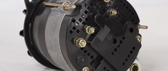
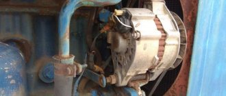
First you need to figure out where the MTZ generator is located. It is located on the side of the crankcase and is mounted on a rotating base. At the top point, the generator belt is fixed, which transmits torque.
A strap is also needed to rotate the coolant container. If it breaks, the operation of all systems automatically stops.
At the ends of the generator cover there are holes for air injection.
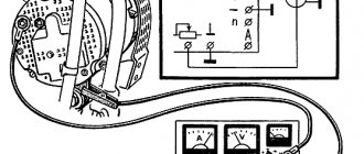
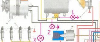
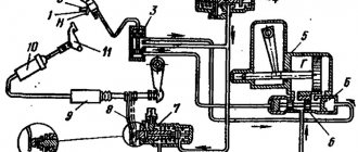
The diagram from the service manual looks like this:
The heart of the unit is the stator. Inside it there is a core made of stamped plates with a winding.
The winding forms phases connected in series in a delta circuit. The stator contains a bearing with a fixed shaft. It is pressed into a package of stamped plates. Supports are built into the removable covers. The shaft toe is equipped with an impeller-fan for active cooling.
The unit is equipped with excitation coils. They are supplied with current from the battery, which puts the system into operation.
If there is no battery in the equipment, then you can switch the generator to parallel excitation mode. In this case it will work independently.
By the way, for this reason the generator is called self-exciting.
So, the principle of operation is as follows:
- First the rotor starts. With its oscillations, it creates a magnetic field that affects the stator.
- Electromagnetic pulses create a three-phase alternating current in the stator, which is subsequently inverted into direct current. In some variations, it is necessary to connect an additional relay.
Generator connection diagram
So, every tractor driver needs a wiring diagram for a car generator in order to put it into operation directly “in the field”.
Process description
Connecting the MTZ 80 generator is a simple procedure. It is done in several stages:
- The generator is bolted to the side of the engine.
- Then the belt is tensioned and finally secured with a bolt.
- Then you need to connect the electrical. It is attached using the standard “terminal-bolt” method. Here is the generator wiring diagram.
How to check the generator at MTZ? You need to turn the ignition key. If the red light comes on, it means an error has been made. She talks about insufficient charge. You need to check the connection diagram again.
Winding check
The generator on the MTZ 82 still does not start; perhaps the problem is not in the connection, but in the winding itself. Then you will need to diagnose the system.
To do this, you need to disconnect the generator from the engine and fully charge the battery. So, you need to throw a minus on contact M, and a plus on W.
If the coil is working properly, the light bulb will burn very dimly. Bright light indicates serious problems.
Additional tests may also be needed:
- The minus is on M, and the plus is on B. It is necessary to include an indicator light in the circuit. If all is well, it will not burn. In the event of a breakdown of the diode or the positive terminal on the housing, the indication will be noticeable.
- Minus for any AC voltage contact, and plus for the B-block. The result, as before, is determined by the light bulb.
- Positive for M, and negative for variable contacts. If the lamp is on, it means there is a breakdown in the diode.
It will also not be superfluous to make sure that the light bulb itself is working. Sometimes it doesn't light because it's broken.
Wiring diagram MTZ 82(80) with large and small cabin with description
Belarus tractors are equipped with single-wire electrical equipment designed to start the engine, operate external light and sound alarms and additional components. The color diagram of the MTZ-82 electrical equipment attached to the technical documentation with a description allows you to determine the purpose of the wiring cables and restore the integrity of the circuits in the event of a breakdown.
Maintenance of devices at MTZ
To ensure that the controls and the generator itself do not fail, it is better to carry out regular maintenance.
First of all, it is necessary to regularly remove the oil and dust that settle under the lid. It is better to blow off the dust with a compressor, but ordinary rags will do. If dirt has clogged the cracks, disassembly and wiping will be necessary. You need to do it with the same rag soaked in gasoline. You should not use cotton wool or synthetics for cleaning.
You need to regularly inspect the terminals for oxides. As soon as they appear, they must be removed mechanically with sandpaper or a file. You should act carefully, just to remove the oxide film. You can also lubricate the contacts with copper or silicone grease.
Inspect the impeller and pulleys periodically. Any cracks or chips indicate an imminent major overhaul. It is better to replace them immediately to avoid emergency situations. Likewise, it is recommended to check the belt tension.
Frequent problems and their diagnosis
1 So, the control light does not go out, what should you do? Do not panic and immediately check the belt tension. If it is in order, then you need to check the contacts for oxides. If performance is not restored after cleaning, you need to check the output voltage. It should not be lower than 12.5 volts.
2 If you hear extraneous noise and knocking during operation, the problem is the loosening of the pulley fixing nut. However, bearing failure is also possible. Diagnosed by routine disassembly. The bearing will noticeably crunch when worn and will need to be replaced. The nut can be lubricated with thread sealant and tightened more tightly.
The main thing is that the fit on the pulley is not disturbed. You can notice a broken seat by the free movement of the nut. In this case, it needs to be replaced.
3 Under no circumstances should the bearing be knocked out. The shaft can be damaged, and this is a major repair. A special puller is required.
Otherwise, other generator breakdowns rarely occur on MTZ tractors.
Source
Maintenance and repair
Maintenance of the electrical components of the MTZ-82 tractor consists of carrying out routine maintenance and checking the condition of cables, instruments and incandescent lamps. The batteries are wiped from dust and traces of electrolyte, the liquid level in the banks is checked, and recharging is performed. In the generator, the field windings are checked, as well as the rectifier unit and the windings on the stator.
The voltage regulator used on the tractor is equipped with a seasonal switch. The manufacturer recommends checking and adjusting the voltage value at the regulator output. The unit is configured on equipment or on a special stand.
The electric starter is serviced after 3000 hours of diesel engine operation. The electric motor is removed for disassembly, followed by cleaning the commutator and checking the condition of the brushes. At the same time, the condition of the electromagnetic relay and the gear in contact with the ring gear of the diesel flywheel is monitored.
During operation, contamination of the high-voltage wire running from the magneto to the spark plug is not allowed. The magneto is serviced after 960 hours of engine operation; during the inspection of the unit, the components are cleaned of contaminants and the gaps between the breaker contacts are adjusted. At the same time, the spark plug is unscrewed and the gaps between the contacts are checked.
Models of generators for MTZ-82
The electrical system included several modifications of generators:
- Until the end of the second quarter of 1975, the production equipment used a G304-D1 modification unit equipped with a PP362-B relay regulator. The generator is distinguished by the location of the switching terminals on the rear of the housing.
- From the second half of 1975 (according to some sources - from the beginning of 1976), the G306 model unit began to be used, working in tandem with the PP362-B voltage regulator.
- In the 80s The G309 modification unit began to be used, characterized by increased power and increased service life of parts. Some machines used the 700-watt G464 generator, which was supplanted by the G964 product (and its modifications), which had a power of 1000 W.
- Since the beginning of the 2000s. a unit model AT 1150.04.1 was introduced (or an analogue with serial number 9695.3701-1), which has an 11% increase in output and an improved voltage corrector. On tractors with air conditioning and a D-245 diesel engine, unit 9702.3701 is used, capable of generating current up to 100 A (power is 1400 W).
MTZ generator and its device
There are two types of mechanisms - direct and alternating currents. The first type MTZ generator consists of:
Force is generated in the cores with the winding. When equipment moves, magnetic fluxes increase. The semiconductor diode is a rectifier. The constant production of voltage by the tractor generator is regulated by a special automatic system.
Current is carried in only one direction. Tractor generators of the second type are capable of operating without voltage regulators. A rectifier is required to charge the battery.
The alternating current MTZ generator consists of the following elements:
- Stator;
- Rotor;
- Back and front covers;
- Bearings.
There are six cores in the tractor generator housing. The elements are made of iron plates. The copper winding is fixed to the core. Each has 63 turns. The ends of the winding are connected to the terminals.
The MTZ generator has a switch. A wire and terminals are attached to it. To ensure normal operation of the tractor generator, it is necessary to connect lamps of suitable power. The mechanism has three working positions.
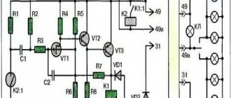
Electrical diagram of tractor MTZ 82 1
There is also a rear suspension, which is carried out using two hydraulic cylinders for lifting the blade, hinged to two eyes of the clamp on the main frame of the motor grader, and ball joints of the transverse beam of the traction frame.
GAZ and 3IL with diesel Typical malfunctions of alternating current generators: Covers: contamination and wear of oil seals and bearings, bearing seats, deformation of steel sealing washers of bearing units, thread failure. Almost all vulnerable elements of electrical equipment have fuses that reliably protect them from voltage surges.
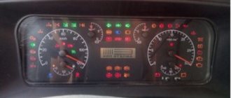
Instrumentation: diesel coolant temperature indicator; current indicator ammeter; indicators for oil pressure in the diesel lubrication system, oil pressure in the gearbox control hydraulic system, air pressure in the pneumatic system; tachometer; fuel level indicator, air filter clogging indicator. The engine starts due to the fact that power comes from the battery.
To do this, you need to perform the following steps: dismantle the starter; remove the casing that performs protective functions; check the brush-commutator assembly. Pay special attention to the cleanliness and fastening of wires. These parts are called the tractor mass, to which the negative terminals of electrical energy sources are connected.
Related article: starter connection diagram for MTZ-80
It is located on the control panel in the operator's cab. With the engine running Belarus MTZ One of the advantages of Minsk technology is the use of high-quality electrical wiring, based on the fact that metal parts are designed to act as mass. The lighting and light signaling system consists of headlights and work lights, taillights, side lights, turn signals, brake lights, reversing lights and various relays for controlling them.
Connection to the socket is made via a plug. The starter requires cleaning every hour of use. Pay special attention to the cleanliness and fastening of wires.
Starter in the tractor electrical circuit
The wires are assembled into bundles, mounted and connected using special mounting and installation devices: connecting panels, plug connectors, etc. However, the battery produces direct current, so the alternating current of the generator, before entering the circuit, is passed through a three-phase silicon circuit built into the generator The rectifier is assembled using a bridge circuit and is converted into a constant one. Transmission of the MTZ 82 tractor The transmission is designed to transmit torque from the diesel engine to the drive wheels of the tractor, power take-off shafts, as well as to change the magnitude and direction of revolutions and transmitted torque. Acid-resistant mastic is poured into the cavity between the lid and the tank. The exclusive right is reserved by the author of the text.
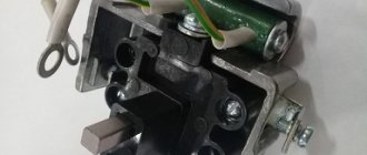
The set of control and measuring instruments includes indicators and sensors for charge-discharge current, on-board network voltage, temperature, oil pressure, fuel level in the fuel tank, tractor speed, engine speed and engine hours. The advantages of such MTZ electrical wiring include: reduced number of wires; simplified approach to maintenance. Compressor; apparatus for authoring and testing emergency spark plugs; MTZ, MTZ Sound signal: 1 - signal button, 2 - rod, 3 - breaker, 4 - electromagnet core, 5 - armature, 6 - body, 7 - membrane By pressing button 1, the signal circuit is closed; electric current passing through the winding magnetizes core 4, which attracts armature 5. How to connect a turn relay on a tractor
Design and operating principle
The unit is mounted on the side of the engine crankcase on a rotating base; the upper fixation point allows you to adjust the tension of the drive belt. Torque is transmitted from a pulley mounted on the toe of the crankshaft using a segment key. The belt also rotates the pump of the liquid cooling system; if the drive breaks or the generator rotor is jammed, further operation of the tractor is impossible. The end covers of the housing have shaped channels for supplying air and draining water entering the internal cavities of the product.
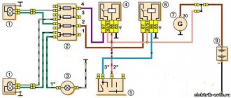
Generator connection diagram
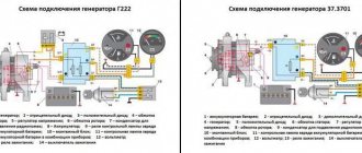
The connection diagram of the generator to the tractor's on-board network does not depend on the equipment model.
The design provides 3 or 4 outputs:
- point B or + is used to switch the positive wire from the battery;
- block M is connected to the negative pole of the battery;
- connector D (used on new versions) passes through the charging indicator device and the ignition switch to the positive output of the battery;
- plug Ш is brought out to the tractor body (negative pole);
- point W is found on part of the generators and is connected to the tachometer.
Process description
The generator is mounted on the engine, then the belt tension is adjusted, after which the upper fixing bolt is tightened. The wiring is connected to the terminals located on the rear of the unit, in accordance with the electrical diagram of the tractor. If the switching is incorrect, the generator will not work; when you turn the key in the lock, the red no-charging lamp should light up. After starting the engine, the indicator automatically turns off, indicating the correct operation of the battery charging system.
Winding check
The winding test is carried out with the motor turned off and the cables disconnected from the generator. For testing, you need a test light and a charged 12 V battery. To check the excitation coils, you should apply negative power to block M, and connect the positive plug of the battery through a lamp with connector Ш. When the coil is working, the current in the circuit drops, the lamp burns dimly.
Full heat indicates a breakdown between the windings and the generator casing, and the absence of glow indicates a coil break.
Additional tests to check the stator winding and rectifier:
- Apply a negative signal to point M, and connect the positive pole to terminal B, connecting a test lamp to the circuit. Under normal conditions, the indicator does not light; if the diodes are damaged or the positive output to the body of the electrical machine is broken down, the lamp will turn on.
- Apply negative power to any AC contact (before the rectifier), and connect the positive wire to block B through the test light. If the rectifier is working properly, the lamp will not turn on; if the diodes of straight polarity break down, it will light up.
- Connect the positive terminal to the AC connectors, and connect the negative terminal to terminal M. If the lamp is on, then it is necessary to replace the reverse polarity diodes. There is also a short circuit between the stator winding and the generator housing.
Electrical wiring MTZ
Questions can only be asked after registration. Please login or register.
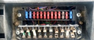
Hello! Please tell me how to connect the electrical wiring to the MTZ 82 (launcher). It is enough that the battery is charging and the headlights are on. I took the tractor with completely destroyed wiring; only the headlights from the generator were connected. Now I have installed a battery and a fuse box from a VAZ-2106. I don't know how to combine the generator with the battery. Thank you in advance.
This is roughly how fuses can be made for each lamp or one for the entire circuit Files: 82p.preview.jpg
Thanks a lot. Should I install the ammeter + from the battery and from the generator on different terminals?
Thanks a lot. Should I install the ammeter + from the battery and from the generator on different terminals?
On the ammeter, the wire from the battery is connected to the terminal with a minus sign. And the wire from the generator and the supply wire to consumers to the terminal with the plus sign.
Signs of stator winding malfunction
To begin with, it would be nice to know what connections are used for this device. This is a simple matter: the negative wire of the battery is attached to the “M” terminal of the generator, and the positive wire is connected to the “W” terminal through a test lamp.
- As mentioned above, if the winding is faulty, the indicator light on the dashboard will not light up, or will light up very weakly. In addition, the current strength will not exceed 3-3.5 amperes.
- If the light does not light up at all (regardless of the modification of the tractor engine), then the winding is simply torn, rotted, or oxidized (it must be emphasized).
- We change the connection. We connect the minus terminal of the battery to any terminal of the generator, and the plus terminal again through the indicator light to terminal B of the generator.
Mazda 6 2.0 AT hatch › Logbook › Installing an Ammeter. Part 1 Found a suitable one. Disassembly. Preparation.
If there are no problems with a Voltmeter for a car (there are plenty of options), then with Ammeters for a car theme it’s not so easy...
History of the issue. An ammeter is a device that shows the direction and strength of the current - charge or discharge of the battery. You can perfectly evaluate the operation of the generator, the state of charge of the battery, etc. Having a voltmeter and an ammeter can detect many problems with electrical equipment, especially with the generator and battery.
Ammeter - you need to cut into the wire - from the battery to the generator (this was the case on Soviet cars). True, those instruments showed the direction of the current, but the value was very approximate.
To organize a digital ammeter, a different approach is now used. A calibrated conductor is installed in the circuit break - a SHUNT with a certain resistance. By measuring the potential difference at the ends of the shunt, the current passing can be determined. It's simple.
The only problem turned out to be that most circuits for measuring current in both directions require installing a shunt in the circuit from the MINUS of the battery. The circuit is attached to any such ammeter
Here is an example of how this ammeter can be implemented in the charging circuit from a generator. It is necessary to organize separate meals. www.drive2.ru/c/2569118/
In principle, you can find a circuit with a 500A shunt... BUT. Another inconvenience - in our car there is a negative wire - connected to the body several times. places. Also - made an addition. minus... Well, ruin everything...
We managed to find a device with a shunt installed - in the POSITIVE circuit. Which is much easier. Because from the battery positive - one wire goes to the starter (for powerful current at start-up), and the other goes to all consumers of the car through the main 120A pre. Connection - screw. Convenient to attach. A measuring shunt can be installed in this circuit.
Ammeter - has “our”