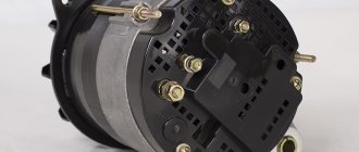
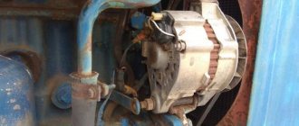
Design and principle of operation of the generator
Before finding out the size of the alternator belt, it is necessary to study this element, its design and operating principle in more detail. Despite the fact that different types of generators were installed on MTZ tractors, they are absolutely identical in their performance indicators and features.
This element has an identification number, which may vary and depends on the modification used:
- G306-D;
- G-306A;
- G-304A.
The generator is an important part in technology.
For its correct operation, the presence of direct current seems to be a necessary requirement. The design of the generator involves the passage of current through a three-phase rectifier, which allows it to be transformed from alternating to direct.
The characteristics of the generator are determined by the operation of its main elements, which are the stator and rotor. The first is made from sheet steel, as well as a three-phase coil mounted on a special protrusion. The rotor is a star-shaped element with 6 angles, mounted on a shaft. The principle of operation is extremely simple : using a V-belt, the rotation of the crankshaft is transmitted to the generator pulley. Due to the rotational movements of the rotor mechanism, an electromagnetic field is created, which, under the action of the windings, leads to the appearance of a current passing through the rectifier.
Essential elements
When planning to buy a generator at MTZ 82 for its subsequent installation, you need to familiarize yourself with its design in more detail. As mentioned earlier, its basis is the stator and rotor, but there are many other elements that ensure the correct operation of the unit. Among them, worthy of mention:
- front, rear cover, and regulator protection;
- rectifier, insulator, coil and fan;
- adjusting and fastening elements;
- rotor and spacer bushings.
Be sure to read: Tractor brands
Knowing what elements the design of such a device consists of, it will be much easier for the owner of an MTZ tractor to install it themselves or carry out repairs, which will reduce the cost of specialist services.
Generator circuit
How to test a generator with a multimeter
Asynchronous motors are often used as generators. This is caused by the presence of residual magnetization of the shaft. The drum under the squirrel cage is cast from light alloy, the axis is pure ferromagnetic material. As a result, after stopping the electric motor, the shaft often remains magnetized. Below we will explain how to check the generator with a multimeter, we will talk about ways to start the motor, achieving electric current.
Electric generators
Most modern electrical generators operate on the basis of Faraday's law for emf, which states that a voltage appears in a conductor that is proportional to the area and rate of change of magnetic flux. In addition, the specified value is multiplied by the number of turns. We immediately see ways to increase the voltage:
- Increase the coil winding area.
- Increase the rate of change of magnetic field flux:
- Due to an increase in the rotor excitation current or stronger permanent magnets.
- By increasing the rotation speed.
Electric generator
If we take industrial generators, the first method is mainly used. This is due to strict requirements for the generation frequency. As for the coil area, the parameter is set structurally; changing it is problematic. The purpose of describing the simplest information: there are many examples on the Internet where they are trying to start electric motors as generators. Some attempts are not very successful, and the authors clearly demonstrate ignorance of the simplest laws of physics.
So, the advantage of synchronous generators is constant frequency - often this is the main requirement. The speed of the motors, the normal operation of the filtering circuits, etc. directly depend on the voltage parameters. If the voltage is incorrect, first of all you need to check the generator voltage regulator by comparing it with the readings of the multimeter. Now imagine what will happen if the power frequency increases twice. Yes, certain types of asynchronous motors with a squirrel-cage rotor, in addition, commutator motors react primarily to amplitude. So what is next?
Note:
- When checking the generator voltage with a multimeter, estimate the potential difference between the output (main) sockets (terminals) without taking into account the ground line.
- When checking the alternator is charging, take a measurement at the 12V DC jack.
It is suggested to choose the right power source for the equipment. And in the described case, this knowledge is important for the reason that the design of synchronous and asynchronous generators is different. Therefore, verification methods must take this fact into account. Let's briefly consider the types of alternating current generators.
Generator connection
Connecting this element to the electrical network of MTZ tractor equipment may seem like a difficult task for an inexperienced user, but to successfully complete it, it is enough to follow a number of simple recommendations:
- Connect the “+” wire from the battery to terminal “B”.
- Connect terminal “Ш” to the relay regulator.
- Terminal “M” must be connected to the tractor body.
It is necessary to be guided by the connection diagram, which contains the main elements of the electrical network, for example, a battery, which will allow you to avoid errors when performing work.
Connection diagram
Using the connection diagram, the technician can easily determine the main elements of the tractor’s electrical network, as well as their location. The most significant objects in the diagram include the generator itself, a resistor, a capacitor and ignition switch contacts, a battery, a warning lamp and windings.
Voltage regulator Ya112B
The voltage regulator, as in other generators, turns the excitation current on and off. If the voltage rises, he turns off the excitation current, the voltage decreases, he turns on the excitation current and the voltage rises again, he turns off the excitation current again, thus maintaining a stable voltage level of about 14 Volts.
Initial excitation is possible without a battery.
The Ya 112 B regulator is distinguished by the fact that it is guaranteed to pass excitation current, even at very low voltage values at the generator output, which ensures reliable excitation of the generator without a battery.
The rotor contains permanent magnets that create a strong enough magnetic field to excite the generator.
After the generator is excited, part of the winding current is diverted through an additional rectifier to the excitation winding; for this, the output of the additional rectifier is connected at point D of the voltage regulator. The excitation current goes through point D to the excitation winding and further through point W and the open transistor of the regulator to ground.
Device Maintenance
Thanks to the successful design of such elements, they can operate for a long time without the need for repair work, even in difficult conditions, for example, in the presence of a large amount of dust and heat. The generator demonstrates stable operation even at high speeds, which indicates its reliability.
But even the most durable device requires care and maintenance, which will extend its service life and avoid the need to repair the MTZ 80 generator yourself. You should check the fastenings of the element, as well as the degree of tension of its belt. The deflection should not be more than 3 cm; if such indicators are exceeded, it is strongly recommended to tighten the belt.
It is necessary to regularly carry out troubleshooting of the product, which will allow timely detection of the presence of cracks, as well as other damage that could disrupt the correct operation of the unit. The electrical connections of the generator should be regularly cleaned when oxidizing, after disconnecting them from the battery.
Be sure to read: MTZ 82: valve adjustment
Models of MTZ tractor generators
The evolution of MTZ tractor models and the increase in the equipment of machines with electrical equipment led to the use of generators of a similar design with higher power and corresponding technical characteristics. Modern MTZ machines with a network voltage of 12 volts are equipped with units of the following series: G46.3701 with a power of 700 W; G96.3701 with an output power of 1000-1150 W and G 97.3701 with a power of 1400 W. For MTZ machines with a network voltage of 24 volts, units of the G99.3701 series with a power of 1000-1150 W and 98.3701 with a power of 1500 W are installed. Modifications of units differ in the design and size of the drive.
Checking proper operation
To be confident in the unit you are using, it is advisable to check its functionality before each use. For this purpose, a special control lamp is used. When the tractor ignition is activated, it should light up, and when the engine starts successfully, it should go out immediately.
The lamp can only turn off after increasing the crankshaft speed. If this does not happen, we are talking about the presence of malfunctions in the operation of the generator. To do this, turn off the engine and then follow the following instructions:
- Check the tension level of the alternator belt and adjust it if necessary.
- Connect the negative wire from the battery to terminal “M” and the other to terminal “B”.
- Turning on the lamp at this stage indicates a malfunction of the rectifier.
- Next, the “-” from the battery will need to be connected to the AC terminal, and the “+” to the “B” terminal. If the lamp lights up, the rectifier diode is broken down.
You can also combine the “+” from the battery with the AC terminal, and the “-” with the “M” of the generator. When the lamp is turned on, the problem most likely lies in a short circuit in the stator winding or a broken diode.
Care should be taken when working with electrical components, as they can quickly become unusable if not handled correctly.
Signs of stator winding malfunction
To begin with, it would be nice to know what connections are used for this device. This is a simple matter: the negative wire of the battery is attached to the “M” terminal of the generator, and the positive wire is connected to the “W” terminal through a test lamp.
- As mentioned above, if the winding is faulty, the indicator light on the dashboard will not light up, or will light up very weakly. In addition, the current strength will not exceed 3-3.5 amperes.
- If the light does not light up at all (regardless of the modification of the tractor engine), then the winding is simply torn, rotted, or oxidized (it must be emphasized).
- We change the connection. We connect the minus terminal of the battery to any terminal of the generator, and the plus terminal again through the indicator light to terminal B of the generator.
Tractors are equipped with inductor generators, which are better adapted to difficult working conditions.
Dust, dirt, poor cooling (low speed during operation)
Almost continuous operation during the working day
An inductor generator differs in that its rotor does not have an excitation winding and is simply a rotating magnetic circuit. When rotating, the rotor creates a changing magnetic field, and an emf is induced in the winding.
The generator has a stationary
excitation winding, direct current passes through it, from the generator, this current creates a strong magnetic flux, which closes through the rotating rotor.
The field winding terminals are connected so that the field current flows in the direction of magnetization of the rotor, which contains permanent magnets. If the leads of the excitation winding are mixed up, the excitation current will demagnetize the rotor and the generator will practically stop working.
The fact that the field winding does not rotate with the rotor provides an important advantage - brushes are not needed to transmit current to the rotating rotor. The brushes wear out, poor contact under them greatly reduces the reliability of the generator, so an inductor, brushless generator is more reliable.
The single-pole magnetic circuit and large magnetic gaps in the excitation system reduce the efficiency of the inductor generator compared to a classic automobile generator, where the excitation winding is inside the rotor and current is supplied to it through brushes.
A decrease in efficiency leads to a deterioration in weight and size parameters, but for tractors and heavy vehicles this is a less important quality than reliability and durability.
An alternating EMF is generated in the winding of the inductor generator, therefore, a rectifier is needed at the output of the winding - a diode bridge. Depending on the generator circuit, a three-phase or five-phase diode bridge can be used, with or without additional diodes.
An important requirement for tractor generators is that they must operate both with a battery and without a battery. For example, if the engine is started by a starter, without an electric starter, then the battery becomes unnecessary or unnecessary.
A conventional automobile generator is always excited by a battery, but a tractor generator must be provided with excitation without a battery. To reliably excite the generator, the rotor has residual magnetism, and the voltage regulator provides appropriate changes in the circuit to facilitate self-excitation.
Generator 46.3701 Made according to a circuit with a five-phase winding,
respectively with a five-phase diode bridge with additional diodes.
The five-phase circuit makes it possible to obtain higher quality rectified voltage, that is, with less ripple. This is relevant in the absence of a battery, which, like a filter, smoothes out the ripples of the rectified voltage.
The use of a circuit with additional diodes is justified by the fact that an external excitation circuit is not needed; it is closed inside the generator. In addition, if there is a battery, powering the excitation winding from additional diodes prevents accidental discharge of the battery through the excitation winding when the power is on and the engine is not running.
Maintenance of devices at MTZ
During operation, oil particles and dust accumulate on the generator, which should be removed with a clean rag. If dirt has accumulated in the internal cavities of the equipment, the unit must be removed for disassembly and cleaning with a rag moistened with gasoline. The formation of a layer of oxides on the terminals or destruction of the insulation of the wires of the tractor on-board network is not allowed.
When starting the engine, the control lamp should go out (on some tractors the indicator is allowed to blink in idle mode; when the frequency increases to 1400 rpm, the lamp turns off).
Do not operate equipment with a damaged pulley or fan impeller. It is recommended to periodically check and adjust the belt tension (deflection arrow 30 mm with a load of 3 kg). An over-tensioned drive will overload the rotor bearings. Due to wear of the elements, the normal clearance between the rotating unit and the stator is disrupted. Cracks or tears in the belt cause the drive to slip.
