- home
- Media center
- Articles
- PZD KAMAZ - engine pre-heater, operation diagram, characteristics
Menu
- News
- Articles
- Video materials
- Photo materials
- Publication in the media
- 3D tour
03.03.2020
The KAMAZ diesel engine is a diesel heater, which is necessary to warm up a cold engine. In addition, the device prevents glass from icing. The part operates autonomously from the engine. The mechanism is equipped with a liquid-type cooling device. Warming up is carried out by heating the liquid by the PZD mechanism. Let's consider the structure of the heater, as well as the design and principle of its operation.
Features and purpose of the heater
Many car owners know that a diesel engine does not always start if the ambient temperature drops to -15...-20°C. This is due to the fact that in the cold, oil and fuel turn into a viscous substance, which “slows down” the operation of the crank mechanism. To prevent the problem, use a pre-heater.
PZD KAMAZ is a device with which the engine is heated to the required temperature. In KAMAZ vehicles, the device is used to start the engine at temperatures from -20°C and below. The heaters use diesel fuel, so they provide quick heating.
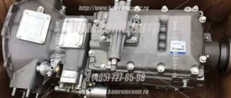
KAMAZ trucks models 4310, 5320 were equipped with PZD-30 - a simple but reliable design. The productivity of the unit was up to 30.2 kJ of heat per second. Similar devices continue to be produced to this day.
Modern trucks are equipped with heaters 15-8106. Units of type 14TS-10 are also widely used.
Pre-start liquid heater PZD 16-01ST. Repair manual PZD16-01ST RR
Transcript
1 LLC "Thermal Systems" Russia, Republic of Tatarstan, Naberezhnye Chelny, st. Profilnaya 32a 8(8552) ; website: Pre-start liquid heater PZD 16-01ST Repair manual, Naberezhnye Chelny 2015.
2 2 PZhD16-01ST RE Contents 1 Introduction 3 2 Technical characteristics Safety precautions Design and designation of the main components of the heater. 4 5 Possible malfunctions and methods for their elimination Purpose, repair and replacement of heater components Checking and replacing the glow plug Dismantling and replacing the spark plug grid Checking, dismantling and replacing temperature sensors Checking, dismantling and replacing the flame indicator Purpose, dismantling and replacing the air blower Purpose, dismantling and replacing the combustion chamber Purpose, dismantling and replacing the heat exchanger Dismantling and replacing the circulation pump (pump) Dismantling and replacing the fuel pump Dismantling and replacing the control unit Description of the heater operation Checking the heater after repair Manufacturer's guarantees 28
3 3 1 Introduction This repair manual (RR) is intended for personnel involved in the maintenance and repair of pre-start diesel heaters PZD 16-01ST. It contains a method for identifying faults, as well as methods for determining the suitability of heater components and parts and the need to replace them. The manual contains basic technical data, a description of the components and their purpose as part of the heater, and provides recommendations for their maintenance and repair. The manual describes the main distinctive features of the model. When repairing the heater, it is necessary to additionally use the operating manual, passport, catalog of parts and assembly units. The repair manual may not reflect minor design changes made by the manufacturer after this RR was signed for printing. 2 Technical characteristics Technical characteristics are given with a tolerance of ±10%, obtained at a temperature of +20ºС and a rated voltage of 24V. Table 1 Parameter Value 1 Heating capacity, kW - full mode - middle mode 2 Fuel consumption, l/hour - full mode - middle mode 3 Rated supply voltage, V - rated - operating lower - operating upper 16.5 10 2.0 1, 15 4 Fuel used Diesel according to GOST Coolant Antifreeze, antifreeze 6 Power consumption of the heater, W, no more - full mode - medium mode 7 Current consumption in the off state, mA 10 8 Weight of the heater assembly, kg 7.12 9 Weight of the heater, s components, kg
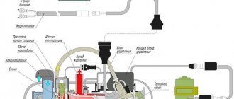
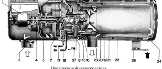
4 4 3.Safety 3.1 When repairing, you should follow the current labor protection instructions. 3.2 Violation of the rules for operating the heater may cause a fire. 3.3 The workplace must be provided with fire extinguishing means. 3.4 Using the heater when the cooling system is not filled is strictly prohibited. 3.5 It is prohibited to turn on the heater without fuel. 3.6 Refueling with fuel while the heater is running is prohibited. 3.7 The heater may only be used for the purposes specified in the instruction manual. 3.8 When carrying out welding work on a car or repair work on the heater, it is necessary to disconnect it from the battery. 3.9 The heater must not be used in places where flammable vapors and gases or large amounts of dust can form and accumulate. It is prohibited to operate the heater in closed, unventilated areas. It is prohibited to connect the heater to the electrical circuit of the car with the engine running and no battery before the first start or a long break in the operation of the heater. , fill the heater fuel supply system with fuel. It is prohibited to turn off the power to the heater until the end of the purge cycle. It is prohibited to connect or disconnect the heater connector when its power supply is turned on. After turning off the heater, it must be turned on again no earlier than after 10 seconds. In the event of a flame appearing at the outlet of the exhaust pipe, turn off the heater and after stopping it, begin troubleshooting. 4. Design and principle of operation 4.1 The main components and parts included in the package of the pre-heater PZhD 16-01ST are shown in Figure 1 and the electrical connection diagram of the heater is shown in Figure 3.
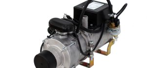
5 5 Fig.1 Main components of the PZD 16-01ST heater Fig.2 Complete set of the PZD 16-01ST heater
6 6 Fig.3 Electrical connection diagram of the PZD16-01ST heater 5. Possible malfunctions and methods for eliminating them 5.1 Replacement of the following elements of the heater, in case of failure, can be done without removing the heater from the car: - circulation pump; - fuel pump; — control unit; — air blower; — glow plugs; — temperature and overheating sensors; — flame indicator.
7 7 5.2 The cause of a malfunction of the PZD 16-01ST heater, with the exception of loss of housing tightness or loss of thermal conductivity of the heat exchanger, is determined by the malfunction code displayed on the heater control panel in the form of flashing LED indicators (see Table 2). Table 2. Number of blinks Indicator malfunction 1 Inadmissible supply voltage 2 No start, flame failure 3 Overheating 4 Spark plug malfunction 5 Centrifugal pump malfunction 6 Flame indicator malfunction 7 Temperature sensor malfunction 8 Air blower malfunction 9 Dosing pump malfunction 10 No purge 5.3 Characteristic Malfunctions and methods for eliminating them are given in Table 3. Table 3. Description of the malfunction Elimination methods Check the vehicle battery and electrical wiring. The voltage between 4 Inadmissible voltage and 7 pins of the XS1 connector must be no higher than 30V and no lower than 20V. If the permissible number of start attempts has been used, check the quantity and supply No fuel starts. Check the combustion air supply system and the exhaust pipe. Check fuel supply. Check the combustion air supply system and the exhaust pipe. No flame. Check the flame indicator and replace if necessary. Check connecting wires. Check indicator malfunction ohmic resistance between the contacts of the indicator flame, which should be no more than 1 Ohm Malfunction of the dosing pump Malfunction of the centrifugal pump (pump) Check the reliability of the connector connection, check the pump for performance, replace if necessary. Remove air from the vehicle's fluid circuit. Check the electrical wires of the circulation pump for short circuits, check the circulation pump for functionality, and replace if necessary.
8 8 Description of the malfunction Malfunction of the air blower Malfunction of the spark plug Malfunction of the temperature sensor Overheating Continuation of table 3 Elimination methods Check the electrical wiring of the air blower motor, if necessary, replace the electric motor. Check the glow plug and replace if necessary. Check the connecting wires and replace the sensor if necessary. Check the complete fluid circuit and the operation of the circulation pump. 6. Purpose, repair and replacement of heater components The PZD 16-01ST heater assembly is shown in Figure 4. Fig.4 PZD 16-01ST heater assembly 6.1 Checking and replacing the glow plug. The glow plug serves to pre-ignite the air-fuel mixture during start-up mode. Check the functionality of the spark plug as follows: - disconnect the wires of the glow plug, pos. 1, from the control unit connector, pos. 2, remove the rubber plug, pos. 3, remove the spark plug, pos. 4, pulling with slight force the free end of the spark plug, Figures 5, 6 and 7 - connect the spark plug to a DC source with a voltage of 12-0.3 V and after 15 seconds measure the current consumption.
9 9 The current consumption should not exceed 5.0A, and the end of the spark plug will heat up to a bright red color. Test time is no more than 120 seconds. The time interval between switching on is at least 180 seconds. If current consumption exceeds 5.0 A or if the plug does not glow at the end and does not heat up to a bright red color, the plug must be replaced. Install the glow plug as follows: - visually check the location of the retaining ring, pos. 5, in the groove of the glow plug body; if necessary, pre-press the retaining ring with pliers. — insert the candle into the burner device with little force until a characteristic click is heard. — replace the plug pos. 3 and connect the glow plug wires to the corresponding connector of the control unit pos. Fig. 5 Removing the glow plug electrical wires. 4 3 Fig.6 Removing the rubber plug.
10 Dismantling and replacing the spark plug grid. Fig.7 Removing the glow plug The spark plug is designed to uniformly supply fuel to the combustion chamber. After replacing the glow plug, it is necessary to clean the air channel hole Ø2.5 (see Figure 8), conduct a test run of the heater, in case of uneven operation (intermittent hum) or unsuccessful start (no flame number of blinks 2 indicators of the control panel, see error code in table 2), it is necessary to replace the glow plug grid. Dismantle the spark plug grid as follows (see Figure 8): - remove the spark plug; — dismantle the bushing; - remove the mesh. Install the spark plug grid in the reverse order. WINMANY! The spark plug grid must be installed with an interference fit into the combustion chamber evaporator, but with little force, preventing deformation of the combustion chamber evaporator. Control the size of 6 mm (see Figure 8).
11 11 Fig. 8 Installation diagram of the glow plug and spark plug grid 6.3 Checking, dismantling and replacing temperature sensors. Temperature sensors are used to monitor the temperature of the heated liquid, as well as to control the heating temperature of the heat exchanger. Technical data of the temperature sensor: - voltage output signal; — the law of change of the output signal is linear, the signal value increases with increasing temperature; — temperature range from -50⁰С to +150⁰С The resistance of the sensor depending on the temperature is described in Table 4. Table 4 Temperature, ⁰С Nominal resistance of the sensor, com Minus .7 2.619 2, .473 0.453 0, .399 0.381 0, .339 0.323 0.345 Permissible sensor resistance value, com Temperature sensors are non-repairable and maintenance-free products. The failure criterion is considered to be a deviation of the sensor parameters of more than 10% from the nearest extreme value. Dismantle the temperature sensors without draining the coolant from the system as follows (see Figures 9, 10,11 and 12): - disconnect the wires of the temperature sensors pos. 1 and 2 from the connectors of the control unit pos. 3; — unscrew temperature sensors pos. 4, 5 from the heater body. Install the temperature sensors in the reverse order; the tightening torque of the sensors is 6–7 Nm; when connecting the wires to the control unit, polarity is not required.
12 Fig.9 Removing the temperature sensor wires 4 Fig.10 Location of the outlet temperature sensor
13 13 5 Fig. 11 Location of the inlet temperature sensor Fig. 12 General view of the temperature sensor 6.4 Checking, dismantling and replacing the flame indicator The flame indicator is used to determine the presence of flame in the combustion chamber. Check for functionality as follows (see Figure 13): - unscrew the screws securing the wires of the flame indicator, pos. 1, connector of the control unit, pos. 2; — using a multimeter, check the flame indicator for a short circuit; if there is no short circuit, dismantle and replace the indicator.
14 Fig. 13 Disconnecting the flame indicator wires Removing and replacing the flame indicator is carried out as follows: - disconnect the power supply connector of the electric motor, pos. 1, figure 14: - unscrew the 3 M8 screws, pos. 2, securing the supercharger, pos. 3, figure 15 and remove the supercharger; — unscrew the M2.9 screw securing the flame indicator, pos. 4, Figure 16, and remove the indicator. Install the flame indicator in the reverse order; when connecting the wires to the control unit, check the location of the wires according to the black mark, pos. 3, Figure 13 (the wire with the mark must be connected to the outer socket of the control unit connector) 1 Fig. 14 Electric motor power connector
15 Fig. 15 Dismantling the supercharger of the PZD 16-01ST heater 4 Fig. 16 Location of the flame indicator mount Fig. 16 General view of the PZD 16-01ST flame indicator
16 Purpose, dismantling and replacement of the air blower. The air blower (see Figure 17) is used to supply air to the combustion chamber of the heater, to ensure the formation of an air-fuel mixture, stable combustion in all modes, as well as for purging the heater burner device after stopping and before starting the heater. Changing the amount of air flow is carried out by changing the voltage supplied to the air blower motor. If the electric motor or impeller fails (determined by the characteristic noise in the operation of the heater, as well as unstable operation with periodic attenuation, which is caused by low air flow pressure), the air blower may be subject to partial repair or replacement of its components. Dismantling the air blower and disassembling it is carried out as follows: - disconnect the power supply connector for the electric motor, pos. 1, figure 14: - unscrew the 3 M8 screws, pos. 2, securing the supercharger, pos. 3, figure 15 and remove the blower; — unscrew the M8 nut pos. 4 Figure 17 securing the supercharger and remove the supercharger with the bushings securing the impeller; — unscrew the 4 M5 screws, position 5, figure 19, securing the electric motor, position 6, and remove the electric motor. 4 Fig. 17 Air blower of the PZD 16-01ST heater.
17 17 Fig. 18 Supercharger with removed impeller and bushings 5 6 Fig. 19 Removing the electric motor
18 18 Fig. 20 PZD16-01ST heater electric motor Assemble and install the air blower in the reverse order. 6.6 Purpose, dismantling and replacement of the combustion chamber. An evaporative combustion chamber is designed to create and burn an air-fuel mixture. Signs of failure of the combustion chamber are considered to be increased smoke at the outlet of the heater. To dismantle the combustion chamber, proceed as follows: — drain the coolant from the vehicle cooling system; — remove the heater from the car; — disconnect the electric motor power connector pos. 1 Figure 14; — disconnect the power wires of the flame indicator pos. 1 figure 13; — dismantle the glow plug in accordance with paragraph 6.1 of this RR — loosen the clamp pos. 1 securing the fuel line pos. 2 and disconnect the fuel line (see Figure 21); — unscrew the 4 M8 screws, item 3, Figure 21, securing the injection unit to the heater boiler and dismantle the injection unit (see Figure 22); — unscrew the 3 M8 screws, pos. 2, and remove the supercharger, pos. 3, Figure 15; — unscrew the 4 M5 screws securing the burner device and dismantle the burner device (Figure 23).
19 Fig. 21 Dismantling the fuel line of the heater Fig. 22 Pressure block of the heater PZD16-01ST A Fig. 23 Burner device of the heater
20 20 Install the heater burner device in the reverse order; before installing it on surface A (see Figure 23), apply a thin layer of ceramic sealant DONE DEAL DD6785 (or equivalent), having previously degreased the surfaces with Acetone. 6.7 Purpose, dismantling and replacement of the heat exchanger. The heat exchanger (see Figure 24) is designed to transfer heat from the gas flow of combustion products in the combustion chamber to the coolant circulating in the liquid jacket of the heater. Malfunctions of the heat exchanger that may occur during the operation of the heater are loss of thermal conductivity as a result of deposition of diesel fuel combustion products, soot and soot on the internal walls and fins of the heat exchanger, as well as loss of tightness. A sign of loss of thermal conductivity of the heat exchanger is an increase in the temperature of the exhaust gases above +550⁰С (normal temperature +350⁰ +450⁰С). Dismantling of the heat exchanger is carried out as follows: - dismantle the discharge unit in accordance with paragraph 6.6 of this RR; — remove the heat exchanger from the heater boiler (Figure 25). Fig.24 Heat exchanger
21 Fig. 25 PZD16-01ST heater boiler Installation of the heat exchanger is carried out in the reverse order; if necessary, replace the sealing ring pos. 1, figure 25; before installing the heat exchanger in the boiler, check the uniform distribution of the spiral turns, pos. 2, figure. Dismantling and replacing the circulation pump (pump ). The circulation pump (Figure 26) circulates the heated liquid in the cooling circuit of the vehicle engine and in the liquid circuit of the heater. Main technical characteristics of the pump: - productivity 1400 l/h; — pressure difference between inlet and outlet 0.015 MPa; — current consumption no more than 1.8A;
22 22 Fig. 26 Circulation pump assembly If the working fluid (antifreeze, antifreeze) leaks through the pump seals or if the electric motor malfunctions, the pump must be dismantled and replaced. The circulation pump can be dismantled without removing the heater from the car. — drain the coolant from the car system; — disconnect the connector of the power supply harness, pos. 1, figure, unscrew the two M6 screws, pos. 2, figure 28, securing the electric pump bracket; — remove the electric pump from the sealing sleeve pos. 3 Figure 29 of the heater housing. Install the pump in the reverse order; if necessary, replace the sealing sleeve pos. 3, Figure 29. After installing the pump, it is necessary to remove air from the liquid system of the heater and the vehicle. 1 Fig.27 Location of the pump power connector
23 Fig. 28 Location of screws securing the electric pump 3 Fig. 29 Location of the sealing sleeve of the electric pump 6.9 Dismantling and replacing the fuel pump. The fuel pump (see Figure 30) serves to dose fuel into the combustion chamber of the heater. Main technical characteristics of the fuel pump: - rated voltage 24V; — coil resistance 19.5±5% Ohm;
24 24 — productivity 6.8 ml/100imp; — pressure created by the pump 0.03 MPa Possible types of malfunctions of the fuel pump operating as part of the heater: — when the heater starts, there is no supply of fuel to the combustion chamber and there is no characteristic knocking sound of the fuel pump; — fuel flows slowly and reaches the combustion chamber late. Troubleshooting and determining the performance of the fuel pump. — before troubleshooting, it is necessary to check the presence of fuel in the tank; — check the connector and power supply harness of the pump; — check the tightness of the fuel lines; - apply 24V voltage to the fuel pump connector and check for the presence of a characteristic knock that occurs when moving the plunger pair of the pump; if it is absent, it is possible to remove the fuel pump and lightly tap it without deforming the body, to eliminate sticking of the plunger pair, which could occur during use poor quality fuel or non-compliance with the instructions described in the operating manual; — check the tightness of the connections of the fuel pump fittings by simultaneously applying air to the inlet and outlet of the pump at a pressure of 1 kgf/cm 2; if the fittings are not tight, it is allowed to use sealant during repairs; After installing the repaired fuel pump on the heater, it is necessary to check its performance as follows: — lower the end of the fuel outlet pipe into a beaker; — start the heater; — after two unsuccessful starting attempts, at least 35 ml ± 5% of fuel must form in the beaker, otherwise the fuel pump should be replaced. Removal and installation of the fuel pump. — loosen the fuel line clamps and remove them from the pump; — disconnect the power supply connector for the pump, pos. 1, Figure 31; — loosen the pump mounting clamp by unscrewing the M5 screw, pos. 2, Figure 31, securing the clamp; — remove the fuel pump. Install the fuel pump in the reverse order. After installing the pump, it is necessary to bleed the fuel system by performing several test runs of the heater. Fig.30 Fuel pump heater PZD16-01ST
25 Fig.31 Removing the fuel pump 6.10 Removing and replacing the control unit. The control unit (see Figure 33) is used to automatically control the operation of the heater. The control unit performs the following functions: — initial diagnostics (serviceability check) of the heater components upon startup; — diagnostics of heater components during the entire operating cycle; — starting and automatic operation according to a given program (switching to various modes, depending on the temperature of the engine coolant); — turning off the heater: — at the end of the specified cycle; — in case of loss of performance of one of the controlled nodes; — when the controlled parameters go beyond the permissible limits (coolant temperature, voltage); - when the flame fails in the combustion chamber. When determining a malfunction of the control unit, you must make sure that all components of the heater are in working order, and then replace the control unit. The control unit is dismantled as follows: — disconnect all connectors and contacts of the heater units from the control unit; — unscrew 4 screws M2.9, item 1, figure 32, securing the control unit to the heater body; — remove the control unit. Install the control unit in the reverse order.
26 26 1 Fig. 32 Dismantling the heater control unit Fig. 33 Heater control unit PZhD16-01ST 7. Description of the heater operation The heater with its hydraulic circuit is built into the engine cooling system so that its circulation pump ensures fluid circulation in the engine and the heater. The operating principle of the heater is based on heating the liquid, which is forcibly pumped through the heat exchange system of the heater. To heat the liquid, gases from the combustion of the fuel mixture in the combustion chamber of the heater burner device are used as a heat source.
27 27 The resulting heat is transferred through the walls of the coolant heat exchanger, which is pumped through the car's engine cooling system. When the heater is turned on, the serviceability of all its elements is tested and monitored: - flame indicator; — coolant temperature sensors at the inlet and outlet of the heater; — circulation pump; — fuel pump; — air blower electric motor; — glow plugs; - the entire electrical circuit. If all components are in good condition, the ignition process begins. At the same time, the circulation pump (pump) is connected. According to a given program, fuel is pre-pumped to ensure the primary combustion chamber, then the combustion chamber is pre-purged and the glow plug is heated to the required temperature. Next, according to the same program, the required amount of fuel and air is supplied. The combustion process begins in the combustion chamber of the burner device. The combustion of the fuel-air mixture is controlled by a flame indicator. All processes during the operation of the heater are controlled by the control unit. The control unit controls the temperature of the coolant and, depending on its temperature, sets the required operating mode of the heater: “full” or “medium”. In the “full” mode, the coolant is heated to a temperature of 70ºC; when heated above 70ºC, the heater switches to the “medium” mode and the coolant is heated to a temperature of 80ºC. When the coolant heats up above 80ºС, the heater switches to the “cooling” mode, the fuel supply stops and the combustion process ends, the circulation pump continues to operate. When the coolant cools below a temperature of 55ºC, the heater automatically turns on again to the “full” mode. The duration of a full heater operation cycle is 8 hours. The heater can be turned off forcibly at any time during the operating cycle. When the heater is turned off automatically or forcibly, the fuel supply is stopped, the combustion process ends and the combustion chamber is purged with air. 7.1 Features of automatic control of the heater in emergency and abnormal situations: — If for some reason the heater does not start, the startup process will be repeated automatically. After two unsuccessful attempts, the heater turns off. If combustion stops while the heater is operating, the heater will turn off.
28 28 — if the heater overheats (the circulation of the coolant is disrupted, there is an air lock, etc.), the heater automatically turns off. - when the voltage drops below 20V or rises above 30V, the heater automatically turns off. - in case of emergency shutdown of the heater, the LED on the control panel will start blinking. The number of flashes, after a pause, corresponds to the type of malfunction. The explanation of the type of malfunction must be found in section 11 of the “Operation Manual” or in the product data sheet. 9.Checking the heater after repair When installing the heater on a car after repair, it is necessary to ensure: - tightness of the liquid system; — tightness of fuel lines; — reliability of fastening of the electrical contacts of the heater. Check the heater as follows: — install the heater on the car; — turn on the heater using the control panel; — the heater must go through all modes before automatically switching off; after the coolant has cooled to a temperature of plus 55⁰C, the heater should automatically start. After 8 hours of operation, the heater should turn off. At the request of the tester, it is possible to forcibly turn off the heater using the control panel. Start the heater with the car engine running and check the operation of the heater. 10. Manufacturer's guarantees The manufacturer's warranty is maintained in accordance with the product passport, when repairs are carried out during the warranty period at the manufacturer or in service centers authorized by the manufacturer. When repair work is carried out outside the manufacturer or outside authorized centers, the heater loses the manufacturer's warranty. Each heater that has undergone repair and been accepted by the technical control of the repair enterprise must have in the accompanying document a mark certified by the stamp or seal of the repair enterprise. Using the heater for purposes other than its intended purpose, as well as its operation in violation of the instructions in the Operation Manual, and making any design changes is not permitted. If the above conditions are not met, the manufacturer does not accept complaints from consumers and does not consider the claims. Heater parts: control unit, electric motor, fuel pump, circulation pump, temperature sensors, flame indicator with traces of a repair attempt are not subject to warranty replacement.
Design and device
The design of the KAMAZ railway consists of:
- boiler room;
- remote control devices;
- pumps;
- burners.
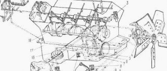
The boiler room is equipped with 4 cylinders forming a heat exchanger. It, in turn, has 2 cavities that help the exhaust gas circulate.
The outer part of the PZhD has 3 tubes necessary for the supply and removal of fuel, as well as for the exit of exhaust gas. Hitting the damped part of the boiler, the gas is directed to the outlet pipe. Thermal energy is spent on heating in the engine sump.
A pump that combines 3 pumps is considered a separate unit. It is this feature that distinguishes the device from other types of heaters.
For example, PZD 30 is equipped with a pumping apparatus. It can be installed not only above the boiler room. It can be placed anywhere, connected with hoses. Modification 15-8106 is mounted on the edge of the boiler, not far from the burner. In this case, the use of hoses is not required.