How the launcher works
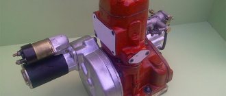
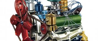
The PD 10 starting motor is designed to ensure stable starting of the engine of MTZ tractors; it stands out among other analogues with its excellent technical characteristics and high stability of operation. It is a standard launcher equipped with one cylinder. Its working volume is 0.346 liters, which is quite enough to start the engine even in unfavorable conditions. The power of the unit at 3.5 thousand revolutions reaches 10 hp.
Having studied the technical characteristics of the product, it should be noted that it is of a two-stroke type and is equipped with a crank-chamber purge. The engine runs on a gasoline mixture, the quality of which is regulated using a carburetor, which allows for finer tuning of the engine. The operating principle of such a device is extremely simple.
PD-10
First, the PD-10 is started through a standard tractor starter, after which it is connected to the main engine of the vehicle. With the help of mechanisms, rotational energy is transferred to the gearbox and, subsequently, the tractor crankshaft gains the necessary speed for stable independent operation. After the main engine has reached operating condition, the starting analogue stops operating.
Principle of operation
Before starting a cold engine, close the choke . In this case, the throttle valve opens under the action of the starting motor regulator spring. After stopping the engine for a long time, you need to press the drowner button .
- In this case, the diaphragm presses the lever, the valve opens, and fuel enters the chamber above the diaphragm.
- When the engine crankshaft rotates, a vacuum is created .
- Under the influence of vacuum, fuel flows through a spray nozzle .
- The fuel-air mixture is fed into the mixing chamber through the idle spray holes, and a re-enriched combustible mixture is formed .
- This creates conditions for reliable engine starting .
- Immediately after start-up, the combustible mixture becomes leaner , as the automatic valve on the air damper comes into operation.
- As the engine warms up, the air damper is opened .
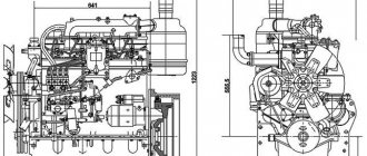
Diagram of the PD-10 starting motor
The starting motor of this brand consists of a number of components and appears to be a complex technical unit designed to ensure a stable start of the MTZ tractor engine. Studying its structure, the following key design elements can be identified:
- cylinder. Attached to the crankcase using nuts. Purge channels, strategically located tangentially to the circumference of the unit, reduce leakage of the mixture into the exhaust. The cylinder head is equipped with a spark plug;
- piston. Made from high-strength aluminum alloy. Its distinctive feature is a spherical bottom, which improves the quality of cleaning the cylinder from exhaust gas. If you want to achieve the correct position of the piston, you should place it so that the arrow on its bottom points towards the rear axle shaft of the crankshaft;
- connecting rod mechanism. Made of special grade steel, equipped with a bronze bushing. The mechanism heads are one-piece, and the bearing is double-row, roller type;
- gears;
- crankshaft. Roller bearings with rubber seals act as its support. In order to equalize the centrifugal force, the knees of the cheeks are equipped with special weights;
- The cooling system of the unit is connected to a similar system of the main motor.
Be sure to read: MTZ 82 brake design
These elements are key and take the most active part in the operation of this engine. At the same time, there are many other components, such as pins, rings, windows and other components.
Device
- The regulator shaft rotates on two ball bearings installed in the sockets of the front half of the crankcase. Between the bearings on the shaft there is a gear , which is driven into rotation by the intermediate gear.
- The drive disk of the regulator is screwed onto the thread of the middle part of the roller , in three grooves of which three steel balls . The balls in the grooves rotate together with the drive disk and move in the radial direction, moving away from the axis of rotation or approaching it.
- A movable disk is freely installed on the front smooth end of the regulator shaft . A bronze bushing is pressed into the disc hub, and a ball stop is installed at the end part.
- The movable disk with its conical part presses the regulator balls rotating with the drive disk to the support disk , which is pressed into the crankcase socket. The non-rotating parts of the regulator are mounted in an aluminum housing.
- An adjusting bolt is screwed into the upper horizontal threaded hole of the housing . A spring is put on the bolt, one end rests against the head of the bolt, and the other against the upper end of the internal double-arm lever.
- The lever is mounted on an axis, made as one piece with the outer lever, and secured to it with a pin. The lower end of the lever rests against the ball stop of the movable disk of the regulator.
- At one end of the outer arm there is a ball pin for articulated connection with the regulator rod coupling. The other end of the regulator rod is connected to the carburetor throttle lever.
PD-10 maintenance
As a rule, the launcher will not require much time from the owner to carry out maintenance work on the unit. It is important to remember that using fuel in its pure form, without first mixing it with oil, is strictly prohibited, as this can lead to engine damage and subsequent failure.
In order to refuel the engine, you will need to mix pure gasoline of proper quality and motor oil in a clean container, strictly observing the proportions of 15:1. When refueling, it is necessary to use a special filter funnel, which will prevent large and small contaminants from entering the internal components of the unit.
Scheme PD-10
As you use it, you should wash the fuel tank sump, and promptly wash or replace the air filter. It is recommended to do this every 480 hours of use. Since many problems that arise with the starter are associated with unsatisfactory cleanliness of the air filter, it should be periodically removed and cleaned, following the following instructions:
- Remove the air purifier protective cap and limiting mechanism.
- Remove the filter.
- Rinse it in diesel fuel, then moisten it with oil.
- Install the filter, restrictor mechanism and cap.
It is necessary to pay due attention to the maintenance of the gearbox operating in conjunction with the PD-10. First of all, the oil should be changed after 960 hours of operation, and topped up every 480 hours, as needed.
The functionality of the clutch assembly should be checked at similar intervals. During operation, it is necessary to remember that the operating time of the launcher should not be more than 10 minutes, otherwise the likelihood of its failure increases significantly.
Setup and adjustment
Its technical performance, as well as the stability and efficiency of operation, depend on the correct tuning of the engine, including the PD 10u. Adjustment of the device is carried out in several stages, the first of which is considered to be setting the carburetor.
Be sure to read: Vladimir Tractor Plant: official website, products
To do this, you should set the length of the rod between the damper and the regulator, and then adjust the engine operation at low speeds. After this, they begin to adjust the crankshaft, which can be done using the appropriate spring. The more it is compressed, the higher the engine speeds.
Then, you need to start setting up the ignition system, and the last, final stage will be setting up the mechanism responsible for turning off the drive gear.
Load mode
As the load on the starting engine increases, the throttle valve opens, the vacuum in the diffuser increases, and fuel enters the mixing chamber through a spray nozzle . As the throttle valve opens, more fuel is supplied to the mixing chamber.
The vacuum decreases at the idle holes when the throttle valve is opened. Therefore, fuel does not flow through these holes, but is distributed only through a spray nozzle .
As fuel is consumed from the chamber, the pressure above the diaphragm becomes lower than the atmospheric pressure below the diaphragm.
Under the influence of the pressure difference, the diaphragm bends upward , presses the lever and opens the valve. The upper chamber above the diaphragm is filled with fuel. The pressure above and below the diaphragm equalizes as the upper chamber fills, and the diaphragm moves down . The valve closes under the action of the spring, and the cycle repeats.
The transmission mechanism is mounted in housing 34 (Fig. 49), which is attached with three bolts to the flywheel housing flange. The body is closed by a cover 37, centered relative to the axis of the body by a guide belt that fits into the bore of the body.Shaft 14 rotates in two ball bearings 15 and 40 installed in the housing and cover of the mechanism. The longitudinal movement of the shaft is limited by the ball bearing 40.
On shaft 14, gear 12, pressed onto a bronze bushing 13, rotates freely. The longitudinal movement of the gear is limited on one side by a ring clamped between the end surface of the shaft and bearing 15, and on the other by the support disk 10 of the clutch of the transmission mechanism.
The drive drum 11 of the clutch is riveted to the gear with six rivets. The drive drum is stamped from sheet steel and has four protrusions that fit into the grooves of the three drive disks 8 of the clutch. Three driven disks 9 of the clutch are installed with four protrusions in the corresponding grooves of the cage 25 of the freewheel. The discs are made of 65G steel. The friction surfaces of the discs are polished. The driving and driven disks are located between the support disk 10 and the pressure disk 4.
The support disk 10 and the freewheel cage 25 are attached with four bolts to the freewheel hub 3, which sits freely on the shaft 14. The cage 25 is centered relative to the hub 3 by two alignment pins 7. A thrust bearing 5 is installed in the hub bore, through which axial force is transmitted ( when the clutch is engaged) to the shaft 14 of the mechanism and the mounting bearing 40 of the shaft.
Pressure disk 4 is centered on the outer surface of the cage 25 and is secured against rotation relative to the cage by two fingers 6 inserted into the grooves of the cage.
A spring 35 is installed between the pressure plate and the hub, which, when the clutch is disengaged, removes the pressure plate from the driven and driven disks.
The axial force required to compress the clutch discs and engage it is created by the release mechanism.
The shutdown mechanism consists of two bushings 38 and 39, mating along a screw surface, and a handle 1. The fixed thrust bushing 39 is pressed into the cover 37 and additionally secured in it with three pins.
At the end of the fixed thrust bushing there are two protrusions with a helical surface. The same protrusions are made on the movable thrust bushing 38, installed in the hole of the cover 37. A thrust bearing 36 is placed in the bore of the movable thrust bushing, through which axial force is transmitted to the pressure plate 4.
The toothed rim of the movable thrust bushing engages with a gear located on the handle rod 1. The handle rotates in the hole in the cover and is secured by screw 2 against axial movement. The gap between the handle rod 1 and the cover 37 is sealed with a rubber ring.
When the handle is turned toward you, the movable thrust sleeve rotates. When turning, it slides along the helical surface of the fixed thrust bushing 39 and, as a result, moves along the axis of the shaft. The movable sleeve moves the pressure plate through the thrust bearing, compressing the disks 8 and 9 of the clutch.
When the handle is turned in the opposite direction, the pressure plate, thrust bearing 36 and the movable sleeve are pressed towards the handle under the action of the spring 35.
The freewheel transmits torque in only one direction - from the starting engine to the main engine. In this case, a sharp increase in the speed of the starting engine is prevented when starting the main engine, when the engagement gear 31 has not yet disengaged from the flywheel ring.
The freewheel consists of a cage 25, four rollers 24, pushers 23 and springs 22.
The cage has four grooves, the cylindrical surface of which tapers in the direction opposite to the rotation of the mechanism shaft.
Rollers are placed in the grooves. They are pressed by pushers under the action of springs in the direction of the narrowed part. When the cage rotates counterclockwise, the rollers, under the influence of friction, roll into the narrow part of the groove, jam the cage 25 with the shaft and rotate it. If the shaft rotates counterclockwise faster than the holder, the rollers will come out of the narrowed part of the groove, overcoming the force of the springs, and separate the holder from the shaft. In this case, the connection between the holder and the shaft will be broken, the rollers will roll along the shaft. The clutch in this case works almost the same as a regular roller bearing.
The transmission shutdown mechanism is designed to engage the gear 31 with the flywheel ring gear of the main engine and automatically turn off the gear after it starts.
Gear 31 with an automatic shutdown mechanism is installed on the splined end of shaft 14. It moves freely on the splines along the shaft. The longitudinal movement of the gear is limited on one side by the oil seal sleeve 17 and on the other by the pusher sleeve 28, screwed into the threaded hole of the shaft end. A holder 29 weights of the automatic shutdown mechanism is placed on the gear hub and attached to it with six bolts secured with wire. In the grooves of the holder, on the axes 26 installed in its eyes, two weights 27 swing freely. In them, under the influence of the force of springs 32 and 33 located in the shaft hole, the pusher 30 rests. It strives to disengage the engagement gear with the holder from the flywheel ring. , i.e. move it to the rearmost position.
Gear 31 is brought into engagement with the flywheel ring using handle 18 installed in the clutch cover of the main engine. When the mechanism is turned on, lever 19, pressing on the end of the holder, moves it together with the gear forward, towards the transmission mechanism, and engages the gear with the flywheel ring. In the on position, the gear is fixed by weights, which, when moving the holder, with their ledges extend beyond the head of the pusher guide bushing and are held in this position under the action of springs 32 and 33.
The gear disengages from the flywheel ring automatically when the shaft speed increases so much that the resulting centrifugal forces of the loads overcome the force of the springs, and the loads diverge.
The starting motor transmission mechanism works as follows. Before turning on the starting engine, the engagement gear 31 is engaged with the flywheel crown, moving the handle 18 forward to full stop. In this case, the weights of the automatic shutdown mechanism with ledges grip the head of the guide sleeve and hold the gear in mesh. Then the handle 18 is retracted to its original (rear) position. The clutch of the transmission mechanism must be disengaged when starting.
When the starting engine is running, the crankshaft gear transmits rotation through the intermediate gear to gear 12 of the transmission mechanism. Together with gear 12, the drive disks of the clutch rotate. After starting the starting engine, the clutch is smoothly engaged. When the clutch is engaged, rotation is transmitted through the cage 25, rollers, mechanism shaft, gear 31 and the flywheel crown to the crankshaft of the main engine.
At 3500 rpm of the starting engine, the main engine crankshaft rotates at a starting speed of 210 rpm. During the start of the main engine, as a result of possible individual flashes in the cylinders, the crankshaft speed may increase, and at the same time the speed of the transmission mechanism shaft will increase. At the same time, the freewheel is automatically turned off, protecting the starting engine from increasing speed.
When the main engine is started and its speed begins to increase, the number of revolutions of the mechanism shaft will increase. When the engine reaches 460-600 revolutions per minute, the weights disengage with the pusher guide sleeve and the gear with the holder disengages with the flywheel ring under the action of springs 32 and 33.
To lubricate the transmission mechanism, there is a filler hole in the starting motor housing, closed by plug 36 (see Fig. 41). The level of oil being poured is determined by the control hole into which plug 20 is screwed (Fig. 49). There is a drain hole in the lower part of the housing to remove used oil, which is closed with plug 21.