Service frequency
The two-cylinder diesel engine D-21 installed on the tractor has an air cooling system.
This power unit is unpretentious and, during normal operation, does not require frequent intervention in the operation of the gas distribution mechanism.
Unlike heavy modifications, such as the T-40 or T-100 tractor, the T-25 tractor has to be serviced more often.
According to the operating instructions, the valves of the T-25 tractor are checked and adjusted every 240 operating hours.
If adjustment is required more often, this indicates a malfunction. Among the most common malfunctions:
Before you begin adjustment work, you will first have to replace the damaged parts.
Otherwise, even if the adjustment is done correctly, you will only waste your time and energy.
Adjusting the valves of the MTZ tractor
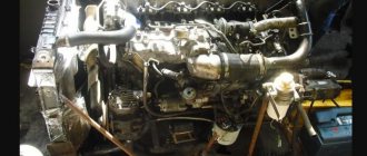
The procedure for adjusting the valves of the MTZ tractor and the sequence of setting up the machine systems depend on the engine modification and the principle of air supply to the combustion chamber. The regulations involve checking and adjusting the gap between the rocker arm striker and the end of the air intake and exhaust valves into the exhaust manifold. Be sure to check the tightening force of the nuts securing the head to the cylinder block in order to reduce the risk of gasket breakdown and deformation of parts under thermal loads.
At the preparatory stage the following is performed:
- removing the sides and opening the hood;
- loosening the fastening nuts;
- dismantling the gas distribution mechanism casing on the diesel head;
- cleaning the surfaces of parts from carbon deposits, oil and dust;
- checking the tightening force of the bolts on the roller holding the rocker arms.
Next comes the direct adjustment work. First, set the cylinder piston to the top dead center of the compression stroke. To do this, begin to manually turn the crankshaft using a wrench until the intake valve opens. On an early modification of the D-240 engine with a mechanical fuel pump, it is permissible to unscrew the injector. To determine the upper position of the piston, use a pin lowered into the hole. The piston can be installed at TDC by removing the fuel supply pipe. However, accuracy is not guaranteed, since fuel injection starts early.
If valve adjustment is necessary for MTZ 50/52 or YuMZ-6 tractors powered by a D-50 engine, then you can set the upper position of the first piston as accurately as possible. A through hole with a thread is made in the flywheel housing of the power plant for screwing in the mounting pin. It has a section with a rounded head that fits precisely into a recess in the body of the flywheel.
To set the thermal clearance of the intake and exhaust, first unscrew the nut that secures the valve rocker arm adjusting screw from turning. Then use a screwdriver to unscrew the screw until the gap is 0.25 mm for both positions. After this, the nut is placed in its original position.
If it is necessary to carry out adjustments on the D-50L motor, on which a decompressor valve driven by a separate roller is installed, then the screws are placed in a vertical position, and then the lock nut is released and the screw is unscrewed using a screwdriver to the position of the spherical head and the surface of the roller. After this, the screw is tightened until it stops, and before tightening the fixing nut, it is turned another 0.8 turns to avoid disruption of the clearances during operation, which can lead to contact between the decompressor elements and the piston.
Dangerous Misconception
Do not attempt to perform work using the service instructions of other equipment. This will cause serious damage.
In terms of design, the gas distribution mechanism on the T-25 tractor has much in common with similar systems of other machines that have engines with a lower camshaft.
The schematic diagram of the D-21 engine will allow you to see this in more detail. Adjustment of the T-40 valves is performed differently, since, unlike the D-21 engine, the D-144 engine has four cylinders and different valve timing.
Note | Special equipment
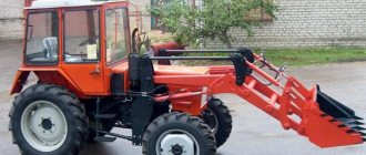
In Russia, the demand for farming equipment is constantly growing. This is due to economic problems in the country. But domestic industry, as it turned out, is not capable of producing equipment for small farms. Therefore, this entire niche has almost been completely occupied by China, which sells it here under a variety of Russian brands. This is exactly the case with mini tractors. Among them, the only Belarusian tractor, Belarus-132N, stands out, which is completely, with the exception of the engine, made in Belarus.
Brief characteristics
Unfortunately, this tractor does not use a diesel engine, which is used on Chinese equipment for similar purposes, but a 4-stroke gasoline engine. Manufacturers abandoned their own engines due to low reliability and increased vibration levels.
After experiments with an American 2-cylinder engine from the B&S company, a 1-cylinder Chinese engine from the Lifan company and a Japanese engine from the Honda company, manufacturers settled mainly on the Japanese Honda GX390 engines, as the most reliable and durable. However, a gasoline engine is less fuel efficient than a diesel engine in terms of fuel consumption.
Its consumption is 0.313 kg/kW per hour, and its power, at a nominal 3600 rpm, is 9.6 kW, or 13 hp. c. The minitractor's transmission is purely mechanical, multi-disc oil clutch, 7-speed gearbox, 3 of which are reverse speeds.
Belarus-132N is made according to a 4x4 wheel arrangement, and the front axle differential has the possibility of semi-automatic mechanical locking, which significantly increases traction force if necessary. The locking is controlled using a lever on the dashboard. The rear axle is switchable. The tire size for all wheels is the same and can be either 6.0x12” or 5.9x13, depending on the product modification.
To improve the grip of the wheels on the ground, the minitractor is equipped with rear and front wheel weights of 17 kg each. Its total weight with ballast is 532 kg. Dimensions – 250x100x200 cm with canopy installed. Longitudinal base - 103 cm, ground clearance - 27 cm. The track width is variable and can be 84, 70 and 60 cm. Traction force - 2 kN, or about 196 kg.
The main difference between the Belarusian mini-tractor and Chinese cars is that its frame, on which the entire structure is assembled, is articulated, like heavy tractors such as the Kirovets. This design provides maneuverability, high maneuverability in hard-to-reach places and a fairly small turning radius of 2.5 m.
Anyone who saw how the Belarus-132N moves across the field, especially at high speed, could notice that its movement is strikingly different from the movement of any other mini tractors. It seems that when it moves, it wriggles like a worm or a face. And in fact, since its chassis is hinged, its entire structure bends when turning, and visually its maneuverability is simply amazing.
And all this mechanism is controlled by an ordinary steering mechanism based on a worm gear, even without hydraulic boosters.
The trailed and hydraulic mounted system of the Belarus-132N minitractor is also more developed than that of Chinese equipment. The hydraulic attachment is designed as a four-link hinge with adjustable length braces. With a suspension length of 305 mm, its load capacity is at least 1.4 kN (about 137 kg). A towing device of a combined type in the form of a crossbar installed at the ends of the longitudinal rods.
Sequence of operations
The T-25 Vladimirets valves are adjusted in the following sequence:
To avoid mistakes and make sure there are no breakdowns in the gas distribution system, repeat the adjustment cycle again.
If the gaps change, adjust again. If after this the problem is not resolved, look for a breakdown.
With proper maintenance, the T-25 tractor will work for a long time, demonstrating enviable reliability and efficiency.
Adjusting valves on the T-40 tractor
The gas distribution mechanism of the T-40 tractor requires scheduled valve adjustment. At the same time, monitor the level of lubrication of the camshaft elements and the degree of their fit. Maintenance of the T-40 tractor is carried out every 480 hours of operation.
The clearances on this model are set only when the engine is cooled. First, unscrew the locknut holding the screw on the rocker arm, and then use a wrench to tighten the screw itself to set the required clearances. To check the parameters, use a probe. At the final stage, tighten the locknut and take control measurements.
Next, move on to the stages of the main work:
- move the crankshaft to the side;
- align the marks at TDC and the ventilation system of the device of the first cylinder and tighten both valves;
- loosen the locknut and select the optimal clearance level;
- screw the locknut all the way in and measure the gap using a push rod;
- change the position of the crankshaft and move on to adjusting other valves.
If the adjustment is carried out on a warm engine, then temperature deformation can distort the clearance parameters, causing the adjustment to be inaccurate.
Device, spare parts and components.
SPARE PARTS FOR TRACTORS
ADJUSTMENTS OF MTZ TRACTORS ___________________
DIESEL ENGINE PARTS ___________________
MTZ SPARE PARTS CATALOG ___________________
TECHNICAL CHARACTERISTICS OF TRACTORS ___________________
SPECIAL EQUIPMENT BASED ON MTZ AND ATTACHMENTS ___________________
AGRICULTURAL MACHINERY AND EQUIPMENT ___________________
Gearbox and clutch repair
The T-25 tractor gearbox does not have synchronizers, but has a doubler and reverse. There are 8 gears for forward movement and 6 reverse gears. The gearbox itself, the differential and the main gear are located in one housing, which will facilitate access to these components for repairs. Partial disassembly is possible even without removing it from the tractor.
Possible problems
- The bushing and bearing seats can quickly wear out or become damaged, which ultimately leads to a complete replacement of the crankcase casting. Try to monitor the condition of the bearings and change them on time.
- Periodic adjustment of the installation gaps of shafts, bearings and gears is required. Doing this job requires some skill and tons of patience. But when everything is adjusted, the gears shift easily and clearly, which guarantees a long service life of the box.
Parts that need to be constantly monitored in the T-25 gearbox, because... they most often fail.
- moving gears,
- bearings,
- clamps and rollers,
- gear forks,
- secondary shaft stops,
- ears of the lock washer and the retainer cover.
Under no circumstances should you pour modern synthetic gear oils with high viscosity into the gearbox. Remember that the T-25 tractor itself was developed in the middle of the last century, and lubricants then were of a completely different quality. We recommend using mineral gear oil W90 standard GL3.
Disassembling the gearbox
- Open the transmission housing and remove the bearing cover on the left, where the main shaft is located.
- Remove the power take-off shaft cover.
- To remove the cup with bearings, unscrew the clamping nut and bushing.
- To remove the reverse, remove the lock washer on the left and turn it 30 degrees. And remove the stopper from the bearing.
- Assembly is performed strictly in reverse order. When repairing the gearbox, inspect all parts that are heavily worn and replace them with new or reconditioned ones.
Clutch maintenance and repair
The clutch on the T-25 is a dry, single-plate, permanently closed clutch. In some cases, clutch slippage may occur due to improper clutch adjustment or due to oiling of the disc. Oil can get onto the disk from the hydraulic pump or from the engine through the oil seals and seals of their drives. To remove the oil, the clutch is disassembled, the driven disc is pulled out, washed in gasoline and dried.
To adjust the clutch, place the gearshift lever in neutral and remove the connecting housing cover on the left side. Turn the crankshaft with a wrench so that three clutch release levers alternately appear in the hatch. Using special plates, check the gaps between the thrust bearing and the end of each lever; it should be 2-3 mm. The difference between individual levers should not exceed 0.1 mm.
If the gap does not meet the required values, unscrew the lock nut and turn the adjusting bolt until you obtain the desired gap. After this, do not forget to tighten the locknut onto the bolt. As the friction linings wear, the gap will gradually decrease. If it decreases significantly, then when the clutch is engaged, the bearing will constantly rotate, quickly wearing out itself and the levers.
If the clutch driven disc is worn to the point that the rivet heads are visible, then the worn linings are replaced.
Lubrication of the front bearing of the clutch shaft and the lift housing is carried out only during complete disassembly of the tractor.
During operation of the tractor, oil will inevitably leak through the seals. To release it, it is recommended to periodically turn the cotter pin at the bottom of the connecting body.
Adjusting the injection pump
In order to adjust the speed of a diesel engine on a T-25, you need to change the spring tension. This is done using a screw that is screwed into the control lever. To increase the speed, the screw is screwed in, increasing the stiffness of the spring and reducing the number of its working turns; to decrease it, the screw is turned out, reducing the stiffness and increasing the number of turns.
Adjustment procedure
- The injection pump is installed on a stand and the fuel line is connected to it. Starting fuel supply is set at 50-100%
- Unscrew the screw from the control lever completely, set the lever itself to the maximum speed position and screw the screw back until it stops.
- By moving the housing relative to the cover, you need to set the fuel supply at the nominal camshaft speed.
- Set the starting value of the regulator at 10-15 rpm. Cam shaft.
- Check the fuel supply at nominal mode.
- Check that the fuel supply is completely shut off through the injectors.
- Adjust the camshaft speed.
- Using the screw, adjust the fuel supply so that there is sufficient reserve of engine torque for normal operation.
T-25 tractor repair Questions and answers
This article contains questions and answers from people who encountered problems when repairing the T-25 tractor.
How to reduce play on the steering column of the T25 tractor?
On the right side of the hydraulic distributor at the bottom of the steering wheel there is a nut, unscrew it, there is an adjusting screw usually for a screwdriver, so we turn it clockwise, to eliminate the play you need to move the worm closer to the shaft, also look at the bipod shaft bushing, if there is play, change the bushing , check the front axle balancer, there is movement, change the bushing. We check the steering rods, there is play, we change the end bearings, use the adjusting bolt to move the roller relative to the worm to the right or left, tighten the adjusting bolt with a nut, the result is positive, if not, the steering rod fingers are broken.
Final drive crunching?
The final drive has roller bearings. If they are crushed, the wheel may fall off along with the axle shaft and even break the axle shaft. This usually happens on a wide track, set the track to 1400mm, the problem disappears.
We adjust the reverse so that it does not hum.
The reverse is adjusted using repair washers (thin plaques). When the reverse is assembled, take a sheet of newspaper and insert it between the gear teeth. When turning the reverse, the gear teeth should not cut the newspaper.
We are installing an additional hydraulic tank, are additional modifications required?
There are no improvements. We drain the additional tank into the filler neck of the original tank, and that’s all the modifications. We drill the filler plug, insert the fitting onto the thread, and put on the hose.
Will there be pressure on the oil filter?
There will be no pressure on the filter, there will be a hose with additional. tank in the original tank in the filler neck, the excess will be drained into the additional tank. tank through this hose.
We knock out the steering knuckle bushings.
We place the beam on a rigid stand, take an extension, preferably one that goes inside the body of the beam. We take a good hammer and knock out the bushing with strong and sharp blows. It is important that the beam does not vibrate, if it does not move, soak a rag in kerosene and place it on top for a day, knock it out, if that doesn’t help, heat it with a blowtorch and knock it out carefully, but firmly so as not to flare the edges of the beam.
Piston for PD-8 launcher.
The piston from Izh Planet fits on the PD10, on the PD8 it fits from the Tula scooter, it’s better from a truck, the piston has 3 compression rings and it will be better to start. There is a piston on the “ant”, with PD 8, since sunrise the piston will not fit a finger smaller in diameter
Power steering for T-25.
I installed a pulley from a T-40 and the tractor began to tremble, it turned out that the pulley was not balanced. I connected from the pump to the dispenser, the return to the distributor works not bad, but there is one thing. When lifting the hitch, it sometimes throws to the left. And so everything is fine with one finger.
Install a T16 steering wheel and don’t worry. I used to suffer too. then he spat and remade it.
I rebuilt the steering from T16, installed an NSh 10 pump, placed it above the generator, driven by a belt drive.
We change brake bands.
Disassemble one part of the tape that you will be changing completely, flatten the ear a little, hook it with a thin cable, and run the cable under the drum. The wheel is jacked up, pull the cable and spin the wheel. After removal, make sure the tape is dry. If the band is oily, replace the seals immediately, otherwise even new brake bands will work very poorly.
My brother changed it, removed the top cover, pulled the tape with a wire and pulled it out with a crowbar. Then he wound the wire under the drum, inserted the tape as far as he could, and, pulling the wire, inserted the tape into place.
We change the rear tires to wide ones.
We are replacing the power steering pump.
I installed a three-section distributor on my tractor; one section is not fully engaged, it only works in two positions, lowering and floating, and it’s very convenient for me with my hand on the lever, down, lift, floating, and up neutral. There is probably only one option for NSh 32; it probably needs to be installed only forward on the crankshaft, through the cardan. You can go to the same place where the original one is, only the gearbox needs to be changed, and there is no place to put it in front. I have an NSh-10 on the front end with a belt drive. With T16, the steering column was installed with a hydraulic steering much simpler.
The wheel lock is stuck.
The box is removed in one block with the rear axle, if desired, the whole box can be disassembled on site, and I also had a tractor with a homemade cabin, so I don’t know if the floor of the cabin is completely removed, can you remove the cover without removing the cabin and crawl up to blocking?
We remove the cabin assembly, remove the box cover, but here you will have to tinker with the brake shafts, they will not allow you to remove the cover. If the shafts have not been removed, this may not be so easy. If the clutch is stuck, you may have to disassemble the entire left final drive. If you remove the cover, cut it with a grinder in the area of the clutch shaft; in the future, when repairing the box, you do not need to remove the cabin.
What about the brake shafts? what to do if they have never sorted it out?
The shafts in the cover are locked with pins; sometimes the pins are very difficult to pull out. They are small and sometimes they fit tightly, depending on how it goes. And if you drove a tractor with the locking switched on, could the gears be cut? If the gear is not cut, it often breaks off the bolts that secure the gear to the cup. If the bolts are loosened, a dull knock appears when starting off, regardless of whether the lock is engaged or not. Even if you have a problem with the load release mechanism, the clutch would be thrown out anyway. It happens that under load you hold it with your foot and feel how the clutch is knocked out, apparently, the clutch and gear are bitten and, moreover, tightly
How can I disengage it after I open the box?
In this case, opening the box will not help; you will need to completely remove the left side. If the problem is in the locking gear, it will be necessary to remove the differential, and for this it is necessary to remove the right side one. In general, replacement requires complete disassembly of the main gear. I've had similar repairs. There was a case where the unusable locking gear was completely cut off, and the tractor was operated without any locking at all; in another case, a differential was installed with dt 20, which is not there from the factory. Tractors still operate without blocking.
What could be wrong with the fuel pump, they replaced my high pressure section, now the engine starts with difficulty and the exhaust has become loud?
I suffered for almost a month. Then I found the reason, it turned out that I had installed a new high-pressure tube, and it was defective and did not allow all the diesel to pass through.
d-21 “reducing valve” what role does it perform? Is the valve adjustable?
It regulates the pressure in the engine, you can adjust the desired pressure. What pressure should be in the engine? How is it regulated? On cold 4, on hot 3, wrap it a little and try. Adjust when cold or warm? Doesn't matter.
The valve limits the maximum pressure of a cold engine. Adjustable at cold 3.5. If a normal engine at 80 degrees will hold 3. If not, then even 4 when cold will not help.
Which flywheel is suitable for the T-25 engine? Non-standard assembly. Engine D-21, basket, release, gas box 52.
I want to attach a gas 52 basket and a box to d-21. Welded bell from a wheel disc or pipe. I can’t find it for the D21 engine. They say they are different.
For my T-40 engine, a large circle is cut out onto the block; it is cut out from a Kirov part; it is somewhere in the gap near the tractor, and a bell from GAZ-53 is screwed onto this circle; the rest is a clutch from GAZ-52 and a gearbox from GAZ-52 Flywheel It is not advisable to depersonalize the crankshaft during repairs; there is no guarantee of balancing. But ideally, the D-21 flywheel is bored out so that the GAZ-52 basket fits in, and secured. The GAZ-52 basket is technically not very interesting.
I don't like the basket because of the suspension of the legs and their adjustment. I plan to insert the GAZ-53 disk into the bored hole, the pressure disk of the GAZ-53 basket will fit, I will cut off the basket casing, insert it into the hole on top of the basket, and weld plates to attach it to the top of the hole. Or I will fit the T-25 clutch into the bored hole of the flywheel onto the GAZ-53 disc.