Operating principle of the PD-10 carburetor
Before starting work (that is, before turning on the engine), it is necessary to close the damper, at the same time, under the action of the control spring, another damper, the throttle, closes. After stopping the engine for a long time, you will need to pull the drowner lever. The diaphragm acts on the lever, the valve opens, and with it the passage for fuel into the chamber.
The fuel is discharged by rotation of the crankshaft, after which it enters the mixing chamber. It mixes fuel with air, resulting in a mixture that is over-enriched with oxygen. All these processes ensure immediate starting of the carburetor and engine.
After starting, the fuel loses a significant proportion of oxygen; this simple job is performed by an automated air damper valve. Gradually this valve opens wider and wider.
Adjustments in the ignition system of starting engines
In the ignition system of starting engines, the following are regulated: the gaps between the spark plug electrodes and in the breaker contacts, as well as the ignition timing.
There should be a gap of 0.6-0.7 mm between the central 1 (Fig. 36) and side 2 electrodes of the spark plug It represents a certain resistance to the electrical discharge of current to produce an intense and stable spark capable of igniting the slave mixture in the combustion chamber. A small gap worsens the discharge, makes it difficult to start the engine, causes interruptions in engine operation, and sometimes it stops. An increased gap leads to an increase in breakdown voltage and a decrease in the reliability of the electrical circuit.
During engine operation, this gap changes due to burning of the electrodes, carbon formation on them and corrosion.
The gap is measured with a probe inserted into the gap between the electrodes, cleaned of carbon deposits. It is restored by lightly tapping the side electrode (to decrease it) or bending the side electrode (to increase it).
Adjusting the gap (0.25-0.35 mm) between the breaker contacts in the open state establishes a certain ratio between the periods of the closed and open state of the primary magneto circuit. This ratio has an important influence on the conversion of low voltage current and the formation of an intense electrical discharge.
During operation, the gap changes due to burning and corrosion of the contacts, so it is necessary to systematically check the condition of the contacts and adjust the gap after cleaning. To adjust the gap, the breaker has an eccentric screw 8 (Fig. 37). To increase the gap, you must first loosen screw 6 by 1-1.5 turns, securing the stand 5 with fixed contact 4 (anvil), and then turn screw 8 with a screwdriver to obtain the required gap between the contacts. During adjustment, the gap is checked with a feeler gauge. Having established the required gap, screw 6 is tightened.
Simultaneously with adjusting the magneto, it is recommended to check the elasticity of spring 2 of the hammer with a spring dynamometer with a scale of 1-1.5 kg. Hooking the moving part of the dynamometer onto hammer 3, tighten the dynamometer until a gap of 0.25-0.35 mm is obtained. The instrument indicator should be at the level of 500-800 g. The weakened spring is replaced with a new one.
A magneto combines an alternator and a step-up autotransformer with a breaker in the primary circuit. A spark discharge in a spark plug occurs when a breaker breaks the primary circuit and maximum electromotive force is induced in it. This moment corresponds to a certain position of rotor 1 (Fig. 38) of the magneto, when it is rotated at an angle of 8-10° in the direction of rotation from the position of the closed poles. The angle corresponding to the position of the rotor poles at the moment the breaker contacts begin to open is called the magneto outline; for a new magneto, the outline is set by combining the marks applied (during manufacture) on the cam and on the breaker disk. If the magneto part is dismantled, it is necessary to reinstall the outline and apply new marks.
To install the outline, loosen the screws securing the breaker disk to the body in order to move the disk around cams 7 (Fig. 37) and put the rotor in the closed pole position. Then turn the rotor in the direction of rotation by 8-10° and, by shifting the breaker disk, find the position where the breaker contacts begin to open. In this position, the disk is secured with screws and new combined marks are applied on the disk and on the cam. Old risks are forgotten.
After setting the outline of the magneto and finding the moment when the contacts begin to open, it is necessary to carefully check the magneto in operation.
The following setup techniques are recommended.
- To shift the rotor by 8-10° from the position of the closed poles, without resorting to special measuring tools, it is enough to set a gap of 2 mm between the upper inner edge of the pole of the rack 2 and the edge of the rotor, turning the rotor in the direction of rotation. This gap is controlled with a feeler gauge, which is inserted between the edges and the rotor is held in this position while finding the moment when the breaker contacts begin to open.
- The moment when the breaker contacts begin to open is determined using a strip of tissue paper sandwiched between the contacts. By shifting the disk relative to the stationary cams, the moment is determined when the hammer begins to run into the cam and the contacts open (the paper is easily pulled out). At this moment the disk is stopped and secured. A more accurate way is using a light bulb. If you connect a battery, an electric light bulb and an adjustable magneto breaker in series, then the light bulb will shine when the contacts are closed. By shifting the disk relative to the stationary cams*, the moment when the light goes out is determined; this corresponds to the moment the contacts begin to open.
When installing a magneto on the engine, check and adjust the ignition timing . The installation process is divided into three stages: engine preparation, magneto preparation, magneto and engine connection.
Engine preparation consists of installing the piston (the first cylinder for the P-46 engine) during the compression stroke to a position where the crankshaft does not reach c. m.t. at a constant ignition timing angle. For the PD-10 engine this angle is 37-39°, and for the P-46 engine it is 24-27° when equipped with an M-10A magneto and 6-8° when equipped with an M-47B magneto. To put the crankshaft in this position, for a four-stroke P-46 engine it is necessary to place the piston of the first cylinder in the compression stroke position when both cylinder valves are closed, and align the “ignition” mark on the flywheel with the mark on the engine crankcase. For a two-stroke PD-10 engine, this piston position is obtained by combining the “M” marks on the magneto drive gear and on the intermediate gear.
Preparing the magneto comes down to installing its rotor in a position that corresponds to the moment the breaker contacts begin to open. The moment of opening is determined using tissue paper or a light bulb. For a two-cylinder P-46 engine, it is also taken into account that at this moment the magneto distributor must supply current to the high voltage wire for the first cylinder. If, at the obtained moment of starting to open the contacts, the distributor is not located opposite the desired contact, the rotor must be turned in the direction of rotation to another position of the distributor and again find this moment.
The magneto and engine can be connected only after the preparation stages. The magneto drive device is connected to the engine shaft, the magneto housing is secured to the engine, and the high voltage wires are connected to the central electrode of the spark plug. The M-10A magneto uses only two wires, designated 1 and 2. The remaining wires are connected to the spark plug of the starting air heater, if the engine has one.
If interruptions in engine operation or detonation are noticed, check that the magneto is installed correctly. Remove the wire from the spark plug (the first cylinder of the P-46 engine), bring its end to the engine block or to the magneto housing with a gap of 5-7 mm and slowly turn the engine crankshaft. The M-10A magneto has a starting accelerator, so the moment of spark discharge occurs in position B. m.t. of the piston or a few degrees later. For magnetos of other types that do not have a starting accelerator, correct installation is characterized by the correspondence of the moment when the breaker contacts begin to open with the coincidence of the marks on the flywheel and on the block. If there are no such marks, then the position of the piston at a given ignition timing angle is # set as follows. Disconnect the wire and unscrew the spark plug. The rod is inserted into the vacated hole until it stops at the bottom of the piston. Turning the crankshaft, find c. m.t. of the piston by moving the rod. Then the shaft is turned in the opposite direction until the rod drops 5-6 mm from position c. m.t. This is how the piston of the PD-10M engine is set to an ignition timing angle of 27°.
If the installation is inaccurate, the advance angle is corrected by rotating the magneto housing relative to the rotor shaft, having previously loosened the bolts securing the housing to the block for this purpose. The adjustment must be combined with checking the advance angle. At the end of the work, the housing mounting bolts are tightened.
Carburetor operation under high loads
There are often cases in which the mechanisms experience excessive loads. So what happens in such situations in the carburetor itself?
The starting motor takes the hit first. The throttle valve opens, the degree of vacuum increases in all compartments, and fuel enters the mixing chamber. Since complex work needs to be done, more fuel enters the combustion chamber than usual. The liquid begins to discharge at the idle openings themselves, at the moment the damper opens.
Over time, the volume of fuel located in the tank cavity decreases, and the diaphragm pressure decreases. And the pressure under the diaphragm undergoes only minor changes.
A pressure difference arises, the diaphragm touches the lever, and the valve opens. The upper chamber is filled with a new batch of fuel. When there is not enough space in the tank, the pressure in both parts returns to normal and the hole closes again. This cycle can be repeated endlessly.
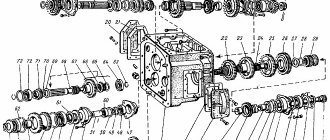
Device
- frame
- air and throttle valve
- fuel valve mechanism
- diaphragm
- lid
- main dosing system
- idle system.
The main dosing system includes:
- diffuser B, made in the form of a narrowing body,
- plate valve
- spray jet.
Idle system:
- fuel jet D idle
- channels B and D idle
- outlets A
- air jet
- mixture adjustment screw
- lever and stop screw on the throttle axis.
The diaphragm with the body and cover forms two chambers: the upper one above the diaphragm and the lower one below the diaphragm.
The upper chamber communicates with the fuel tank through the valve using a valve, and the spray nozzle and outlet openings A communicate with the carburetor mixing chamber.
The lower chamber is connected to the atmosphere through a balancing hole. The lever holds the valve closed with a spring.
Figure 1. a - general view (top); b - operation diagram (bottom figure);
1 - body; 2 — throttle valve; 3—thrust screw; 4 — screw for regulating the mixture composition; 5 - automatic valve; 6 — air damper; 7 — air jet; 8 — nozzle-spray; 9 - diaphragm; 10 — drowner button; 11 - spring; 12 — lever; 13 — housing cover; 14 and 15 - valves.
Carburetor adjustments
Adjustment is made using several screws:
- Qualitative . Changes the concentration of various substances in the fuel.
- Quantitative . Regulates the amount of mixture by weight and volume. Thanks to these indicators, the engine speed changes.
- Toxic . Increases or decreases the proportion of oxygen in the fuel-air mixture.
In different variations of the carburetor, other additional screws may be present. But they all change how the engine operates at idle. It is worth remembering that idle speed itself is very unstable, which is why all these adjustment tools exist.
Adjusting the carburetor of the starter MTZ 80
If you need to adjust the MTZ 80 launcher, I recommend that you watch this video, here is an excellent starting manual carried out by professionals.
Setting the carburetor to 16 for the starting engine
If you have installed a 16 carburetor on your starting engine and need to adjust it, I recommend watching this video.
General information
Modern diesel engines are started either by a starting engine (started by an electric starter or manually using a cord), or directly by an electric starter.
In the first type of starting system there are adjustments to the power system, ignition, etc. of the starting engine, the mechanism for engaging the gear of its drive, as well as adjustments to the control mechanisms of the starting system.
The second type of starting system provides for adjustments to the starter and starting device control mechanisms. Laser and photodiode modules of Lazerskoe LLC can be purchased on the website www.kvbel.com.
Features of using this type of carburetor
The operation of this engine has a number of minor differences from its “relative”. But still, taking them into account, you can make the mechanisms easier to use and minimize the likelihood of breakdown.
- Firstly, the driver completely controls the operation of the engine; PD 10 does not have an electronic unit that can regulate and configure the operation of the carburetor without the influence of the car owner.
- Secondly, not in all cases it is possible to sharply increase speed and gain power.
- And finally, thirdly, every 38,000-40,000 km. After kilometers traveled, it is advisable to disassemble and clean the carburetor.
Repair and maintenance
To maintain tractor equipment of this type in constant working condition, it is necessary to assess the weather and climatic conditions of using the tractor and, in accordance with them, carry out regular technical inspection.
Of course, the owner can carry out almost any repair himself, but it is better to entrust all repair and maintenance work to specialists.
Maintenance of MTZ-80, 82 tractors and its modifications takes place according to a special numbering system, where regulated time intervals for passing ETO (monthly technical inspection) are established.
- Every 60 operating hours.
- Every 240 operating hours.
- Every 960 operating hours.
Naturally, if problems and malfunctions are detected during work, unscheduled work can and should be carried out in circumvention of the regulations.
Also, when operating the starting and main engines MTZ-80, 82, it is necessary to take into account seasonal changes and transitions from the spring-summer to autumn-winter period.