Adjusting the Fuel Pump MTZ-1221
Due to the fact that the demand for high-pressure fuel pumps of group 32 produced by the Noginsk Fuel Equipment Plant is not high, and the Minsk Motor Plant does not supply them on its D engines, NZTA has temporarily suspended their production. In case of poor fuel atomization, clean the nozzle from carbon deposits by disassembling the nozzle.
The fuel enters through the fitting to the filter, filling the space in the form of a ring in the housing, and then, through the holes of the distributor, it is supplied to the inner space of the glass. To replace the filter element you must: Close the fuel tank tap. With the help of a spring, the main purpose of which is to transfer pressure to the rod, the spray needle is pulled close to the conical base of the spray. Next, the fuel is supplied to the fuel pump, which drives fuel under high pressure into the injectors. A change in the thickness of the washer by 0.1 mm corresponds to the angle of rotation of the cam shaft. Install the high pressure pipes without disconnecting them from the injectors. Secure the adjusting screw by tightening the lock nut and screw the cap onto the nozzle. There are two types of fuel purifiers on MTZ tractors: a coarse filter. The components of a coarse filter include the following elements: a housing and a damper, a glass with a filter element, and a distributor. Pour ml of engine oil through the plug on the regulator cap and start the engine. In this situation, the main cause may be a number of reasons: oil entering directly into the fuel combustion chamber, which can be caused by either its excess in the oil pan or wear of the piston system, incomplete combustion of fuel, problems with the initial supply of diesel fuel in the pump. MTZ 1221 Installation of fuel injection pump
Algorithm for setting the angle
Wash the inner cavity of the filter and the lid. Slowly press the lever on the stand and watching the arrow of the pressure gauge, determine the beginning of the rise of the MTZ injector needle. The engine has a sectioner. Slowly pressing the stand lever and observing the pressure gauge arrow, determine the pressure at which the MTZ injector needle begins to rise
Real fuel consumption is calculated based on observations of the unit. Cleaning the coarse fuel filter of the MTZ Belarus engine Wash the coarse fuel filter by performing the following operations: – Turn off the fuel tank tap. Replace the fluoroplastic gasket with the screen gasket. In these clips you can more or less gauge the reaction of people to this or that law, or to the situation in the country or the world. After warming up the diesel engine, re-tighten the injector mounting bolts to a torque. Before installing them in the engine injector D, unpreserve the new nozzles by washing them in gasoline or heated diesel fuel. After all these steps, the hatch can be put in place. I am involved in farming 60 hectares of land. Adjusting valves MTZ 1221 engine D-260
MTZ 1221 Installation of fuel injection pump
To wash the OFE, immerse it in the washing solution for 0.5 hours, and then rinse vigorously in this solution for 15 minutes.
Final tightening torque Nm. In fact, there are more than enough reasons for the occurrence of such an unpleasant situation, for example: the formation of air plugs in various key sections of the fuel system, or excessive wear of some components of the injection pump, or, as an option, faulty injectors, incompetent installation of the fuel pump or its incorrect assembly; The operation of the tractor is accompanied by a very significant smoke output. To set an earlier start of injection, it is necessary to reduce the thickness of the package of adjusting washers, and to increase it later - to increase it. The result is harsh engine idling in the field, however, a decrease in fuel consumption, an increase in traction, and a significant decrease in smoke. The thickness of the adjusting washers should be the same on both sides of the section body. Special - fuel hoses of medium diameter. Check the spray quality by sharply pressing the stand lever. The fuel enters through the fitting to the filter, filling the space in the form of a ring in the housing, and then, through the holes of the distributor, it is supplied to the inner space of the glass. Remove the injectors from the diesel engine and check them on a stand. Secure the adjusting screw by tightening the lock nut and screw the cap onto the nozzle.
Checking and adjusting the setting angle of the fuel injection injection pump D-260
If the pin is in the graduation range “A change in the washer thickness of 0.1 mm corresponds to a rotation of the camshaft angle.
From on To avoid damage to the high-pressure pipes from engine vibration, secure them with clamps. By slowly pressing the lever of the stand and observing the arrow of the pressure gauge, determine the pressure at which the needle of the MTZ injector begins to rise. The injector is considered to be in good condition if it sprays fuel in the form of a mist from all five holes of the nozzle, without separately flying droplets, continuous jets and thickenings. Slowly pressing the stand lever and observing the pressure gauge arrow, determine the pressure at which the MTZ injector needle begins to rise
Then you need to reassemble the filter in reverse order. Lubricate the gasket with engine oil. Changing the oil in the fuel pump of the new MTZ 82.1 tractor
Checking and adjusting fuel injection pump D-260
An injector is considered to be in good working order if it sprays fuel in the form of a mist from all five holes of the nozzle, without any separate droplets flying out, continuous jets or thickenings.
Drain the oil into a suitable waste oil container. The tractor is allowed to run a distance, for example, in km, after which they monitor how much diesel fuel it used at a given distance. Fabric Wound Hose - This is a small diameter hose that is protected by an oil-resistant, durable fabric wrap that can effectively withstand elevated temperatures, humidity and fumes.
Final tightening torque
Tighten the injector mounting bolts evenly. During operation of the high-pressure fuel pump TNVD of the D engine of the MTZ tractor, when the main parts wear out, its adjustment parameters are violated.
MTZ 1221 Installation of fuel injection pump
This element is driven by a special pusher, usually made of steel. To remove air from the diesel fuel system D – Loosen the fine filter plug.
Disconnect the analogue pump control from the levers of the draft regulator. Such people with each review to improve the quality of their own content, learn new techniques and are an example of correct videoblogging. When the pressure decreases, the needle lowers due to the spring and its own weight, closes the nozzles, stopping the fuel supply; its pressure depends on the compression of the spring by the adjustment screw. While fine fuel filtration includes a cover with a valve, a frame, a seal and a filtration element. Received use as connecting hoses.
Fuel filters Thanks to the vacuum that appears in the engine cylinders of the MTZ tractor, air is sucked from the atmosphere and supplied to the air filter, where it undergoes cleaning, which consists of three mandatory stages. Cleaning the coarse fuel filter of the MTZ Belarus engine Wash the coarse fuel filter by performing the following operations: – Turn off the fuel tank tap. Check the quality of the spray by sharply pressing the lever on the stand.
Install diesel on the injectors. The fuel enters through the fitting to the filter, filling the space in the form of a ring in the housing, and then, through the holes of the distributor, it is supplied to the inner space of the glass. It should be between the upper and lower oil gauge marks. In this case, it is possible to repeatedly install an injector with the same screen in the same cylinder head socket. Engine D260.2-544 MMZ for the Amkador loader in Nizhny Novgorod
D-260 engine maintenance
_____________________________________________________________________________
_____________________________________________________________________________
____________________________________________________________________________________________
Engine start blocking MTZ-1221 Belarus
Rice. 14. Scheme for blocking the start of the D-260 diesel engine 1 - starter; 2 - generator; 3 - blocking relay; 4 — starter switch; 5 — starter relay; 6 — balls of the locking mechanism; 7 - finger; 7a - retainer; 8 — lock switch; 9 — adjusting washers; 10 — range switching leads. To exclude the possibility of starting the engine when the range is on, a special blocking device is installed on the tractor (Fig. 14). The locking device consists of a switch (8) installed in the gearbox housing on the left side, balls (6) and pins (7, 7a). When the range is turned on, the locking mechanism opens the switch contacts and breaks the circuit of the intermediate starter lock relay (1). To adjust the opening of the switch, washers (9) are provided. Before starting the engine, set the gearshift lever to the neutral position. Oil level in the MTZ-1221 Belarus engine - Check the oil level by placing the tractor on a level surface and no earlier than 3-5 minutes after stopping the engine, when the oil has completely drained into the crankcase: - Remove the oil gauge on the right side of the engine, wipe it clean and reinstall it in place until it stops; — Take out the oil gauge and determine the oil level. It should be between the upper and lower oil gauge marks. — If necessary, add oil through the filler neck by removing the cap. Coolant level in diesel engine D-260 - The engine cooling system operates under pressure, which is maintained by a valve in the radiator cap. - Allow the engine to cool, place a thick cloth over the plug and slowly open the plug to relieve pressure in the system before removing the plug completely. — Using the blade of a screwdriver inserted into the recess of the hatch cover at the top front of the hood, tilt the cover back to gain access to the radiator cap. - Remove the plug, taking the above precautions, and check the coolant level, which should be up to the top of the filler neck. — Do not allow the level to drop below 40 mm from the upper end of the filler neck. Draining sediment from the pre-filter and fuel tanks - Open the fuel tank drain plugs and the filter housing drain plug. — Drain the sediment and water until clean fuel appears from under the plugs. — Drain the sludge into a special container and dispose of it properly. — Close the drain plugs of the fuel tanks and filter. Checking the tension of the generator drive belt - The tension of the MTZ-1221 Belarus generator belt is considered normal if its deflection on the branch between the crankshaft and generator pulleys is within 30-33 mm when pressed on it with a force of 40 N. - To adjust the belt tension, loosen the generator mount and rotate the generator housing to provide the required tension. — Tighten the bolt securing the bar and the nuts of the generator mounting bolts. Checking the diesel air cleaner Check the condition of the paper filter elements (PFE) for paper breaks and the correct installation of the PFE. To check the main filter element (MFE), perform the following operations: - unscrew the wing nut and remove the pan; — unscrew the wing nut and remove the OFE; — check for contamination of the control filter element without removing it from the housing. It is not recommended to remove the control filter element from the housing. Contamination of the control filter element indicates damage to the BFE (break of the paper curtain, peeling of the bottoms). In this case, wash the EFE and replace the OFE. Cleaning the centrifugal oil filters of the D-260 engine and gearbox - Remove the nut and cap. — Insert a screwdriver or rod between the filter housing and the bottom of the rotor to stop the rotor from rotating, and by turning the rotor nut with a wrench, remove the rotor bowl. — Remove the cover, impeller and rotor filter mesh. If necessary, clean and rinse the mesh. — Using a non-metallic scraper, remove deposits from the inner walls of the rotor bowl. — Clean all parts, rinse them in diesel fuel and blow them with compressed air. — Reassemble the filter by performing the disassembly operations in reverse order. Before assembling the cup with the rotor housing, lubricate the O-ring with engine oil. — Align the balancing marks on the cup and the rotor housing. Screw the cup fastening nut with a little force until the cup is completely seated on the rotor. — The rotor should rotate freely, without jamming. — Install the cap and tighten the nut to a torque of 35-50 Nm. Changing the oil in the D-260 diesel engine - Warm up the MTZ-1221 Belarus engine to normal operating temperature (at least 70C). — Place the tractor on a level area, turn off the engine and brake the tractor. — Remove the oil filler cap and unscrew the drain plug. Drain the oil into a suitable waste oil container. — Replace the drain plug and fill in fresh, clean engine oil through the oil filler neck. — Replace the filler cap. — Start the engine and let it run for 1-2 minutes. — Check the oil level with a dipstick. — If necessary, add oil to the level. Replacing the engine oil filter BFE (carry out at the same time as changing the oil) - Unscrew the cap with the paper filter element assembly. — Unscrew the nut and remove the bottom with gaskets. — Press the clamp, moving it inside the cap by 3-4 mm, and then turn it so as to align the three protrusions of the clamp with the grooves of the cap. — Remove the clamp, BFE, bypass valve, spring. — Wash all parts with diesel fuel. — Install a new filter element by performing the steps in reverse order. If necessary, replace the gaskets. Tighten the nut to a torque of 50-70 Nm. Lubricate the gasket with engine oil. — Screw the filter assembly an additional 3/4 turn after the gasket touches the housing. Checking and adjusting the gaps in the valves of the MTZ-1221 engine. Check the gaps on a cold diesel engine, having first checked the tightness of the cylinder head bolts. — Remove the caps on the D-260 cylinder heads. — Check the tightness of the bolts and nuts securing the rocker arm axle stands (60-90 Nm). — Turn the crankshaft until the valves in the first cylinder overlap (the intake valve begins to open, and the exhaust valve finishes closing). — Adjust the gaps in valves 3, 5, 7, 10, 11 and 12 (counted from the fan). — The gap between the ends of the valve stems and the rocker arms should be 0.25-0.30 mm for intake valves and 0.40-0.45 mm for exhaust valves. — Rotate the crankshaft 360 degrees, setting the overlap in the sixth cylinder, and adjust the clearances in valves 1, 2, 4, 6, 8 and 9. — To adjust the gap, loosen the lock nut of the adjusting screw and use a wrench and a screwdriver to set the required gap on the feeler gauge. — After setting the gap, tighten the lock nut and check the gap again with a feeler gauge. — After completing the adjustment, reinstall the removed parts. Draining sediment from the fine fuel filter of the D-260 engine - Unscrew the air release plug 2-3 turns. — First unscrew the sediment drain plug and drain the sediment from the filter housing until clean fuel appears. — Tighten the plugs. Checking the tightness of the air cleaner and intake tract connections - Remove the monocyclone. — Start the engine. — Set the idle speed to medium. — Shut off the air cleaner suction pipe and the engine should stop. — Otherwise, identify and eliminate leaks in the air cleaner and intake tract connections. Tightening the bolts for fastening the cylinder heads of the D-260 engine. Check the tightening of the bolts for fastening the cylinder heads of the MTZ-1221 Belarus on a warm engine in the following sequence: - Remove the caps and covers of the cylinder heads. — Remove the rocker arm axles with rocker arms and struts. — Using a torque wrench, tighten all head bolts to a torque of 190-210 Nm in the sequence shown in the figure on the right (for simplicity, the figure shows one cylinder head). Loosen bolts 1/6 turn before tightening. — Replace the rocker arm axles and adjust the gaps between the rocker arms and valves. — Reinstall the cylinder head covers and caps. — Perform the first check of the tightness of the cylinder head bolts after running in the tractor. Cleaning the air cleaner of the D-260 engine - Remove the monocyclone, clean the mesh, swirler and exhaust slots from dust and dirt. — Unscrew the wing nut and remove the pan. — Remove the main filter element. Pay attention to the condition of the control filter element. — Contamination of the CFE indicates damage to the BFE (break of the paper curtain, peeling of the bottoms). It is not recommended to remove the CFE from the housing. — If the OFE is not damaged, blow it with compressed air, first from the inside and then from the outside until the dust is completely removed. — To avoid breaking through the paper curtain, the air pressure should be no more than 0.2-0.3 MPa. — Direct the air stream at an angle to the BFE surface. Do not allow the OFE to become oily or mechanically damaged. — If air purging is ineffective, wash the OFE in a cleaning solution. The solution concentration is 0.02%. To wash the OFE, immerse it in the washing solution for 0.5 hours, and then rinse vigorously in this solution for 15 minutes. — Wash the BFE in clean water at a temperature of 35-45 C and dry for 24 hours. — Do not blow the BFE with exhaust gases or wash it in diesel fuel. — Clean the exhaust pipe, the internal surfaces of the housing and the air pan from dust and dirt. — Check the condition of the O-rings. — Make sure that the BFE is installed correctly in the housing and tighten the wing nut by hand. Cleaning the coarse fuel filter of the MTZ-1221 Belarus engine Wash the coarse fuel filter by performing the following operations: — Turn off the fuel tank tap. — Unscrew the bolts securing the glass and remove the glass. — Unscrew the reflector with the mesh and remove the diffuser. — Wash the reflector with mesh, diffuser and filter cup in diesel fuel. — Reassemble the filter parts in reverse order. — Fill the system with fuel. — Bleed the system and remove air from the fuel system. Checking MTZ-1221 Belarus injectors D-260 injectors should be cleaned and adjusted only by a qualified specialist in a workshop. To replace the injectors, perform the following operations: - Completely clean the surfaces adjacent to the parts being removed. — Unscrew the union nuts and disconnect the high pressure fuel lines from the injectors and the fuel pump. — Remove the high pressure fuel lines. — Remove the six bolts and the fuel drain line. Discard the copper washers (two washers for each banjo bolt). — Remove the injector mounting bolts and remove the injectors. — Send the injectors to a workshop for service. — Install new injectors and removed parts in reverse order. Tighten the injector mounting bolts evenly in 2-3 steps. The final tightening torque is 20-25 Nm. Replacing the filter elements of the fine fuel filter - Unscrew the plug and drain the sediment. — Unscrew the four nuts and remove the cover. — Rinse the housing and cover with clean diesel fuel. — Check the cover seal and replace it if necessary. — Install a new filter element. — Fill the filter housing with fuel. — Install the cover and tighten the fastening nuts. After cleaning or replacing the filter element (or after the fuel has been exhausted from the tanks), it is necessary to remove air from the system before starting the engine. To remove air from the fuel system of the D-260 diesel engine: — Loosen the fine filter plug. — Unscrew the handle of the manual pump. — Check whether the fuel tank valve is open and whether there is fuel in the tanks. — Loosen the plug on the fuel pump. — Quickly pump the system with a booster pump until clean fuel without air bubbles comes out from under the plug. — Tighten the fuel pump plug (HPF). — Continue pumping the system until fuel appears without air bubbles from under the fine filter plug. Tighten the plug. — Screw in the handle of the manual pump. If starting the D-260 engine is difficult, loosen the union nut of the fuel line of each injector one by one, while simultaneously turning the crankshaft to remove air from the lines. Turn the crankshaft for 10-15 seconds for each line and tighten the union nut without stopping turning. If interruptions occur, loosen and tighten each nut with the engine running. Adjusting the oil pressure in the diesel lubrication system - If the oil pressure in the lubrication system of a warm engine at the rated crankshaft speed is below 0.28 MPa (2.8 kgf/cm2), stop the engine and eliminate the malfunction. — Check the tightness of the oil lines and the functionality of the safety valve in the oil filter. — One way to increase the pressure is to adjust the safety valve of the paper oil filter in a specialized workshop.
Contents of the operating and maintenance instructions for MTZ-1221
_____________________________________________________________________________
__________________________________________________________________________
Service and adjustments MTZ-82
- Controls and instruments
- Working with agricultural machinery
- Maintenance of diesel engine D-243
- Clutch adjustments
- Steering
- Tractor brakes Belarus
- PTO power take-off shaft
- Front axle
- Front drive axle repair
- Hydraulic system and rear linkage
- Electrical equipment
- Maintenance
__________________________________________________________________________
Operation and service MTZ-82.1, 80.1, 80.2, 82.2
- Controls and instruments
- Gearbox and PTO control
- Rear linkage control
- Cabin elements
- Electrical components
- Clutch
- Transmission
- Gearbox and creeper control
- Reverse gearbox
- Rear axle of Belarus tractor
- Rear axle differential lock
- Rear power take-off shaft
- Tractor brakes Belarus
- Pneumatic system
- FDA with bevel wheel reducers
- FDA with planetary helical wheel reducers
- FDA drive
- Chassis system
- Hydrostatic steering
- Power steering
- Hydraulic linkage system
- Rear linkage adjustments
- Cabin Belarus
- Maintenance
- Engine Maintenance
- Transmission Maintenance
- Front drive maintenance service
- Hydraulic and steering maintenance
- Front Axle Maintenance
- Maintenance of the pneumatic system and brakes
Repair of MTZ-80
- Cylinder head repair
- Repair of piston group D-240
- Repair of fuel equipment
- Starting motor repair
- Steering repair
- Front axle repair
- Clutch and reduction gear repair
- Transmission repair
- Rear axle repair
- PTO repair
- Rear linkage hydraulic system repair
- Electrical equipment repair
Maintenance and operation of MTZ-1221
- Controls and instruments
- Transmission
- Clutch
- D-260 engine maintenance
- Rear axle
- Service brakes
- Pneumatic equipment
- PTO
- Front drive axle
- Mounted hydraulic system
- Electronic rear linkage control
- Rear linkage
- Steering
Maintenance and operation of MTZ-320
- Controls and instruments
- Diesel engine
- Clutch and gearbox
- Rear axle
- Brakes
- Rear power take-off shaft
- Front drive axle
- Steering
- Hitch and hitch
- Hydraulic system
- Electrical equipment
- Aggregation
Operation and service of tractors
- Block crankcase and crank mechanism
- Gas distribution mechanism
- Diesel engine power supply system
- Tractor engine control system
- Tractor engine cooling system
- Diesel starting system
- Tractor power transmissions
- Tractor transmission T-150, T-150K
- Drive axles of wheeled and tracked tractors
- Tractor chassis and control
- Chassis and steering of wheeled tractors
General information and areas of application of "D-260"
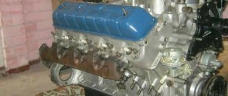
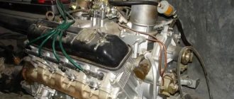
The six cylinders of the MMZ D-260 engine are placed vertically in an in-line arrangement. The direction of rotation of the crankshaft is right (clockwise). The engine is four-stroke, equipped with direct fuel injection, liquid cooling, a turbocharging system and intercooling of charge air. Certified according to GOST-17.2.2.02, GOST-17.2.2.05, OST-23.3.23 and GOST-2000.
Depending on their purpose, diesel engines of this brand can be equipped with the following additional assembly units: a pneumatic compressor, a gear power steering pump with a drive, and clutch disc assemblies. When installed on a tractor, the MTZ “D-260” is equipped with a water radiator, electrical equipment and control devices.
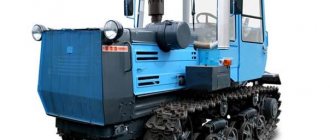
"D-260" "under the hood" of the Belarus MTZ-1221 tractor.
Specifications
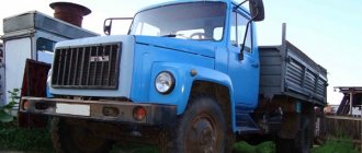
Possessing high technical characteristics, the D-260 power unit was ideal for installation on tractors and trucks. The main application of the motors was on T-150 tractors and combine harvesters. In this case, it was necessary to additionally equip the power unit with a water and oil radiator.
D260 engine on T-150
Let's consider the main technical characteristics of the motor:
News
Replacement of fuel injection pump on MMZ D-260.4, D-260.4S, D-260.3 engines
The breakdown of any equipment is one of the unpleasant moments that stops the work process. The most expensive repair is engine maintenance. In order to avoid getting into a difficult and “expensive” situation, it is necessary to diagnose and repair failed parts in advance.
One of the common causes of unstable engine operation is the failure of the high pressure fuel pump.
In this article we will look at the injection pump 365.1111005-40.04 of the Compact 32 family, its analogues and the procedure for replacing it.
A high-pressure fuel pump is one of the important elements of the engine, responsible for supplying precisely measured portions of fuel to the cylinders at a certain pressure and at a certain point in the cycle, corresponding to a given load applied to the crankshaft.
Fuel injection pump 365.1111005-40.04 of the Compact 32 family is a high-pressure fuel pump with a vertical in-line arrangement of plunger pairs, the number of sections is 6, the intersectional distance is 32 mm. This high pressure fuel pump is used for diesel engines with a cylinder capacity of up to 1.5 liters and a power of up to 30 kW per cylinder. Fuel injection pump 365.1111005-40.04 allows for cyclic flow up to 160 mm and fuel injection pressure from 450 to 1100 ba. They are equipped with a mechanical all-mode and single-mode speed controller. The external speed characteristics of the engine are formed by a forward, reverse, and boost corrector.
High-pressure fuel pump 363.1111005-40.04 manufactured by YaZDA OJSC (YaMZ), Yaroslavl, is used on the following types of equipment:
— Combine harvester "Gomselmash" KSK-100A with MMZ D-260.4 D-260.4S2 engine,
— Belarus-2022 tractor with MMZ D-260.4 D-260.4S2 engine,
EURO fuel injection pump 1 363.1111005-40.0 is interchangeable:
— High pressure fuel pump TNVD 632.1111007-24 NZTA Noginsk (D-260.4S)
— High pressure fuel pump injection pump RR6M10R1f-3493 Motorpal Czech Republic (D-260.3)
The procedure for replacing the MOTORPAL injection pump with the NZTA injection pump, YaMZ OJSC:
Work on reinstalling pumps should be carried out on an engine that has been cleared of dust and dirt and thoroughly washed.
The iron horse is not a plowman, not a blacksmith, not a carpenter, but the first worker in the village.
About the history of the enterprise and the MMZ D-260 engine
The history of the Minsk Motor Plant is closely connected with the history of another glorious Belarusian enterprise - the Minsk Tractor Plant. Built immediately after the Great Patriotic War, MTZ rapidly developed and increased its production. In 1960, a decision was made to build a plant for the production of diesel engines in Minsk. First of all, for the new model of the MTZ-50 tractor, in the amount of 120 thousand D-50 engines per year.
The Minsk Motor Plant was built in just over two years, on the north-eastern outskirts of Minsk between the tractor and bearing factories. Serial production of D-50 motors started at the enterprise in July 1963. Starting next year, all MTZ Belarus tractors began to be equipped with Minsk-made engines.
Alexander Lukashenko is a frequent guest at Belarusian enterprises, including MMZ.
In total, the list of MMZ partner enterprises, which are consumers of its products, includes 44 factories and firms. Most of them, of course, are in Russia and Belarus; Ukraine, Uzbekistan, Kazakhstan and Poland are also represented.
Technical characteristics of the “D-260” in numbers and a list of its modifications
Currently, the price list on the official website of the Minsk Motor Plant presents to the attention of potential consumers fourteen modifications of the D-260 diesel engine. Namely: “D260.1-305”, “D260.1S2-333”, “D260.1S-394”, “D260.1-305”, “D260.1-306”, “D260.1-308” , "D260.1-339", "D260.1-358", "D260.1-372", "D260.1-380", "D260.1-406", "D260.1-407", " D260.1-417", "D260.1-443".
MMZ D-260 engines are equipped with starters 3002.3708 (24V), generators G9945.3701-1 (28V), turbochargers TKR-7-00.01 (BZA, Borisov, Belarus), high-pressure fuel pumps PP6M10P1f-3491" ("Motorpal", Jihlava, Czech Republic), or "YAZDA 363.1111005-40" (Yaroslavl), water pumps "260-1307116-A", oil pumps "260-1011020".
Maintenance and oil change
The D-260 engine, in terms of maintenance, does not have significant differences from its younger brothers 240-245 models. Engine maintenance is carried out every 20-25 thousand kilometers.
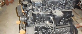
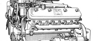
Main elements of the D-260 engine
Scheduled maintenance of an internal combustion engine is a set of operations aimed at preserving the primary condition of the components and parts of the unit.
According to the repair and operation manual for the D series motor compiled by the manufacturer, we will consider what operations are included in the maintenance of the 260th:
- Change of oil.
- Adjusting the valve mechanism.
- Replacing filters. So, depending on the engine modification, the following filter elements may or may not be present: a fine and coarse oil filter, a filter element for coarse and fine fuel purification, an air filter, an eco-filter for exhaust.
- Cleaning the injectors.
- Adjustments related to the high pressure fuel pump.
- Other operations aimed at maintaining the power unit.
Servicing a high-pressure fuel pump is a separate set of operations that can only be done efficiently by specialists in the repair of fuel equipment for diesel engines.
Installation of injection pump on the D 260 engine
Checking and adjusting the fuel injection timing advance angle
If it is difficult to start a diesel engine, there is a smoky exhaust, as well as when replacing and installing a fuel pump after adjustment on a stand or repair, be sure to check the setting angle of the fuel injection advance on the diesel engine.
Check the angle in the following sequence:
a) for high pressure fuel pumps mod.363.1111005-40
• set the piston of the first cylinder on the compression stroke 30 - 40° to the position of the required installation angle of injection advance on the scale on the damper body;
• set the stop lever and the regulator control lever to the position corresponding to the maximum fuel supply;
• disconnect the high-pressure tube from the fitting of the first section of the pump and instead connect a control device, which is a piece of high-pressure tube 50.70 mm long with a pressure nut at one end and the other end bent to the side by 90° (Figure 25);
Figure 25 — Sketch of the control device
1 - pressure nut; 2 - high pressure pipe
• fill the fuel pump with fuel, remove air from the low pressure system and create excess pressure with a manual pump until a continuous stream of fuel appears from the control device tube;
• slowly rotating the diesel crankshaft clockwise and maintaining excess pressure in the pump head (boost pump), watch for fuel flowing out of the control device. When the fuel stops flowing out (up to 1 drop is allowed in 10 seconds), stop rotating the crankshaft;
• determine the position of the graduated scale on the damper body 2 relative to the mounting pin 3, fixed to the distribution cover 1 (Figure 26).
Figure 26 — Setting the fuel injection advance angle.
1 — distribution cover (manhole cover removed); 2 — silicone damper; 3—locating pin; 4 - pulley
If the pin is in the graduation range “19. 21" on the graduated scale, then the fuel supply start angle is set correctly, i.e. The piston of the first cylinder is set to a position corresponding to 19.21° before TDC.
If the pin is not within the specified range, make an adjustment by doing the following:
• rotating the crankshaft, align the “20” mark on the graduated scale of the damper housing with the alignment pin;
• remove hatch cover 1 (Figure 4);
• loosen the nuts securing the fuel pump drive gear to the drive coupling half by 1.1.5 turns;
• using a wrench, turn the fuel pump shaft counterclockwise by the nut until the pins stop against the edge of the groove of the fuel pump drive gear;
• create excess pressure in the fuel pump head until a continuous stream of fuel appears from the control device tube;
• turning the pump shaft clockwise and maintaining excess pressure, watch for fuel flowing out of the control device;
• when the fuel stops flowing out, stop rotating the shaft and fix it by tightening the nuts securing the drive gear to the drive coupling half.
Recheck the timing of the start of fuel supply.
Disconnect the control device and reinstall the high pressure pipe and manhole cover.
b) for high pressure fuel pumps PP6M10P1f-3491; PP6M10P1f-3492
• set the regulator control levers to the position corresponding to the maximum fuel supply;
• disconnect the high-pressure tube from the fitting of the first section of the pump and instead connect a momentoscope (a union nut with a short tube, to which a glass tube with an internal diameter of 1.2 mm is connected using a rubber tube);
Installation of valve overlap of the first cylinder
It's written in the instruction manual. What is necessary is to bring the piston of the first cylinder to top dead center when the valves close. This causes confusion about what needs to be done.
In fact, everything is very simple.
Installing the piston at TDC
When the piston of the first cylinder is brought to top dead center. There are two possible valve behavior options. During one work cycle, the crankshaft makes two revolutions. Accordingly, the piston approaches TDC twice. The compression stroke occurs once. Both valves are completely closed. Since it is necessary to create compression in the combustion chamber. The second time is the exhaust stroke. The exhaust valve closes at TDC after passing TDC the intake valve opens. For air intake in case of a diesel engine and fuel mixture in case of a gasoline engine.
To adjust the valves on the D260 engine, it is proposed to set the piston of the first cylinder to TDC when the compression stroke ends and the air intake begins.
In practice it will look like this. Rotate the crankshaft until the exhaust valve begins to close. The valve is closed, turn it a little more and the exhaust valve opens. Then move the crankshaft back so that both valves are closed. You can check yourself on the sixth cylinder. The piston in it will also approach the top dead center. At the moment when the piston moves upward, both valves are closed and stationary.
The compression stroke will occur in the sixth cylinder. And at this moment the valves on the sixth cylinder can be adjusted.
There is no need to remove the injectors when adjusting the valves. But it is required to bring the pistons of the first and sixth cylinders as accurately as possible to TDC.
Installation according to the mark on the pulley
To do this, there is a TDC mark on the pulley; it must be aligned with the alignment pin.
Design and basic parts of MMZ D-260
Cylinder block of the D-260 engine
The cylinder block of the D-260 engine is the main body part, made in the form of a monoblock, which is a rigid casting of cast iron. The block bores contain six removable sleeves made from a special grade of cast iron.
Each liner is mounted in the cylinder block along two centering belts. In the upper belt the liner is secured with a collar, and in the lower belt it is sealed with two rubber rings placed in the grooves of the cylinder block. Coolant circulates between the walls of the MMZ D-260 cylinder block and the liners. There are special bosses on the transverse partitions of the cylinder block, which are intended to form supports for the crankshaft. Covers are installed on these tides. The bosses together with the covers form places for installing the main bearings. The beds for the main bearing shells are bored in one installation, complete with covers. These covers cannot be swapped.
Multifunctional loader "Amkodor 332S4" with a "D-260" engine.
The MMZ D-260 cylinder block is equipped with a longitudinal oil channel, from which oil is transported through transverse channels to the crankshaft main bearings, and then to the camshaft journals and to the injectors, cooling the pistons. Piston cooling nozzles are installed in the upper part of the cylinder block, in the second, fourth and sixth crankshaft bearings. On the water distribution channel of the cylinder block there is a platform for mounting a liquid-oil heat exchanger. The supply and removal of oil from the heat exchanger is carried out through channels in the block.
To increase rigidity, the lower plane of the cylinder block is shifted downward by 80 millimeters, relative to the crankshaft axis. A steel distribution board and distribution cover are attached to the front end of the block, and a sheet of steel is attached to the rear end, through which the power unit is connected to the frame of the tractor or combine. 2 brackets, which are located on the side surfaces of the cylinder block, are also the front engine support. The bottom of the cylinder block is covered with an oil sump.
Heads in the cylinder block of the D-260 engine
The MMZ D-260 cylinder heads are cast from cast iron and are interchangeable (one head fits three cylinders). The internal cavities of these cylinder heads are equipped with inlet and outlet channels, which are closed by valves.
To ensure heat dissipation, the cylinder heads are equipped with internal cavities in which coolant circulates. The cylinder heads have plug-in valve seats. They consist of a special heat-resistant and wear-resistant alloy.
"D-260" on the next modification of the "T-150" tractor.
Three injectors are installed on each cylinder head. Also mounted here are the rocker arm axles and the rocker arms themselves, struts, head covers with caps covering the valve mechanism. To seal the connector between the heads and the cylinder block, a gasket made of asbestos-free fabric is provided. The holes for the cylinder liners and the oil channel are edged with sheet steel. Additional edging of the cylinder holes of the gasket with fluoroplastic rings is carried out during the engine assembly process.
Engine crank mechanism
The engine crank mechanism includes: a crankshaft with main and connecting rod bearings, a flywheel, pistons with piston rings and pins, connecting rods. The crankshaft “D-260” is made of steel; it has 7 main journals and 6 connecting rod journals. To compensate for the loads on the bearings from inertial forces, removable counterweights are installed on the first, sixth, seventh and twelfth cheeks of the crankshaft. Cavities are made in the connecting rod journals for additional centrifugal oil purification. The cavities of the necks are covered with threaded plugs.
Four bimetallic (steel-aluminum) half rings installed in the bores of the cylinder block and the cover of the fourth main bearing absorb the axial force of the D-260 crankshaft. The engine crankshaft is sealed with cuffs on the front and rear sides.
The following are installed on the front edge of the shaft: with interference – the timing gear (crankshaft gear) and the oil pump drive gear; drive pulley for a water pump, generator, air conditioning compressor (if we are talking about the energy-rich MTZ-1221 tractor). In order to reduce the level of torsional vibrations of the crankshaft, a silicone damper is mounted on the pulley hub.
The pistons of the MMZ D-260 engine are made of aluminum alloy. A combustion chamber is provided at the bottom of the piston. In the upper part of the pistons there are 3 grooves - compression rings are installed in the first 2 of them, and an oil scraper ring with an expander is installed in the 3rd. The hollow piston pins are made of chrome-nickel steel. The movement of the fingers along the axis in the piston bosses is limited by special retaining rings.
The connecting rod of the D-260 engine is made of steel, I-section. The bushing is pressed into its upper head. The piston pins are lubricated through special holes in the bushing and the upper head of the connecting rod. Boring of the lower head of the connecting rod for the bearings is carried out together with the cover. The connecting rod and the cap have the same numbers stamped on their surfaces. The connecting rod caps are not interchangeable.
There are also certain weight groups of connecting rods, based on the mass of their lower and upper heads. And the engine must be equipped with connecting rods of an identical weight group. Thin-walled liners for the connecting rod and main bearings of the crankshaft are made from a bimetallic strip. According to their inner diameter, the liners are made in two sizes, identical to the crankshaft journals.
The flywheel is made of cast iron and is bolted to the crankshaft flange. Steel gear rims are pressed onto the D-260 flywheels.
Gas distribution mechanism of the D-260 engine
The gas distribution mechanism of the MMZ D-260 diesel engine consists of gears, a camshaft, intake and exhaust valves, as well as parts for their installation and drive: pushers, rods, rocker arms, adjusting screws with nuts, plates, crackers, springs, struts and rocker arm axles.
The camshaft here is 4-bearing; it receives rotation from the crankshaft through distribution gears. The pushers are made of steel, with spherical bottoms, coated with special cast iron. The camshaft cams are made with a certain slope, due to which the pushers make rotational movements during operation.
Diesel engines of trucks and tractors. Spare parts, adjustments and repairs.
________________________________________________________________
___________________________________________________________________________
Electrical equipment and disassembly of diesel engine D-260
Electrical equipment and starting system for the D-260 diesel engine Among the electrical equipment units on the diesel engine, a generator G964.3701-1 or G964.3701-1-2 with a power of 1000 W and a rated voltage of 14V is installed. The diesel engine also provides for the installation of a generator G994.3701-1 with a rated voltage of 28V and a power of 1000 W. The generator is a non-contact five-phase like-pole electric machine with one-sided electromagnetic excitation, a built-in rectifier unit and an integral voltage regulator. The generator is driven by a V-belt from the crankshaft pulley. The generator drive gear ratio is 2.18. The starting device for diesel D-260 Amkodor loaders, MTZ tractors, MAZ buses consists of an electric starter 20.3708 or ST142N with a rated voltage of 24V and a power of 6 kW. On diesel engines D-260.9 and D-260.14, it is also possible to install an ST-142M starter with a rated voltage of 12V and a power of 3.5 kW.
The starter is a mixed-excitation DC electric motor with an electromagnetic relay and drive mechanism. To ensure starting at low ambient temperatures, the engine design provides for the possibility of using an aerosol starting device for injecting a flammable liquid. For this purpose, the intake manifold has a K1/8″ hole for installing a starting device injector. Checking the starter and generator of the D-260 diesel engine Every 2000 hours of diesel operation, remove the starter from the diesel engine, clean the outer surface of the starter and traction relay from dust and dirt. Remove the protective cap and check the condition of the commutator, brushes and starter relay contact system.
The brushes must move freely in the brush holders and fit tightly to the commutator. If the brushes are worn to a height of 10 mm, or if there are chips, replace them with new ones. If the D-260 starter commutator is dirty, wipe it with a clean cloth soaked in gasoline. If the commutator is scorched, clean it with fine-grained sandpaper or grind it on a machine. To check the electromagnetic relay contacts, remove the cover.
If the contact bolts and disk are burnt, clean them with fine-grained sandpaper or a fine-notched file, without disturbing the parallelism of the contact surfaces. If there is a lot of wear on the contact bolts at the points of contact with the contact disk, turn the bolts 180 degrees and turn the contact disk over to the other side. Check the condition of the starter drive gear teeth, thrust half-rings and the diesel flywheel ring. Lubricate all rubbing parts of the starter with engine oil. If necessary, adjust the gap between the end of the drive gear and the thrust half-rings, which should be within 2...4 mm when the relay armature is in the on position.
To adjust the gap, loosen the lock nut and turn the eccentric axis of the lever to set the gap to 3-1 mm, tighten the lock nut. During operation of the D-260 diesel engine of Amkodor loaders, MTZ tractors, MAZ buses, special generator maintenance is not required.
Seasonal adjustment of the generator voltage is carried out with the “Winter-Summer” voltage adjustment screw located on the rear wall of the generator. During operation, ensure that the generator and wires are securely fastened, as well as the cleanliness of the outer surface and terminals. Check the serviceability of the D-260 MMZ engine generator using the control lamp and ammeter installed on the instrument panel of the MTZ-1221 tractor. If the generator is in good working order, the warning lamp lights up when the ground switch is turned on before starting the diesel engine.
After starting the diesel engine and when it operates at average speed, the warning lamp goes out, and the ammeter should show a certain charging current, the value of which drops as the battery charge is restored. Basic instructions for disassembling and assembling the MMZ D-260 diesel engine When disassembling the diesel engine, remove the pistons and connecting rods only upwards. Before removing the pistons, remove carbon deposits from the top of the cylinder liner. When replacing parts of the sleeve-piston group and the crank mechanism, pay attention to the size groups of the parts.
Cylinder liners according to the inner diameter and pistons according to the outer diameter of the skirt are sorted into three size groups (B, S, M) in accordance with the table. The group designation is applied on the lead-in cone of the liner and on the piston bottom. Group markings Liner diameter, mm Piston skirt diameter, mm B 110+0.06 110-0.05 C 110+0.04 110-0.07 M 110+0.02 110-0.09 Select as a set for one diesel engine pistons, connecting rods and piston pins are of the same weight group; the weight of connecting rods complete with pistons should not exceed 30 g per diesel engine. The main and connecting rod journals and crankshaft bearing shells are manufactured in two nominal sizes: Designation of the nominal bearings Shaft journal diameter (main/connecting rod), mm 1N 85.25-0.085 / 73.00-0.100 2N 85.00-0.085 / 72.75- 0.100 Crankshafts, the connecting rod and main journals of which are made according to the size of the second rating, have an additional designation on the first cheek: “2K” - main journals of the second rating; “2Ш” - connecting rod journals of the second rating; “2KSh” - connecting rod and main journals of the second rating. Each piston of the D-260 MMZ engine is equipped with an upper trapezoidal compression ring, one compression cone ring and one box-type oil scraper ring with a spring expander.
The compression rings on the end surface of the lock are marked “TOP”, which should face the piston bottom when installing the rings. The joint of the oil scraper ring expander must not coincide with the ring lock. Place the piston ring locks at equal distances around the circumference
Fig. 1 — Diagram of installation of timing gears D-260 1-crankshaft gear; 2 - intermediate gear; 3- fuel pump drive gear; 4 - camshaft gear; 5- oil pump drive gear Install the distribution gears according to the marks on them. The marks on the intermediate gear must be aligned with the corresponding marks on the crankshaft and camshaft gears and the fuel pump drive gear in accordance with Figure 1.
Install the oil pump drive gear heated to a temperature of 150...200C, after aligning all the marks. When installing the cylinder head gasket, replace the fluoroplastic rings.
___________________________________________________________________
___________________________________________________________________
- Injection pump D-245 - design and adjustments
- Timing belt and valves D-245
- Engine lubrication system D-245
- Fuel system parts D-245
- Operations for adjusting YaMZ-236
- Operations for disassembling and installing fuel injection pump YaMZ-236
- Cooling system and lubrication system YaMZ-238
- Fuel injection pump YaMZ-238
- Characteristics of Cummins ISBe, ISLe, ISB, QSB
___________________________________________________________________
___________________________________________________________________
- Repair and replacement of Cummins ISBe, ISLe, ISB crankshaft
- Cummins ISBe, ISLe, QSB cylinder block repair
- Connecting rod and piston group Cummins ISBe, ISLe, ISB
- Diesel cooling system ISF 2.8
- ISF 2.8 diesel cylinder block and pistons
- Cummins ISF 3.8 Fuel System Components
- Cummins 3.8 engine lubrication system
- Cummins ISF 3.8 Cooling System
- Cylinder head YaMZ-7511
- YaMZ-7511 cylinder block
- Diesel crankshaft YaMZ-7511
Device D-260
The structural basis of the engine is a cast iron cylinder block. Attachment to the vehicle is carried out from the rear end; the shield and distribution cover are located at the front. The gasket between the block and the head is made of asbestos-free fabric. The block heads are interchangeable. The tightening torques of the fastening bolts are 190–210 Nm. The valve mechanism is closed with caps. The valves are adjusted using a special device.
Fuel supply system
The crankshaft rests on the side walls and internal partitions. Torque is transmitted to the camshaft via distribution gears. The camshaft has four fulcrum points. The camshaft cams are installed at an angle, due to which the tappets rotate. The pistons are made of aluminum alloy; the combustion chamber of the fuel-air mixture is located in the bottom. Compression and oil rings are installed on the top of the pistons.
The lubrication system is a system of longitudinal and transverse channels through which oil is supplied to the bearings, camshaft and injectors. The oil sump is located at the bottom. Coolant circulates between the walls of the MMZ D-260 cylinder block and the liners. The system is closed type, circulation is provided by a centrifugal pump. The system includes a remote thermometer, a warning light and two thermostats.
Fuel supply is provided by Yaroslavl-made fuel pumps (high pressure). The six-section pump ensures precise dosage of fuel into each cylinder at optimal pressure. The pressure is regulated by a bypass valve. It is possible to manually remove air from the system using a special pump. The fuel goes through two stages of purification - coarse and fine. The air is purified in three stages: a monocyclone and two paper filters. The engine is equipped with a turbocharger consisting of a centripetal radial turbine and a centrifugal single-stage compressor. The energy of exhaust gases is used to supply air to the cylinders.
Be sure to read: Carrying capacity of Renault Master (Renault Master)
Reliability, problems and repairs of the D-260
The six-cylinder diesel engine from MMZ was released in 1992 and was equipped with an in-line cast-iron cylinder block with cast-iron wet liners and oil nozzles for cooling the pistons. In this block, engineers placed a steel crankshaft with a piston stroke of 125 mm (diameter of main journals 85.25 mm, crankpins 73 mm), steel connecting rods and aluminum pistons with a diameter of 110 mm. All this allows you to get a working volume of 7.12 liters. Oil pressure - 2.8-4.5 kgf/cm2.
The cylinder block is covered by a cast iron head with 12 valves and inserted valve seats. There is no camshaft in the cylinder head - it stands in the block and acts on the valves through pushers, rods and rocker arms. The intake valves are 48 mm, exhaust valves are 42 mm, and the stem thickness is 11 mm. Adjustment of the D-260 valves is required as necessary, but the clearances must be checked after every 500 hours of operation. The valve clearances should be as follows: intake - 0.25 mm, exhaust - 0.45 mm. The procedure for adjusting the valves is the same as the operating sequence of the internal combustion engine - 1-5-3-6-2-4.
The D-260 diesel engine is equipped with a YAZDA 363 fuel pump and a TKR 7 turbocharger. Since 1998, production of a version under the Euro-1 standard began, and in 2001 the D-260 diesel engine was brought up to Euro-2. This was followed by Euro-3 engines, which entered the production line in 2005 and were distinguished by the presence of Common rail injection with a Bosch CRN2.2 fuel pump and a Bosch EDC7UC31 ECU.
Modifications of D-260 and their differences
1. D-260.1 - the main modification with TKR-7N3 (Euro-1), TKR-700-4 (Euro-2) without an intercooler with an output of 155 hp. at 2100 rpm, and the torque is 622 Nm at 1400 rpm. 2. D-260.2 - analogue of D260.1 without an intercooler with a power of 130 hp. at 2100 rpm, torque 500 Nm at 1400 rpm. 3. D-260.4 - combine engine with a TKR 700-2-12M turbine and an intercooler and a power of 209 hp. at 2100 rpm, torque 808 Nm at 1500 rpm. 4. D-260.5 - engine with intercooler for equipment weighing up to 32 tons. Its power is 230 hp. at 2100 rpm, torque 883 Nm at 1300-1600 rpm. 5. D-260.6 - diesel for combines and tractors with a power of 206 hp. at 2100 rpm, torque 1000 Nm at 1500 rpm. 6. D-260.7 - combine engine based on 260.1, but with different intake and exhaust manifolds, with an NSh-25 pump, a modified engine support, with its own oil supply and oil drain from the turbine. There is a TKR 700-2-12M turbocharger with an intercooler and developing 250 hp. at 2100 rpm, torque 961 Nm at 1500 rpm. 7. D-260.8 - version without intercooler for 102 hp. at 1800 rpm, torque 497 Nm at 1500 rpm. 8. D-260.9 - combine engine with intercooler and TKR 700-2-12M. The engine is based on the 260.1 and features an NSh-32 pump. Its power is 180 hp. at 2100 rpm, torque 690 Nm at 1500 rpm. 9. D-260.11 - 185 hp car engine. at 2100 rpm, torque 745 Nm at 1500 rpm. 10. D-260.12 - engine for trucks weighing up to 36 tons, developing a power of 250 hp. at 2100 rpm and torque 970 Nm at 1500 rpm. 11. D-260.13 - automobile internal combustion engine with 204 hp. at 2100 rpm, torque 768 Nm at 1300-1575 rpm. 12. D-260.14 - diesel for tracked tractors with a 140 hp intercooler. at 1800 rpm, torque 682 Nm at 1300-1450 rpm. The motor is based on 260.1 and has a starter, generator and pump drive. 13. D-260.16 - engine with 280 hp intercooler. at 2100 rpm, torque 1124 Nm at 1500 rpm.
Reviews about the MMZ D-260 engine
There are few reviews about the specific practical application of the D-260 engines, and they are very ambiguous. Since this engine performs well as a power unit for energy-saturated tractors and road-building equipment, it is not very suitable for use on heavy-duty “long-range” trucks.
The President of Belarus is presented with a model of the engine during his visit to MMZ.
In this area, it is inferior to the traditional YaMZ-236 and has not received serious distribution (except for “single” (without a trailer) MAZs for the domestic Belarusian market). Despite the fact that the MMZ D-260 costs less than the YaMZ-236.
Price of the MMZ D-260 engine
The price of the new D-260 engine starts at 430,000 rubles. First (as the price increases) in the list are modifications intended for electrical units and road cars; then, more expensive - for the MTZ-1221 and MTZ-1523 tractors; further – for motor graders, pumping units, Polesie KZS-7 and Niva Effect combines. These modifications cost 480,000 rubles in the official price list. There are also offers for the sale of D-260 engines after major overhauls. Prices for such motors start at 150 thousand rubles.
Source
Engine D 260 MMZ: Design and technical characteristics
The engine plant in Minsk is known outside the commonwealth; the D 260 engine played a significant role in the glorification of the enterprise. The power plant began to be produced relatively recently, the first samples left the assembly line in 1992. Users reacted favorably to the motor, putting the product on a par with the renowned product of the Yaroslavl plant “YaMZ-236”.
A diesel engine with six chambers has proven itself to be a reliable, trouble-free, versatile unit. As a result, tens of thousands of copies of the product were released in a short period of time. Trying to make the product universal, the designers created a line of modifications that are used not only on self-propelled units, but also on harvesting machines, buses, and trucks. The 260 engine is durable with an increased service life and is operated in the temperature range (+40/-45°C), which makes the device a sought-after and popular product.