The A 41 four-cylinder diesel engine is manufactured by the Altai Motor Plant and is intended for installation on heavy construction equipment and agricultural vehicles.
This power unit has proven itself to be extremely reliable, durable and easy to maintain, which has invariably affected its popularity.
About the main technical parameters
A41 is a series that features naturally aspirated diesel engines equipped with four cylinders. Construction and agricultural machinery is where such units are most often used. The unit is distinguished by its unpretentiousness and high build quality. Another advantage is good maintainability. Due to this, consumers give preference to such units.
The following technical characteristics of the A41 engine are present in stock versions:
- 12 thousand engine hours of declared working life.
- Supply of two gear hydraulic pumps, with the addition of a crankshaft drive with a gear type transmission.
- 2 valves in the gas distribution mechanism.
- DC unit, designated 214A1, 7=G304.
- In winter, DS-8 oil is used, in summer - DS-11.
- The use of a liquid cooling system for the engine.
- 1.62 kWh – fuel consumption indicator.
- 412 Nm at 1300 rpm – torque level.
- 16 is an indicator for the standard compression ratio.
- Each individual cylinder has a 130mm diameter.
- 140 mm piston stroke length.
- Cylinders installed vertically.
- The total number of cylinders is 4. The indicator is different if we consider, for example, the ZMZ 41 engine.
Engine A41: where can it be installed
This type of unit is present in:
- Pumping units.
- Graders.
- Power plants.
- Excavators.
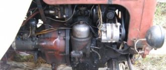
Connection with other types of equipment is also allowed if plant representatives do not object. The engine is used on tractors of the T-4A, DT-75M, T-4 series. The GAZ 41 engine also became popular.
Main features, overview information
If the engine is 90-horsepower, then it will have a cylinder volume of 7.43 liters. Thanks to this, serious power appears even at relatively low speeds. The developers are trying to follow the latest trends characteristic of the motorcycle industry. Therefore, a direct injection system was built into the control system unit. This means that only electronic systems control the fuel supply.
Another important feature is the use of a gas distribution mechanism with two valves. Engineers used this part to give maximum efficiency to their engine. The output and efficiency of the device have also improved, which is proven by numerous photos; the A 41 engine gets better with each modification.
High-strength cast iron sleeves add to the overall reliability of the unit. Their surface is treated with a special method - vertex honing. The cooling system becomes more sophisticated, and the overall working life increases. But we must remember about weight gain. The main element of the cooling system is the oil-liquid heat exchanger. It cools the engine equally well both in idle mode and in the presence of additional loads. Engine stability has been greatly improved due to the fact that it is now able to maintain a stable, comfortable temperature. This helps the clutch of the A 41 engine work better.
What other parameters deserve attention?
Among the interesting parameters is that the valves rotate during engine operation when they are acted upon by their own springs. This is due to vibrations that accompany standard operating conditions. Valve engines are considered more reliable, so this design can be considered an advantage of the device.
The heaviest loads usually fall on the camshaft. Therefore, its hardening involves the use of high-frequency currents. The operation of the mechanism is ensured by 12 cams and 7 necks, which are located inside.
The unit begins to move when interacting with the crankshaft. Gear transmission takes part in this process.
The environmental friendliness of the power unit is another issue that the developers have seriously thought about. Units that have left production have no violations in the direction of emission of harmful substances into the atmosphere. Therefore, the lubrication system of the A 41 engine remains reliable.
How to set the ignition correctly
Incorrect installation of the ignition on any type of engine: carburetor or injection, leads to a number of problems. These include engine overheating, deterioration of vehicle dynamics, excessively toxic exhaust, and rapid wear of power unit parts. The ignition installation on carburetor, injection engines and power units with gas equipment (LPG) differs from each other. This is due to different characteristics of the mixture’s ignition. Therefore, each option on how to correctly set the ignition for a specific engine type should be considered separately.
Installing the ignition on a VAZ (“classic”)
They are equipped with one of two types of ignition. The first is contact: here the opening is carried out by turning the distributor shaft (mechanical method). The second type of ignition is electronic, non-contact: it uses a Hall sensor, which determines the time of spark formation.
How the ignition system works
When the piston reaches the TDC position, it compresses the combustible mixture with maximum force. At this time, a high voltage is formed in the coil. From the distributor cover it is supplied through high-voltage wires to the spark plugs, where a spark is formed that ignites the mixture. When the crankshaft speed increases, the ignition timing changes. This procedure is “carried out” by a vacuum regulator (attached to the ignition distributor), connected via a tube to the intake manifold. As a result, optimal power is achieved in any engine operating mode.
Regarding modifications
Depending on what special equipment is used, various engine modifications are used.
The main models will be:
- On the DT-75 tractor, A-41I, SI, S are used.
- A-41 D is suitable for forklifts and rollers.
- A 41-G – modification for drilling rigs and graders, asphalt pavers.
- Pumping stations require the use of the A-41 B series.
Basic models are often installed on tractors or any other equipment agreed with the manufacturer. The motor is available in more than 11 modifications. The following additional equipment can be used:
- Enlarged heat exchanger for the engine oil cooling system.
- Pre-starting electric torch heater.
- Pneumatic compressor.
- Silencer.
- Clutch block coupling with modernization.
- Two hydraulic pumps instead of one.
The location of the cylinders is also different for modifications. The latest models have an in-line layout, thanks to which the rated power increases to 100 horsepower. The torque reserve has been increased to 20%. The clutch adjustment in the DT 75 has a special effect. The A41 engine shows its advantages under various circumstances.
USEFUL TIPS Issue 10. Ignition of the PD10 starter. Starting motor magneto
Ignition of the working mixture in the cylinder of the starting engine is carried out using an electric discharge generated by the electrodes of a spark plug. To create a good discharge, a fairly high voltage is required (about 10-15 kV). Such a voltage can be created by a magneto, which acts as an alternating current generator, breaker and transformer.
Launcher Magneto
The PD 10 starting engine uses a right-handed M124-B1 magneto with a constant spark formation moment (ignition timing is 27º). The magneto is driven using a rigid coupling half from the starting motor drive gear.
The magneto body is made of zinc-based alloy. The rotor, which is the main part of the alternating current generator and is designed to generate and change the magnitude of the magnetic flux that passes through the core, is mounted on two ball bearings between the pole shoes of the magnetic circuit. The rotor structure includes two rollers and a package of lamellas pressed onto a magnet. The magnet with lamellas and rollers are filled with zinc alloy.
Magneto launcher PD 10: 1 - housing; 2 - rotor; 3 — magneto cover; 4 - transformer; 5 - high voltage output; 6 — breaker cover; 7 - cam; 8 - capacitor; 9 - half coupling; 10 — breaker lever; 11 — contact stand; 12 — remote shutdown terminal; 13 — shutdown button; 14 - felt.
Magneto transformer
The transformer is designed to create high voltage current. Its main component is the core, consisting of separate plates of electrical steel, primary and secondary windings. The end parts of the windings are protected by getinax cheeks. One of the cheeks of the transformer is equipped with a tip to which the end of the primary and the beginning of the secondary winding are soldered. The tip is connected to the contact post of the breaker. The end of the secondary winding is soldered to the electrode through a protective tape. The secondary winding consists of a large number of turns of thin wire, and the primary winding consists of a small number of turns of thick wire. To improve the electrical strength, the transformer is impregnated with turbine oil.
The breaker connects a cam located on the rotor shaft with a contact post and a lever with tungsten contacts. These elements, together with a filter for lubrication of the cam, are located in the magneto cover. When the magneto rotor rotates, the cam breaks the contacts of the breaker, thereby forming a gap of 0.25-0.35 mm.
Magneto operating principle
During rotation of the rotor, a magnetic flux of varying direction and magnitude is formed in the transformer core and the magnetic circuit of the housing, crossing the turns of the primary winding of the transformer and creating an electromotive force in it. Under the influence of this force, a low-voltage alternating electric current is created in this winding.
When the current reaches its maximum value, the breaker is triggered, breaking the current in the primary winding. The electric current in the windings instantly disappears, the magnetic flux quickly decreases and simultaneously forms a high-voltage electromotive force in the secondary winding, under the influence of which a spark discharge is created between the electrodes of the spark plug, which is necessary to ignite the working mixture in the starter cylinder PD 10.
To reduce burning of the breaker contacts when they open, a capacitor is connected in parallel to them. To protect the transformer from breakdown when the high voltage wire breaks or is disconnected, the magneto has a spark gap between the magneto body and the high voltage electrode.
About maintenance
There should not be any serious problems when servicing the units. The driver can perform the work independently:
- Oil pressure and temperature are the only indicators that require constant monitoring. The current lubrication level requires periodic monitoring. The oil filter needs to be washed from time to time. Every 240 minutes the fluid used must be replaced.
- Every day the engine is serviced by different shift workers. Or the event is held every 8-10 engine hours. The tightness of connections and fastening elements must be checked and cleaned from dirt and dust. Separately monitor extraneous noise, adding fuel and water.
The cooling system cannot do without regular maintenance. The system must be flushed to remove scale. Additional sealing is applied when a leak appears.
Maintenance
As already mentioned, the A 41 and its modifications are unpretentious in terms of operating conditions and service. A qualified technician can easily handle routine maintenance tasks on his own.
In fact, for long and uninterrupted operation of the engine, it is necessary, mainly, to monitor the oil temperature and pressure in the oil line, not allowing the lubricant level to fall below a critical level, and wash the oil filter. Oil changes are carried out regularly, every 240 engine hours.
An important regular operation is clutch adjustment, since with gradual wear of the disc linings, the outlet clearances of the middle disc and the free play of the clutch increase. Schematic design of the clutch using the example of that in the DT-75 tractor:
This is a dry double-disc clutch of a permanently closed type. Adjustment of the DT 75 clutch with the A 41 engine should be carried out, if necessary, based on the test result, approximately every 240 operating hours.
Over time, it may also be necessary to adjust the valves of the A 41 engine. A gap of 0.25 ... 0.3 mm is allowed for both valves of this engine.
The motor should also be serviced every shift, at the end of the shift or before the start. The current service interval is about 10 engine hours. The set of manipulations includes:
- cleaning the engine from dirt and accumulated dust;
- checking fastenings and tightness of joints;
- control of the absence of extraneous noise;
- checking for fuel, water and engine oil leaks.
- The engine cooling system should also be regularly maintained. The set of service operations includes:
- descaling from the cooling unit, flushing the system;
- checking for leaks and sealing weak points of the radiator, if necessary.
Description of faults
Among the most common problems are the following:
- The engine overheats, making further operation impossible. The cooling system of the unit usually uses water. This leads to precipitation or the appearance of calcium deposits on the walls. The condition of the radiators is examined carefully before increasing the temperature. The parts are thoroughly cleaned and the accumulated scale is removed. Only sometimes it is necessary to replace a thermostat or a broken pump.
- Increased oil burnout. For example, when the valve cover loses its seal. Such covers are installed separately for each group of cylinders. But in the latest modifications, such problems have been solved.
- Working with noticeable vibration. In this case, you cannot do without opening the engine. Then the piston and crankshaft are checked. Balancing bearings require proper replacement if they fail, and this happens often.
- Interruptions in engine operation, problems with starting. The breakdown often occurs due to a clogged fuel filter. The injection system also becomes a source of unpleasant consequences. First, the fuel system is carefully inspected. After this, the engine is opened.
How to set the ignition on MTZ-82?
- Operating principle of the ignition system
- Ignition adjustment and its relevance
- Adjustment procedure
- How to set the injection timing or ignition on the MTZ 82 tractor
- Adjustment procedure
- Installing the first cylinder on the compression stroke
- Disconnecting the pump drive
- Momentoscope installation
- Determining and setting the timing of fuel supply
- Setting the position of the pump drive shim
- Checking the injection advance angle
- Advice from practitioners
How does the ignition work? What causes it to malfunction? Adjustment procedure.
The ignition on tractors of the MTZ family is installed and calibrated to optimal operating parameters directly at the factory, without requiring the user to adjust it immediately after purchase. However, during operation, a variety of situations may arise that entail both wear and tear of the equipment and a violation of its technical characteristics. In such a situation, in order to avoid unwanted and very expensive repairs, it is recommended to adjust the ignition, and this material will tell you exactly how to do this.
Operating principle of the ignition system
The ignition system is used for reliable and timely ignition of the combustible mixture entering the cylinder. It consists of a magneto, a spark plug and a high voltage wire.
The operating principle of this element is quite simple and reliable at the same time - when the working mixture enters the cylinder of the starting engine, it is ignited by means of an electric charge formed between two electrodes on the spark plug. For the highest quality charge, a fairly high voltage is required, approximately 10-15 kV, which is created in a special device - a magneto, which combines a number of functions - a breaker, an alternating current generator and a transformer.
The D-240 engines use a magneto with right rotation and a constant spark generation rate. The magneto drive comes from a rigid coupling half through the drive gear on the starting motor.
Ignition adjustment and its relevance
It is worth noting that malfunctions in the ignition, which entail its adjustment, can be caused by a variety of factors, both objective and subjective. But still, adjustments are most often carried out in the following situations:
- There are problems starting the diesel engine;
- The release is accompanied by excessive smoke;
- The fuel pump has been repaired or replaced;
- The power plant was tested on a special stand;
- The tractor has a service life of 120 thousand km.
Adjustment procedure
To ensure maximum quality adjustment of the ignition system, you should adhere to the following sequence of work:
- We remove the distribution hatch cover, bend the lock-type washers, unscrew the fastening bolts and remove the bar;
- We combine the hole on the flywheel with the installation bolt;
- Using a wrench, we turn the nut on the fuel pump shaft while simultaneously turning the splined flange, rotating them in a clockwise direction until the fuel begins to rise in the glass pipe;
- After the holes on the gear and flange match, screw in the bolts, not forgetting to put the bar in place first. If the holes do not coincide in radius, rotate the crankshaft 360 degrees until the holes are completely aligned and repeat the procedure;
- Having secured the splined flange, we re-check the moment the fuel supply begins;
- We put the high pressure pipe in place and screw the fastening bolt into the back sheet. We tighten the fasteners on the flange using lock washers, put the hatch cover in place and adjust the axial clearance on the drive gear coming from the fuel pump drive;
- When adjusting the axial clearance, screw the bar all the way, then unscrew it by about 1/3-1/2 turn and fix it with a lock nut. In order not to disturb the moment when fuel begins to flow from the fuel pump when dismantling it from the engine, we do not remove the mounting bolts from the bar and splined flange.
How to set the injection timing or ignition on the MTZ 82 tractor
The often-called concept of “ignition adjustment” or “ignition installation” is unacceptable and technically illiterate in relation to the D-240 diesel engine of the MTZ-80(82) tractor, given that the fuel ignites under the influence of pressure at the end of the “compression” stroke in an atomized state. In relation to a diesel engine, this concept is called “fuel injection unit”. To operate a diesel engine and produce torque and power with the corresponding technical indicators, the fuel supply is synchronized with the operation of the piston group in the “compression” strokes in each individual cylinder with an appropriate repeating frequency. Correct adjustment ensures that fuel is injected into the cylinder at a certain moment - with a slight advance before the top dead center in the “compression” stroke of the working cycle.
Injection too early disrupts the thermal balance of air and ignitable atomized fuel, increasing ignition time. The result of late injection will be incomplete combustion of fuel, accompanied by engine overheating, smoke and loss of power.
Adjustment procedure
The need to install injection arises when replacing a high-pressure fuel pump (HPF) or installing it after repair, as well as after repairing the piston group of a diesel engine. The adjustment is carried out provided that the fuel equipment, injection pump and the adjusted gas distribution mechanism of the diesel engine are in good working order. The installation process consists of the sequential operations described below.
Installing the first cylinder on the compression stroke
On the right side, in the direction of travel of the machine, in the wall of the engine mounting to the clutch housing, above the longitudinal beam of the tractor frame near the oil filler neck, there is an installation dipstick. With its short threaded part it is screwed into the mounting wall and with its long threadless part it is installed outside.
If it is necessary to install the first cylinder in the “compression” stroke position, the dipstick is installed in the hole, resting its long part against the engine flywheel. Slowly turning the diesel crankshaft, find a position in which the probe will fall into the hole on the flywheel and enter the body of the part completely by 4-5 cm. It is important not to confuse the installation hole with the technological, balancing drillings of the flywheel, which are much smaller in depth. The found position corresponds to an advance of 26 ̊ before the piston of the first or fourth cylinder approaches TDC. This position corresponds to the technical requirements of D 240 for setting the start of fuel injection into the cylinder during the “compression” stroke. To determine which of the cylinders in the first or fourth the “compression” stroke has begun, you need to remove the valve cover. A pair of closed valves will indicate in which of the two cylinders (first or fourth) the “compression” stroke has begun.
Engine A41 - Characteristics and malfunctions
The engine plant, located in Altai, is known for the quality of its products; the A 41 engine played a major role in the glorification of the enterprise. The diesel power plant is considered the basic device, thanks to which a series of units was born. The purpose of the motor is to drive heavy equipment for construction, agricultural and forestry purposes.
Altai plant, an enterprise with extensive experience, dating back to 1951. This fact left its mark on the diesel mechanism; the product showed that it was reliable, simple and trouble-free. This combination of qualities, together with a reduced level of pollution, was reflected in its popularity, making the engine in demand and recognizable in the world. The manufacturer does not stand still, constantly improving the unit. Thus, the latest improvements have made it possible to significantly reduce the loss of lubrication and increase the service life of the motor.
Lubrication system
The A-41 diesel engine is equipped with a combined lubrication system, in which some parts are lubricated under pressure, while others are lubricated by splashing engine oil.
The lower crankcase cover also serves as an oil container. To monitor the oil level, an oil gauge is located on the right side of the oil filler pipe on the crankcase.
The oil is sucked from the lower crankcase cover by the oil pump through the oil intake. The oil pump is equipped with two outlets, due to which it creates two flows of oil (it is double-flow).
Description of the A 41 engine
The power plant develops a power of 90 horses at a speed of 1750 min-1, this characteristic of the A41 engine is available thanks to its volume of 7.43 liters. A diesel unit with four chambers lined up in a row and performing four strokes in one cycle. A motor with direct fuel injection; in updated products, electronics are responsible for controlling the mechanism. The chamber in which the fuel is compressed and burned is made in the shape of a torus, the container is located at the bottom of the displacer, the approach softens the operation of the motor.
On top of the frame there is a head, which contains: nozzles, valves, and a drive mechanism. The intake and exhaust manifolds are attached to the side platforms of the head. There is a bracket at the back of the motor on which the air cleaner is fixed. At the front, the A41 engine block contains: a crankcase with distribution gears, a support, a pump, and a fan. At the rear of the engine there is a flywheel housing that houses the clutch with two discs. To avoid vibration during operation, the motor is balanced by a special device, which is attached to the lower part of the frame.
It is important that the A41 engine design uses a gas distribution mechanism with two valves; this affects the engine parameters, increasing the useful coefficient.
The service life of the power plant is affected by the use of cast iron liners, the surface of which is processed by top honing. In parallel with the applied cooling, the measures remove excess heat, maintaining the temperature at the required level. In addition, external heat exchange maintains the same temperature, both at increased loads and at idle.
To ensure uniform wear of the valve stem, a spring mechanism is provided that rotates the product during operation. Due to increased loads, the distribution shaft is hardened by high-frequency currents during release. The product contains journals (7 pieces), cams (12 pieces) and is activated by transmission from gears.
How to determine early or late ignition
An incorrect ignition angle causes popping noises in the intake/exhaust manifold, loss of power, throttle response and increased fuel consumption. Operating a car in this mode can result in burnout of the piston, valves and destruction of the catalyst. Let's look at how to determine late or early ignition installed on a carburetor and injection engine.
Why is the SOP not always the same?
Ignition timing (IAF) is the actual angle of rotation of the crankshaft from the moment of spark formation to the rise of the piston to top dead center (TDC) on the compression stroke. The need for ignition advance is caused by a delay in the reaction of fuel oxidation with oxygen. Therefore, the combustion of the mixture is divided into 3 phases:
- Initial phase. At the moment the spark is applied (1-1.5 milliseconds), a small part of the fuel in the spark breakdown zone is ignited (approximately 6-8% of the total volume).
- Main phase. Due to the sharp increase in temperature in the combustion zone of the first phase, the main part of the fuel in the central part of the combustion chamber is ignited.
- The final phase of combustion. The mixture is ignited in the peripheral areas of the combustion chamber. The third phase lasts until the exhaust valves open.
Specifications
A 41 is a series of four-cylinder naturally aspirated diesel engines. Their main purpose is use in construction equipment and agricultural machines. A 41 is a high-quality, unpretentious, durable unit, easy to operate and has good maintainability, and this characteristic of A 41 engines has allowed it to gain consumer recognition.
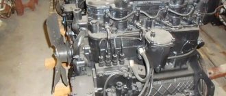
A41, removed from the DT-75 tractor:
Technical characteristics of the A 41 engine in the stock version:
- Engine weight A 41: 930 kg.
- Motor dimensions: length 1425 mm, width 827 mm.
- Cylinder block design: cast iron BC.
- Fuel supply: direct diesel injection method.
- Cylinder operation algorithm: 1 – 3 – 4 – 2, counting is carried out from the engine fan.
- Volume: 7.43 liters.
- Developed power: up to 90 horsepower.
- Number of revolutions according to the passport: 1750 rpm. in a minute.
- Cylinders: 4.
- Cylinder arrangement: mounted vertically.
- Piston stroke length: 140 mm.
- Individual cylinder diameter: 130 mm.
- Standard compression ratio A41: 16.
- Developed torque: 412 Nm at 1300 rpm.
- Fuel consumption: min. 1.62 kWh.
- Cooling system of diesel engine A 41: liquid.
- Oil used: DS-11 in summer, DS-8 in winter.
- Motor generator: DC unit 7=G304, 214A1.
- Number of timing valves: 2
- Hydraulic pumps: 2 gear pumps, driven from the crankshaft by a gear-type transmission.
- Declared engine life: 12 thousand hours on the latest engine models.
Review and features - A-41 engine
The 90-horsepower engine has a respectable cylinder capacity of 7.43 liters, which allows the base A 41 model to produce such power at relatively low speeds, about 1750. Following engine building trends, the developers introduced an electronic direct injection system into the A 41 engine: fuel supply is fully controlled electronics.
An important feature of the A 41 engine is its two-valve gas distribution mechanism. Engineers used it to give the engine the highest possible efficiency, output and efficiency.
To make the unit more reliable, the A 41 uses high-strength cast iron liners, the surface of which is treated by top honing. This increases the life of the motor, coupled with a well-thought-out cooling system (although the weight also increases). As such, an external oil-liquid heat exchanger is used, which cools the engine equally well both in idle mode and at maximum loads. By maintaining a stable, comfortable operating temperature, engine reliability has been further improved.
Checking for correct installation
After setting the angle is completed, it is necessary to check:
- Warm up the power unit to operating temperature and drive onto a flat, straight section of the highway.
- Accelerate with gear shifts up to a speed of 50 km/h.
- Stabilize the movement, and then sharply press the throttle pedal.
If the settings are correct, a brief knock will appear, indicating detonation combustion of the mixture. The absence of sound indicates a delay in the pulses, and prolonged detonation indicates an early spark. In this case, it is necessary to make additional adjustments and recheck the result.
Specifications
A 41 is a series of four-cylinder naturally aspirated diesel engines. Their main purpose is use in construction equipment and agricultural machines. A 41 is a high-quality, unpretentious, durable unit, easy to operate and has good maintainability, and this characteristic of A 41 engines has allowed it to gain consumer recognition.
A41, removed from the DT-75 tractor:
Technical characteristics of the A 41 engine in the stock version:
- Engine weight A 41: 930 kg.
- Motor dimensions: length 1425 mm, width 827 mm.
- Cylinder block design: cast iron BC.
- Fuel supply: direct diesel injection method.
- Cylinder operation algorithm: 1 – 3 – 4 – 2, counting is carried out from the engine fan.
- Volume: 7.43 liters.
- Developed power: up to 90 horsepower.
- Number of revolutions according to the passport: 1750 rpm. in a minute.
- Cylinders: 4.
- Cylinder arrangement: mounted vertically.
- Piston stroke length: 140 mm.
- Individual cylinder diameter: 130 mm.
- Standard compression ratio A41: 16.
- Developed torque: 412 Nm at 1300 rpm.
- Fuel consumption: min. 1.62 kWh.
- Cooling system of diesel engine A 41: liquid.
- Oil used: DS-11 in summer, DS-8 in winter.
- Motor generator: DC unit 7=G304, 214A1.
- Number of timing valves: 2
- Hydraulic pumps: 2 gear pumps, driven from the crankshaft by a gear-type transmission.
- Declared engine life: 12 thousand hours on the latest engine models.