The GAZ 66 gearbox is four-speed, with synchronizer in 3rd-4th gears.
Gear ratios: in first gear 6.55; on the second 3.09; on the third 1.71; on the fourth 1.0; in reverse gear 7.77. The gearbox is attached to the clutch housing with studs. Main parts of the box
: crankcase with cover, input shaft with gear and bearings, intermediate shaft with gears and bearings, secondary shaft with gears and bearings, synchronizer, reverse gear block with axle, gear shift mechanism.
The cast-iron crankcase is closed with a lid on top, and has hatches in the side walls for connecting the power take-off;
in its absence, the hatches are closed with lids. On the left wall of the crankcase there is a control and filler plug, and at the bottom there is a plug for draining the oil. A dirt trap is installed at the bottom of the crankcase, and a breather is installed in the rear bearing cover of the secondary shaft. The input shaft is manufactured integrally with the gear and the front end rests on a ball bearing installed in the crankshaft bore. The front support of the secondary shaft is a roller bearing installed in the bore of the primary shaft. The inner rings of ball bearings are secured to the shafts with nuts, and the outer rings are secured with split thrust rings clamped between the bearing caps and the crankcase. The intermediate shaft is manufactured integrally with its gears. The first gear and reverse gear are installed on the splines of the secondary shaft; The gears of the second 11
and third
21
gears of this shaft are installed freely, bronze bushings are pressed into their holes. The second gear gear has a toothed ring on the hub, and the third gear gear also has a cone.
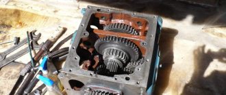
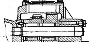
Gearbox structure of a GAZ-66 car:
1 - crankcase; 2 — intermediate shaft drive gear; 3 - intermediate shaft; 4 — input shaft gear; 5 - secondary shaft; 6 - input shaft; 7 — synchronizer; 8 — crankcase cover; 9 — shift rod for first and second gears; 10 — clamp; 11, 20 — second gear gears; 12 — lever; 13 — shift rod for third and fourth gears; 14, 19 — first gear gears; 15 — reverse gear engagement rod; 16 — breather; 17 — reverse gear block; 18 — axis of the reverse gear block; 21, 22—third gear gears; 23— drain plug; 24 — control filler plug; 25 — plunger of the locking device; 26 - pin; 27 - fuse against accidental engagement of reverse gear. The secondary shaft is sealed with a rubber seal; oil leakage from the crankcase at the exit point of the primary shaft is prevented by an internal oil drain groove made in the bearing cover. The reverse gear block rotates on an axis pressed into the rear wall and crankcase boss. There is a bronze bushing in the hole of the block.
GAZ-66 gearbox synchronizer
: 1 - locking rings;
2 - crackers; 3 - hub; 4 - coupling; 5—wire ring: 6—fork; 7 - driven shaft of the gearbox The gears of the block, as well as the first gear and reverse gears are spur-cut, all other gears of the box are helical. The synchronizer serves for silent gear shifting by equalizing the angular velocities of the engaged elements. The box in question has an inertial synchronizer with locking rings. It consists of a hub, a coupling, two locking rings, three nuts, two wire rings. The hub is installed on the splines of the secondary shaft and secured with a nut. The hub has external teeth and grooves for crackers. The coupling is located on the teeth of the hub and is held in the middle position by crackers, the projections of which fit into the inner annular groove of the coupling. The crackers are pressed against the coupling by elastic rings. Bronze locking rings have outer teeth with bevels and cavities for crackers; The width of the depressions is slightly greater than the width of the crackers. The synchronizer works as follows. When the clutch moves, the force is transmitted through the cotters to one of the locking rings, which, together with the clutch, moves relative to the hub towards the engaged gear until it comes into contact with its conical surface. Due to the difference in angular speeds of the engaged gear and the driven shaft, a friction force arises on the conical surfaces, which rotates the locking ring until it stops in the cracks. In this case, the teeth of the locking ring will become opposite the teeth of the coupling and further movement of the coupling becomes impossible. After the angular velocities of the gear and synchronizer are equalized, the force that displaced the locking ring disappears; under the action of the driver, it will return to its original position, which is facilitated by the bevels on the teeth of the clutch and ring. After this, the clutch passes freely between the teeth of the locking ring and connects with the teeth of the small ring of the engaged gear. The gear is engaged silently. The gear shift mechanism is located in the box cover and consists of a lever, three rods with forks, three clamps, a locking device and a safety device against accidental reverse gear. Clamps prevent the possibility of spontaneous inclusion or disengagement of gears. The locking device does not allow two or more gears to be engaged at the same time. This device is located in the channel between the rods and consists of two plungers and a pin. The plungers are located in the wells of the rods, and the pin is in the hole in the middle rod. When the outermost rod moves, the plunger leaves its well, enters the well of the middle rod and moves another plunger through the pin into the well of the second outer rod. Thus, the middle and second outer rods are in a locked position. When the middle rod moves, both plungers come out of its holes and enter the holes of the outer rods, locking them. When engaging reverse gear, the driver additionally overcomes the resistance of the fuse spring, which prevents the possibility of accidentally engaging reverse gear when moving forward. Gearbox operation. When engaging first gear, the driver moves the upper end of the lever toward himself and forward, while the lower end of the lever enters the adjusting head of the first gear rod and moves it backward. This movement is transmitted through the fork to the gear, which, moving along the shaft splines, engages with the first gear gear of the intermediate shaft. Torque is transmitted through a pair of gears to the intermediate shaft and through a pair of first gears to the output shaft. In both pairs of gears, the torque increases and the rotation speed decreases. In second gear, the gear moves forward and, with its internal teeth, connects to the small ring gear of the gear. Torque is transmitted through pairs of gears and through the gear hub to the output shaft. In third gear, the driver moves the synchronizer clutch back. After aligning the angular speed of the gear with the angular speed of the secondary shaft, the synchronizer connects the gear to the shaft. Torque is transmitted through pairs of gears and a synchronizer to the secondary shaft. In fourth gear, the primary and secondary shafts are connected to each other using a synchronizer; torque is transmitted from one shaft to the other directly, without change. In reverse gear, the driver moves the reverse gear unit forward, its front gear is connected to the first gear of the secondary shaft, and the rear gear is connected to the first gear of the countershaft. Torque is transmitted through gears 2 and 4 to the intermediate shaft, through the gear to the front gear of the block and from the rear gear of the block to the output shaft gear. In this case, three pairs of gears are involved, the primary and secondary shafts rotate in different directions. The rubbing surfaces of the box are lubricated by splashing the rotating gears with oil poured into the crankcase. The gearbox is filled with 3.5 liters (with a power take-off 4.2 liters) of oil
. On the GAZ-53A, the gearbox is the same as on the GAZ-66. The difference is that the speedometer drive is installed in the rear bearing cap of the output shaft, and the gear shift lever has a different shape.
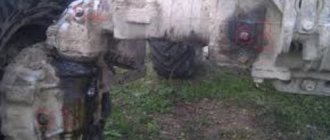
Removing the gearbox from a GAZ-66 car
Removing the gearbox and power take-off from a GAZ-66 and GAZ-66-02 vehicle must be performed in the following sequence:
1
.
Raise the cabin. 2
.
Unscrew the bolts securing the cab cross member (on the left along the vehicle) to the frame. 3
.
Disconnect the manual throttle control rod from the lever. 4
.
Disconnect the choke control rod from the carburetor. 5
.
Disconnect the brake control cable from the blind drive lever. 6
.
Disconnect the blind control cable from the frame. 7
.
Loosen the bracket securing the left fuel tank fuel line from the cab cross member and release the fuel line. 8
.
Disconnect the starting heater wires from the heater motor, solenoid valve and heater spark plug. 9
.
Disconnect the vertical link of the hand brake from the lever. 10
.
Remove the transfer case lever handles. eleven
.
Disconnect the power system pipes from the fuel tank switch valve. 12
.
Remove the faucet protective shield. 13
.
Disconnect the hydraulic brake booster shut-off valve from the floor. 14
.
Loosen the bracket securing the left fuel tank fuel line from the cab cross member and release the fuel line. 15
.
Remove the cover of the starting heater control panel. Disconnect the wire from the push-button fuse for the starting heater. 16
.
Disconnect the wire terminal from the ground switch. 17
.
Disconnect the rubber tube from the hydraulic brake booster breather. 18
.
Disconnect the pipeline from the tire pressure control valve. 19
.
Remove the power take-off lever handle. 20
.
Remove the gear lever protective cap and remove the lever. 21
.
Disconnect the front end of the intermediate driveshaft. 22
.
Remove the floor along with the cab cross member. 23
.
Remove the transfer case lever mounting bracket. 24
.
Remove the clutch fork spring. 25
.
Unscrew the clutch release bearing oiler. 26
.
Remove the clutch housing ventilation cover. 27
.
Remove the clutch fork. 28
. Remove the gearbox with power take-off.
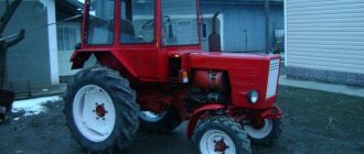
External tuning
Not all Soviet SUV bodies have retained their original appearance, so many cars already require welding and painting work. Not all owners of 66s are interested in painting them in their “native” color, and many owners try to make the car bright and different from others. It has now become fashionable to repaint off-road vehicles in camouflage colors. But still, the army color “khaki” also looks good - more solid and strict.
After the body has been brought into proper shape, it is additionally worth doing anti-corrosion treatment.
Modification of the Gas 66 truck for off-road travel
There is no point in installing any reinforced bumpers or additional thresholds - the GAZ 66 does not need additional body protection.
His original front bumper is already powerful enough, but a winch on the bumper wouldn’t hurt at all. It is worth thinking about tuning external lighting. Standard headlights will dimly illuminate the road at night in the forest or on a country road, so it makes sense to install additional optics. Nowadays, LED lights and headlights are often used as additional light. This optics has its advantages:
- LED lights are very economical and do not overload the vehicle's electrical circuit;
- The LEDs themselves are very reliable and have a long service life;
- These headlights have a fairly robust design.
Additional light is installed on the SUV front and rear. With additional rear lighting it is convenient to turn around somewhere on a bad road in a dark forest. At the front, headlights are mounted at different heights; generally, headlights are mounted on the bumper or on the roof of the car.
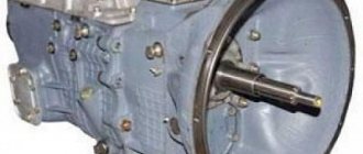
Dismantling the GAZ 66 gearbox
Removing the central brake. 1
.
Remove the top cover assembly. 2
.
Remove the assembled clutch with the central brake drum from the driven shaft. 3
.
Remove the drum from the coupling. 4
.
Remove in sequence: oil deflector, oil deflector gasket, central brake assembly, central brake disc deflector. 5
. Remove the lever from the central brake drive lever pin. Remove the fitting and the driven speedometer drive gear from the rear cover, then unscrew the breather.
6
.
Remove the rear cover and the speedometer drive gear. 7
.
Remove the drive shaft cover. 8
.
Turn the drive shaft so that the semicircular recess on its spur crown and on the cone is at the bottom, then remove the assembled drive shaft from the crankcase (Fig. 2) 9
.
Remove the ball bearing retaining ring. 10
.
Remove the gasket and power take-off hatch cover. eleven
. Remove the countershaft rear cover and reverse axle thrust plate.
12
.
Remove the ball bearing of the intermediate shaft by first sliding the shaft out of the crankcase (Fig. 3 and 4). 13
.
Remove the intermediate shaft and inner ring assembly from the crankcase. Remove the roller bearing inner race from the intermediate shaft. 14
.
Remove the outer ring of the intermediate shaft roller bearing from the crankcase. When disassembling and assembling the gearbox, it should be noted that the outer and inner rings of this bearing are not interchangeable. Therefore, if it is necessary to replace one of the rings, the entire bearing must be replaced. 15
.
Remove the reverse gear block axle. 16
.
Remove the reverse gear block from the housing. 17
.
Remove the front intermediate shaft bearing plug. 18
.
Remove the dirt trap from the crankcase. Dismantling the drive shaft.
Remove the retaining ring, thrust washer and rollers of the front driven shaft bearing.
On some vehicles, the retaining ring and thrust washer are not installed. The rollers of the front bearing of the driven shaft are not interchangeable. They are sorted into groups every 0.005 mm and placed in a unit as a complete set of only one group, so when one or more rollers wear out, the entire set must be replaced. Unscrew and unscrew the ball bearing mounting nut and remove the bearing. Dismantling the driven shaft.
1
.
Unscrew and unscrew the synchronizer hub mounting nut. 2
.
Remove the hub and synchronizer sliding sleeve (Fig. 5). 3
.
Remove the nuts and synchronizer springs. 4
. Remove in sequence: synchronizer blocking ring, third gear, spacer sleeve, thrust washer, second gear.
Dismantling the upper gearbox cover
1
.
Remove the plug from the hole under the locking plunger. 2
.
Remove two pins from the neck of the lid. 3
.
Remove the conical spring. 4
.
Knock out the stoppers from the shift fork and the transfer head of the first and second gear rods. 5
.
Remove the fork and shift head from the shift rod for first and second gears and remove the rod. 6
.
Knock out the third and fourth gear shift fork stopper. 7
.
Remove the third and fourth gear shift fork from the rod, remove the rod and remove the locking pin from it. 8
.
Knock out the locking pins from the fork and reverse gear. Remove the fork and shift head assembly from the reverse shift rod and remove the rod. 9
.
Remove the locking springs, plungers and rod lock balls from the holes in the cover. Disassembling the transfer head of the reverse rod. Unscrew and unscrew the spring stopper. Remove the spring and fuse.
Replacing the power unit
No matter what remarkable characteristics the GAZ 66 has, by modern standards the car only meets the requirements for cross-country ability. The engine produced by ZMZ is no longer considered powerful enough, much less economical.
Usually the factory engine is replaced with a D-245 diesel engine (manufactured by Minsk Motor Plant) or with a 4.5 liter ISUZU engine.
Many enterprises install diesel engines from the Minsk Motor Plant. Companies often offer replacement of the standard 66 engine with a turnkey MMZ D-245. That is, the owner of a GAZ 66 only needs to take his SUV to the company’s service center, and after a certain period of time receive a car with a new engine. Of course, the motor itself and the work performed are guaranteed.
The process of installing a diesel engine on a GAZ 66
ATTENTION!
The electronic catalog of spare parts intended for reference purposes only!
Our company does not sell all spare parts presented in this list. If there is a “Cost” link in the right column, these spare parts are on active sale. Availability in warehouses for details and prices, see the product card. If there is no “Cost” link in the right column, we do not sell such parts and do not accept orders for them.
Description and principle of operation of the distributor
The transfer case is similar to the transmission box in terms of both appearance and functionality. Its main purpose is to distribute loads evenly across all bridges. Depending on the type of vehicle, the transfer case can be connected only to the front axle or also to a low gear.
The operating principle is as follows:
- When the clutch is engaged, torque is transmitted to the transfer case drive shaft and then to the rear wheels. This is ensured by the meshing of the carriage gear with the corresponding gears.
- If there is no engagement, then torque will not be transmitted to the wheels.
- Also, the engagement of the carriage gear with the proper gear ensures that the downshift is engaged. Used when driving on sticky soil or uphill under load. As a result, traction forces on the wheels increase and cross-country ability increases. This only works in all-wheel drive to avoid overloading the rear axle drive.
The transfer case helps distribute the load evenly
Transfer case service
The box is subjected to severe stress during operation. Its serviceability depends on compliance with the rules of use and constant prevention.
The main symptoms of a faulty mechanism:
- Additional noise and vibration.
- Difficulty turning control levers on or off.
- Spontaneous shutdown of the mode on the go.
- Oil stains on the body, oil leakage.
To detect them in time, it is necessary to regularly:
- Visual inspection of the box.
- Adding oil to the crankcase.
- Checking and correcting fastening tightening.
These simple steps will not take much time, but will allow you to detect the first signs of malfunctions and eliminate them in a timely manner.
The main causes of problems and ways to fix them:
- Insufficient oil level in the crankcase or its quality is inadequate. You need to regularly check the oil level and top up if necessary. Buy lubricants only from trusted suppliers.
- Wear of teeth of drive mechanisms. Minor damage is eliminated by grinding, large damage by replacing parts.
- Faulty fork attachment or worn out connecting rods.
- Broken clutch module. In this and the above cases, failed parts must be replaced.
- Wear of gaskets and seals. These parts need to be changed in a timely manner, since their service life is short. You should always have a supply of consumables and lubricants.
The transfer case and gearbox of the GAZ 66 are quite complex so that repairs can be carried out without proper experience. If you don’t have experience in DIY repairs and don’t have the necessary tools, it’s better to contact a car service center. However, if you have experience successfully working with truck components, you can begin repairs by first studying the instructions and watching training videos.
Device
There are a huge number of drawings and photographs on the Internet, from which the transfer case and the GAZ 66 gearbox diagram can be studied in detail. There are also videos on disassembly, repair and assembly that allow you to look at all the details.
Main elements of the GAZ-66 box:
- Carter. Made from cast iron by welding. Filled with transmission oil. A mechanism for shifting gears and engaging the front drive axle is installed on the cover.
- Drive shaft. It is located in the crankcase and connected to the gearbox output shaft. It has splines on which a gear-carriage is installed, which ensures engagement of the rear axle and downshift.
- Rear axle shaft. It has a gear that meshes with the carriage gear.
- An intermediate shaft that transmits torque to the front axle.
The transfer case has gear ratios of 1.98 and 1, respectively for low and direct transmission. At the same time, the gear ratios of the GAZ 66 gearbox are made in increments of 14.7.
This is a description of a transfer case for a two-axle vehicle. The transfer case for the three-axle version has two positions for the downshift lever, which ensures automatic engagement of the front axle when downshifting.
The transfer case can have several operating modes:
- only the rear axle is connected;
- two drive axles are connected;
- two axles are connected with inter-axle locking;
- connection of both axles with low gear and inter-axle locking;
- connection of both axles with automatic differential locking.