One of the popular ways to make a homemade electric winch is to use a car starter. This device is equipped with a powerful high-torque electric motor with a supply voltage of 12 volts, which allows the winch to be used on an SUV.
When manufacturing, you should remember the limitations:
- The starter is designed for short-term operation. This does not mean that it will immediately burn out under prolonged load, but the motor housing does not provide sufficient winding cooling. If you plan to use the winch regularly and the work periods will be long, you should take care of additional cooling. For example, weld aluminum corners onto the body as cooling fins;
- The car starter is started using a retractor relay with a bendix. You don't need a solenoid for the winch, but a contact starter wouldn't hurt. The current at the contacts will be large, and it is better to leave the standard switching circuit. Depending on the gearbox used, the bendix should be fixed by welding in the position of maximum engagement or removed from the solenoid relay;
How to make a winch from a starter
Let's take the Zhiguli starter as the initial donor. It is quite reliable and at the same time has a compact size. Another advantage of this choice is that a VAZ starter can be found almost for free at any dismantling of domestic cars.
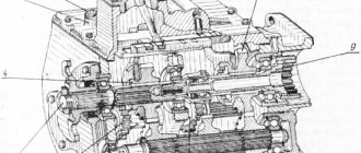
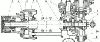
The drawing shows the device and components of the starter. In the upper part there is a retractor relay with power contacts. They can be used if large loads on the winch are expected. On the left is the bendix mechanism, which must be removed along with the cone housing.
Since we are talking about a compact, low-power mechanism, it makes no sense to make a gearbox for a winch from a flywheel gear. It is enough to pick up a unit from a large drill. Finding one will also not be difficult, since there are more tools with a burnt out motor at flea markets than with a broken gearbox.
There are no special requirements for the gearbox, the main thing is that the diameters are more or less suitable.
For our adaptation, of course, we need to reduce the speed.
We separate the Bendix housing from the winch, and we are left with only an electric motor with a rotor shaft. The coupling of the gearbox shaft with the mating part of the starter motor is done locally. There are many ways - from banal electric welding to making a transition coupling with cotter pins.
If it is necessary to increase the gear ratio, you can use a starter with a planetary gearbox. Adapting it to your design is not much more difficult than connecting the shafts directly, and the useful power of the winch will increase significantly.
To protect the operator from rotating parts, the space between the gearbox and the engine is closed with a pipe of a suitable size, possibly made of plastic. The casing does not carry a power load, so the gearbox housing must be firmly connected to the motor housing.
Simple threaded studs will not work here; you need to work on the design. In this case, the housing must be dismountable for periodic inspection and maintenance (cleaning, lubrication) of the motor bearings and gearbox mechanism.
Next we make the drum. You can make it at home from a piece of steel pipe with a diameter of 120-180 mm and sheet iron 2-3 mm thick.
We cut out round cheeks and weld them to the pipe. In the center of each sidewall we drill a hole for the power shaft.
The power shaft with the working gear in this design is borrowed from a decommissioned electrified valve mechanism, which is used on gas and oil pipelines. Be sure to use a standard pair of gears, otherwise it will be difficult to pair the main sprocket with the gearbox output.
All elements must be securely welded together; any weakness will sooner or later crack, and the structure will fall apart at the most crucial moment.
A channel or steel strip with a thickness of at least 5 mm is used as a frame. The winch elements should not have any play relative to each other.
The side walls are made of sheet iron 3-5 mm. Thinner sheets may become deformed when the cable is pulled under load.
The most important part is attaching the drum axis. For this, powerful bearings with podiums from some mechanism from the times of the USSR were used. You can find such spare parts at scrap metal collection points or in the workshops of abandoned factories.
The podiums are welded to the side walls. If you managed to find only bearings, weld the outer race. Nothing will happen to the rolling mechanism; the bearings simply cannot be replaced.
We attach the gearbox to the frame so that its gear meshes with the power gear on the drum shaft. We remind you that initially we had a set of a shaft and a set of gears. We install an eyelet between the walls - a leash for the cable.
We connect the gearbox with the electric motor from the starter, put the winch in good shape: we clean the welds with a grinder, remove rust, and cover the tool with paint.
The design has been tested to lift weights up to 200 kg. In this version, two gearboxes are used - from an electric drill and a homemade one from a gas electric valve. It feels like there will be enough traction for another 100-150kg.
If you install a starter with its own planetary gearbox, the gear ratio of which will be added to the two existing ones, the capabilities of the device will double.
The video shows an example of a winch using a starter.
How to use the device?
Be sure to provide for the possibility of reversing the power supply to the winch. Reverse is necessary in such devices. Since this is a regular car electric motor, changing “+” to “-” will change the direction of rotation of the shaft.
Let the power starter be the old one, from the solenoid relay. And the start buttons come from ancient electromechanical devices. The button block can provide for polarity reversal.
If the winch is used in a car, do not connect it to the standard battery with the engine turned off. With a good load, you will drain the battery in 10-15 minutes.
The dimensions allow the winch to be placed on the bumper of an SUV prepared for off-road use.
Homemade reduction gearbox for a mini tractor, its assembly
The design of a mini tractor is a mechanism that must be designed so that it can cope with a number of tasks such as cultivating soil, clearing terrain, harvesting grass, etc.
In particular, for plowing the land, the speed reserve is very important, as well as the power of the unit, and therefore a necessary element of the circuit is the gearbox. It is located between the gearbox and the clutch parts and consists of gears that mesh with each other. The type of factory or home-made reduction gearbox for a mini tractor depends on its operating efficiency, as well as its ability to overcome difficult terrain conditions, so you need to be very careful when choosing a model and installing it.
Features of the gearbox and its influence on the design of the mini tractor
In most cases, a minitractor that was not assembled at the factory, but independently, is equipped with a gearbox from suitable equipment (walk-behind tractor, motorcycle) or is also made by hand. If you take a ready-made part, then you only need to take into account the correct gear ratios and install it; the second option is more difficult. As a rule, in order to make a homemade gearbox for a mini tractor, a ready-made housing is taken: it is not possible to make it yourself, since in the factory it is made from cast iron or alloys containing aluminum using special equipment. Shafts and gears should be selected taking into account the load on the finished spare part, and bearings, seals and fuses should be selected according to the design.
Reducing gearbox for a mini tractor: possible breakdowns
As a rule, if used incorrectly or worked in difficult conditions, this part may fail for the following reasons:
- Excessive physical stress, as a result of which shafts and gears can overheat in spare parts, and gear teeth can break. In the latter case, the breakdown can be diagnosed due to characteristic shocks in the chassis area and the inability to reduce the speed to the desired level.
- Improper care or lack thereof. Inspection of a mini tractor also includes checking the main parts related to the wheelbase and engine, so gearbox faults will be detected fairly quickly.
- Incorrect selection of consumables: lubricants, etc.
Assembly of a reduction gearbox: what needs to be taken into account?
When designing a homemade reverse gearbox for a mini tractor, you should first take into account a number of details:
- The rated power required by the device.
- Torque.
- Gearbox installation angle.
- Number of revolutions per minute.
- Load on the shafts of the spare part along the axis and radius.
- Limits of temperature arising during operation.
- Type of lubricant required.
- Switching cycle (full or variable).
conclusions
In a homemade mini tractor, controllability is very important, which is directly affected by the number of speeds and the ability of the mechanism to switch between them.
The ability to sharply reduce speed to a minimum and increase power is the task of a reduction gearbox, and its installation is mandatory if the minitractor is intended for cultivating soil or removing loose and hard materials from the surface (for example, removing snow, leaves, grass, etc.).
When installing this part, it is important to calculate the load on it and the capabilities of the tractor after that, since an incorrectly selected or incorrectly installed gearbox will not allow the machine to develop its capabilities to the fullest.
Video
The operation of a homemade reverse gearbox is shown in the video.
Do-it-yourself winch - price
If you have your own garage or shed with rubbish accumulated over several years of home plumbing, the cost of the product is determined by the price of a can of spray paint for final finishing.
Basically, the components are as follows:
- Starter from a VAZ 2101 car without a planetary gearbox (working, lying in the garage);
- A gearbox in a housing from a domestically produced electric drill (purchased at a flea market for the equivalent of 0.5 vodka);
- A piece of water pipe found in a barn;
- Metal for the frame, body walls, drum. Also found in a barn;
- Drum axle - purchased at a scrap metal collection point for pennies;
- The rope and hook were purchased at a tourism supply store.
Taking into account the cost of a new winch, the cost of the issue can be considered zero. At the same time, the owner can vouch for the safety of the device. Every detail and weld is personally checked by the manufacturer.
Source: obinstrumente.ru
How to install a reverse box on a motorized dog
How to do reverse (reverse gear). on a motorized towing vehicle?
There are manufacturers who have provided the possibility of installing reverse after purchasing a motorized towing vehicle.
For example, the BTS brand. A client, purchasing the simplest basic motorized towing vehicle from this brand, can subsequently, for example, after a year, install a reverse box and brake on his towing vehicle, if necessary.
If the client, during operation, realized that it is difficult for him to live without a reverse box, that he needs reverse gear, he can come to the manufacturer or dealer or simply call them and buy a reverse box. The manufacturer will provide it with all the necessary components.
To install reverse, the standard transmission is disassembled and a reverse box is installed instead. This is not problematic, since the manufacturer provides a video that describes in detail the installation of the reverse box from scratch. Reverse installation can be done at home.
There are manufacturers who produce towing vehicles only with a reverse gearbox.
There are manufacturers who make towing vehicles without a reverse box and without the possibility of installing a reverse box later, since the frame of the towing vehicle is not designed for installing a reverse box at home.
When purchasing a motorized towing vehicle, pay attention to whether additional options can be installed on it after purchase..
How much does reverse cost?
It all depends on the manufacturer who installs it. Now 90 percent of the market uses a reverse gearbox from Buran. It has been slightly modified to serve as a motorized towing vehicle, and that’s what everyone uses. What are its advantages?
The box has been installed on snowmobiles for 50 years, it has already been improved, people know it like the back of their hand.
Another big plus is that any part, any spare part can be replaced by purchasing it in a store that specializes in selling spare parts for Russian snowmobiles.
Everything there remains Buranovsky, except that the shaft changes and that’s it. But nothing can happen to the shaft, it walks for a long time, it won’t be broken.
Availability of spare parts is an important factor when purchasing, when choosing a reverse box or a towing vehicle with a reverse box, because someone installs Chinese reverses and will have to look for this reverse later if something breaks in it.
A man bought a towing vehicle with a reverse gearbox, drove it, and it broke. He needs a towing vehicle to drive. He doesn’t have time to repair the box; it’s good if he can at least remove it, install a standard transmission and continue driving quietly.
In some towing vehicles, everything is so connected that if the box breaks, the towing vehicle will not go anywhere until it is fixed. This is important to know.
Why reverse gear on a motorized towing vehicle?
Reverse gear is very convenient. We don't drive on smooth roads. We drive through the forest, through virgin lands, fields, ravines, potholes.
It happens that a person overdosed on gas, buried himself, ran into branches or some bush, or fell into a ravine, and there is no way forward.
But digging and carrying it on yourself is hard and you get tired, but here you can turn on the reverse gear and calmly drive back and make a new road for yourself, or just back up and go a different way.
Different manufacturers have different ways of switching the reverse gearbox. Some manufacturers install the reverse gear shift lever on the towing vehicle itself. These are, for example, Burlak, Veps, Stem and others. Baltmotors, in my opinion, has already done it on the lever, on the steering wheel, BTS does it on the steering wheel. The cable is installed, the switch itself is on the steering wheel.
We don't have to get off the sled to engage reverse gear. We turn it on while sitting in the sleigh, and it is very convenient. Sometimes you drive into waist-deep snow, and to engage reverse gear you have to get off the towing vehicle.
At the same time, we fall into the snow up to our waists, start digging around there, put the gear in reverse, climb onto the sled, back up, again jump into this pool of snow, swim to the towing vehicle, shift gears and swim back to go forward.
It seems like you bought a product that costs between 15 and 20 thousand rubles, paid extra for this option, but you have to jump into deep snow to change gear and this is a huge minus. If there is comfort in the reverse gearbox, there should be comfort in switching the reverse gearbox.
How to service the reverse box?
The reverse box needs to be serviced. The box needs lubrication, like any gearbox in any vehicle. Here it is much easier to change the lubricant, here everything is simplified in the reverse gearbox itself, if we are talking about the Buranovskaya gearbox, and we are talking about it because 90 percent of manufacturers install it and it is the most popular. Only 300-350 grams of oil are poured there.
The oil is changed along with the engine oil. You can pour some kind of transmission oil in there, but, as a rule, everyone pours the same oil in there as in the engine. In general, this does not harm her in any way. There is not much oil there, the most important thing is that there is an oil bath in which the chain is constantly lubricated.
Pumping out the oil is quite simple: take a pharmaceutical syringe, put on a six-piece hose from the dropper, pump out the old oil, pour in fresh oil through the filler plug. All.
We change it once a season if the motorized towing vehicle has been run-in. We change it once a season at the beginning of the season, before leaving. It's simple. Oil is inexpensive.
Source: https://xn--80affbpmqdh0ap1b.xn--p1ai/blog/kak-ustanovit-korobku-reversa-na-motosobake.html
Self-assembly of a reversible gearbox from the gears of old Zhiguli cars
A reverse gearbox is a device that allows you to reduce the speed of modern air-cooled diesel or gasoline vehicles. It is also needed on a walk-behind tractor, where it helps increase power and extend the service life of the unit.
The gearbox can be taken from another device, or you can make it yourself from gears, for example, from an old Zhiguli car. At the same time, it must have a sufficient margin of strength and power to work in various areas.
Dependence of the mini tractor operation on the gearbox
The walk-behind tractor is designed to facilitate the work of landowners. In order for it to work properly and flawlessly, plowing the ground, removing leaves and dry grass, and planting, it is necessary to have a sufficient supply of power and speed. To find out how to reverse on a walk-behind tractor, you need to familiarize yourself with its structure and the tasks assigned to it.
The lowering reversible unit is called a creeper. They are equipped with all modern installations that run on gasoline or diesel and are air-cooled. This addition allows the agricultural machine to operate safely under increased load, such as digging up potatoes, cultivating heavy soil, and plowing. With the help of this reduction unit, it becomes possible to increase power and eliminate wheel pair slipping.
You need to choose power depending on the size of the area:
- 5 hp — from 6 to 10 acres;
- 6 hp - no more than 30 acres;
- 7 hp - up to 50 acres;
For larger plots, a power exceeding 7 hp is selected. The installation diagram includes a gearbox for a mini tractor; it is mounted on the drive shaft, where there is a gearbox on one side and a clutch assembly on the other. It is represented by gears that mesh using a gear train. The reversible gearbox provides a set of required speeds. If you decide to make it yourself, then it must be reliable and withstand loads in difficult areas.
You can simply borrow this unit from another device - a motorcycle or mini tractor. It is important to take into account gear ratios. The reverse gearbox on the walk-behind tractor has a ratio of 1:4.62. Compliance with these values guarantees normal operation of the unit: improved running and traction performance and unloading of the drive gearbox.
Another interesting article: What type of cutter should be used for a walk-behind tractor and a cultivator?
Manufacturing process
Assembling the gearbox begins with a cast iron or aluminum housing. It needs to be selected from the factory, since you cannot make the case yourself. The housing houses gears and axles that can withstand the necessary loads. As a basis for assembling a reversible gearbox, you can take a gearbox from an old VAZ-2107. The sprockets, rod, bushings and fork will have to be machined from metal. All parts undergo a hardening process.
To assemble a good gearbox, it is important to consider how the circuit for switching the direction of movement of the walk-behind tractor works:
- On the main shaft there is a drive sprocket, which transmits torque to the drive bevel gear.
- There are two driven gears, they are located on a splined shank. One of them begins to rotate. It engages with a spline on the main shaft and transmits movement to the wheels of the car or differential.
- There is a fork on the reverse rod. It is used to flip the bushing to the right, left or neutral. In this way, commands are given to change the direction of movement.
- The gearbox is controlled by a rod lever.
For a high-quality design of a reverse gearbox, you need to consider:
- Rotational speed;
- Rated power;
- Permissible heating temperature;
- Maximum loads on axles and parts;
- The angle at which the gearbox is located;
- The amount of torque;
- Option for lubrication of contacting parts;
- Frequency of work.
It is also important to operate the gearbox assembled in this way correctly, otherwise it may quickly break. The main reasons are too much load, leading to overheating of the shaft and parts, and breakage of teeth. An incorrectly selected gear ratio can also lead to breakdowns. Regular maintenance of the main components and mechanisms of the walk-behind tractor cannot be neglected.
A properly designed homemade reverse gearbox should ensure an increase in the power of the walk-behind tractor during a sharp drop in speed,
Source: izdoski.com
Manufacturing of a reversible gearbox
If you want to build a unit at your own discretion, then you cannot do without a borrowed housing. It is impossible to do it yourself outside of factory conditions. The material used is cast iron or aluminum alloy. The body is produced using special equipment. To make a reversible gearbox at home, you need to start with the housing. If it was not possible to select from other mechanisms, then it can be built from a gas pipe with thick walls with an outer diameter of 2.73 cm. Internal components: axles, gears. They must withstand the loads to which the homemade reverse gearbox will be subjected. Regarding seals, bearings, fuses, it is recommended to select them based on the design.
A homemade reverse unit can actually be assembled from the elements that make up the main gear on a used GAZ-69 car. Hubs, bushings for reverse, sprockets, rod, fork are machined from metal. 45 steel is suitable for this. Finished parts must be hardened. You should be very careful in the manufacture of cams on the hubs, as well as reversible bushings, since they will be subject to increased dynamic loads. The drive and driven gears must be isolated from each other by a gasket, the thickness of which can be adjusted to the degree of their pressing.
Homemade gearboxes, gearboxes, etc.
Questions can only be asked after registration. Please login or register.
I propose to collect homemade gearboxes, gearboxes, drive axles and the like in one place. Discuss methods for manufacturing parts and housings for them. TO THE EDITOR - if there is already a similar topic - please tell me.
here is my bevel gear. gears from the differential from the gear, the axle gear was tucked under the 25 mm shaft and the bushing was welded, the pinion gear was simply welded to the 20 mm shaft, everything else can be seen from the photographs, if you ask for a photo of cutting the splines post-on, I just wanted to show how I cut it with alignment, I didn’t bother
Remember: it’s better to lose a day, then fly to my channel in five minutes https://www.youtube.com/channel/UC1vTkviCAeiA9Z4yTOHM7uQ
Finally the Internet is working. I assembled it 2 years ago to connect the GAZ-51 gearbox and the M-412 bridge. The body is channel 14, gears are from the 51st gearbox (3rd gear, splines are welded into the drive gearbox for the output shaft of the GAZ-51 gearbox), and at the output of the gearbox there is a cut-off secondary shaft of the GAZ-51 gearbox.
Built a boring head.
I'll try to bore it for a homemade transfer case.
Built a boring head.
and what is the cutter itself made of? I thought for a long time about what I could make a reduction gear out of, and today it dawned on me, I found the crown of the launcher and the bendex starter, the gear ratio should be about 7.5 and the chain drive 2.3 in total 17.25, maybe it will be useful for someone, for example, for making a meat grinder.
Remember: it’s better to lose a day, then fly to my channel in five minutes https://www.youtube.com/channel/UC1vTkviCAeiA9Z4yTOHM7uQ
and what is the cutter itself made of?
A sharpened tap. Today I tried to sharpen it a little - it takes cleanly, now I just have time to choose a free time.
A cutter made from a tap is for small holes (up to 30 mm), for “larger” ones – soldered.
I put the transfer case aside for now - I don’t have much time, I’m making the same gearbox as before. The GAZ gears couldn’t withstand the uprooting of cherries in the fall. These should withstand it (the gearbox is from KPI, it feeds the mass into the chopper).
The computer did not send photos and then refused to turn on. It can’t work from the phone either. I'll try to install the gearbox tomorrow.
Not in order, but you can understand.
The gearbox is assembled, tested and working. Now a reverse gearbox suggests itself. If anyone has done this, tell me which gears it is made of.
The topic has died down, probably no one is interested in it. Winter has passed, but there was not enough time for the gearbox, now we have to hurry. In general terms: I used gears from the gearbox - Gas 52 and the oil pump drive gear from engine A - 41, the drive shaft from the primary ZAZ gearbox and the secondary gearbox Gas 52, housing - sheet 10 mm. Photo of preliminary assembly, the body is not finished yet.
The topic has died down, probably no one is interested in it. Z
Why isn’t it interesting, very much so, but I don’t understand where the reverse is?
I made one for myself, later I’ll make another one, but this time with access to the front, and I need to think about something with the reverse
The topic has died down, probably no one is interested in it. Z
Why isn’t it interesting, very much so, but I don’t understand where the reverse is?
The drive gear moves on splines, connecting to the driven gear directly or through a gap (double).
Explain, I don’t know how you set the diameter for the bearing on the head?
Explain, I don’t know how you set the diameter for the bearing on the head?
First I go through with a small drill (5-10 mm), then a few mm less than the required diameter (I couldn’t find more than 50 mm, so it took me a long time to bore to the required 80), and after the drill, 0.25 - 0.5 mm per pass with measurement after each pass. The head is homemade, it “plays” a little, you have to play it safe.
after the drill 0.25 - 0.5 mm per pass
Can I have a drawing (schematic) of the head, I’m interested in the cutter feed mechanism itself
, I’m interested in the cutter feed mechanism itself
so he even has a video here, a regular drilling machine and a cutter with an offset
I'm interested in the cutting mechanism itself
Yes, everything is quite primitive, the thread is m8x1, loosened the dovetail clamp, turned the screw, for example, 1/4 turn - the hole diameter changed by 0.5 mm. The accuracy is not high, but it is enough to seat the bearing.
thread m8x1, loosened the dovetail clamp, turned the screw, for example, 1/4 turn - the hole diameter changed by 0.5 mm.
wow primitive! I can't do this.
We also need a gearbox, from the engine to the clutch. The gears from the ZID gearbox (2nd gear) and the gear from the guitar lathe to the parasite came in handy. Still in the process.
Here is the result. The reduction is 2.91, the input is from the engine crankshaft through the “donut” from the VAZ, the output is the ZAZ flywheel.
Noting in this thread .. I’m also thinking about a gearbox .. a little history: having installed a diesel engine on a Zila, the speed of 60-65 at 2300 rpm was not enough. so that's what I'm getting at. I have thoughts about making a divider like on a Kamaz and putting it in front of a Zilov gearbox. train of thought: take the input shaft from the ZiL high-speed gearbox (there are such... but a large gap between 3rd and 4th gear is very difficult for the engine). I repeat: the input shaft is the secondary shaft from the same gearbox. an intermediate shaft with a constant mesh gear (high-speed) and a 5th gear driven and driven (the gear ratio is 0.85, I don’t remember exactly) using the method of welding, etc., connect the secondary shaft of my gearbox with the primary shaft of the original ZIL gearbox and hide it all in a 20mm metal housing, trick up the fork included and get something like this. https://www.sychaolida.com/upload/201301/1357828666.jpg
Cool stuff. Where did it come from, where can I see the details?
About 30 years ago, calculating a gearbox was my course project, but now I don’t remember anything. The plans are to build an all-wheel drive mini tractor with a classic layout; a gearbox is needed between the transfer case and the rear axle.
Has anyone dealt with homemade blocking? I want to do chemical research on the T-150.
To liven up the topic a little, I want to tell you about my gearbox, it was made to remove the PTO from the VAZ-21093 gearbox with a smooth decrease in speed, since I work at a large machine tool plant, there were no special problems with manufacturing, the body is made of sheet metal 6 mm thick , with two stages of reduction, the gears were taken from gear grinding machines, replacement gears for them come with a difference of one tooth, so I could choose absolutely any gear ratio, I settled on a general gear ratio of 1: 4.05, the holes for the bearings were made with a larger diameter than the bearings themselves, then the rings were machined and welded into the holes, then the bearings were pressed into both holes for alignment, holes were drilled for the studs connecting the two parts of the housing, two gears with the 5th gear shift fork were removed from the gearbox, a small gear was put on the gearbox input shaft gearbox, the intermediate shaft is made from the secondary shaft of the ZAZ gearbox, and the engagement synchronizer is also from it, the secondary (driven) shaft of the gearbox is made from the gear shaft from the UAZ transfer case, the original gear was cut off from it and the required one was welded,
Source: fermer.ru
Do-it-yourself reduction gearbox
Do-it-yourself homemade reduction reverse gearbox: detailed photos of the gearbox manufacturing.
This homemade product was made by Yuri Zhuravlev. Further from the words of the author.
The moment has come when it is necessary to make a reverse gearbox for a mini tractor. To use one handle to change the direction of movement of the mini tractor - back and forth. When moving forward, torque will be transmitted through the gears, and when moving backwards, through the chain.
I decided that a reverse gearbox would be more useful than just a gearbox. I took gears from the VAZ-2109 gearbox as a basis. These are the large final drive gear and the first speed gear. They match in teeth. I also used a synchronizer and a second gear gear assembled with needle bearings.
The secondary shaft of the VAZ gearbox was redone (having previously removed the hardening in the oven). The second gear gear was also loosened in the oven. Then he processed it on a lathe. Giving it a seat under an asterisk. I use a 17 tooth sprocket. I welded it to the gear, processed the weld seam and hardened it. The second sprocket will be 25 teeth. The gearbox will be shifted using a standard nine-wheel fork and a rod with a ball lock. The second shaft for the gearbox will be homemade and oil-hardened.
I made a secondary shaft for the reverse gearbox. Since it is not possible to make and then cut splines on the ends of the shaft, we had to make the shaft using factory splined ends. One tip was used from a segment of the VAZ axle. The second was from the secondary shaft of the Toyota Mark 2 automatic transmission. (but in principle you can use any). I machined a shaft with a diameter of 45mm. and length 170mm. I drilled a hole inside for spline ends. I made the ends of the rollers with a lock. I drilled holes on the shaft housing for welding. I pressed the rollers into the body. I checked the runout on the lathe. I welded the rollers and holes. Processed the welding seams. Cut from metal 15mm thick. square blanks for pancakes. Processed them. I pressed the pancakes onto the shaft. Brewed it. The roller was processed in the cones of the lathe. All that remains is to drill the holes and cut the threads. And the secondary shaft of the gearbox is ready. I also made an adapter flange for the axle and reverse gearbox from the front hub of a VAZ-2109. Then he was quenched in (oil).
I turned out the housings for the bearings. Next from corrugated tape 4 mm thick. I made the bottom plate. Drilled holes. I grabbed it by welding at several points of the body on the plate. Inserted the shafts. Everything is spinning. There is a thermal gap. Nothing sticks.
Next I started making the side wall. From the same iron I cut a strip 95mm wide. First I tried to bend this strip on my rolling machine. But nothing worked out. The machine does not bend such a thickness of metal (and even the corrugation). I had to use another method. I clamped a blank into a yew (it works as an anvil for me). And according to it, as if according to a template, he bent the strip. Next, I gave it the required shape and welded it on the stove. I used a semi-automatic welding machine (electric welding has a strong effect). Next I sanded the seams. To attach the second cover, I welded an internal busbar. There will be connecting bolts on it. Next I machined the second housings for the bearings. And cut out the lid. I figured out the parts for the case. The chain is a little loose. Not critical of course. But I want to install second-layer dampers.
At this stage: I redid the sprocket mounting (so that the bearing housing does not rest against the bolts). Now the mounting bolts are on the inside. Screwed in using thread sealant. I made holes on the cover for fastening. I also made three guides. But instead of just pins, I installed bolts. They fit tightly into the lid. And they will additionally press it against the body.
To mark the holes for the bolts, I had to make a marking gasket. To weld the bearing housings, it was necessary to maintain the spacer distance. Therefore, I inserted 1mm thick metal plates between the halves. Welded the bearing housings. Still, she felt a little sick from the welding. I had to level it. I cut a hole in the end of the housing for the switching mechanism. The fork and synchronizer are used from the VAZ-2109 gearbox. For the fork rod, we had to machine the body in the form of a bushing. Inner diameter 14mm, outer 22mm. Length 120mm. I drilled a hole in the gearbox housing for the bushing. I welded it. After cooling, I cut off the inner part (to accommodate the fork). I also machined out a sleeve for the ball and springs for fixing the rod. I welded it to the rod bushing. Then I drilled a hole in the rod bushing for the ball to come out. From the end of the bushing I cut a thread m10x1.25 for the plug. I welded a platform for the fork cover.
After a long adjustment of the insides of the gearbox, I washed the housing and shafts from dust and scale in gasoline. Primed and painted. I collected it to the heap. The gearbox rotates without jamming. So to speak - with one left hand. The bearings were replaced with new ones. So, when welding the housings, they got a little wedged and heated up. I also installed new seals. From the front hub and from the rear axle shaft of the VAZ-2106. The fork shifts easily. And it is fixed with a ball in three positions (forward, backward and neutral). I installed (temporarily) bolts instead of the drive (rod) pins. Then I’ll carve it out and place the fingers. It is not yet clear what kind of drive I will make. By rod or cable. After installing the engine on the frame, it will become clearer. For now, that's it.
The paint has dried. And I installed my reverse gearbox on the frame. Everything went as planned. Spins easily. Doesn't affect anything. I secured it to rubber pads on the right and left sides of the frame. It is centered in the middle by a splined shaft and a support sleeve. On the opposite side it is centered by a splined shaft in the bridge shank. There is enough space for the drive sprocket. 25 tooth sprocket. If desired, it will be possible to put it on 28 teeth. But to do this you will have to sharpen the frame a little. And so the gear ratio turned out to be 1.75 forward and 1.50 backward. Another reduction will be on the secondary shaft of the gearbox with a gearbox, also 1.75. The result should be 1:3. I think this will be enough. But I didn’t have to install a large 40-tooth sprocket. I don’t like that such a big star hangs from below and collects all the dust and dirt. If desired, you can even put protection (shield) on the bottom of the frame. And everything will be closed.
Homemade author: Yuri Zhuravlev.
Popular homemade products on our website
- DIY Hot Rod
- Do-it-yourself tarabike
- DIY pallet house
- Do-it-yourself gasoline generator
- DIY vibration table
- DIY scooter
- DIY walk-behind tractor
- DIY tricycle
- DIY electric cultivator
- DIY concrete mixer
- DIY jigsaw
- DIY anvil
- Do-it-yourself petrol cutter
- DIY gearbox lift
- DIY circular
How to make a homemade gearbox for a walk-behind tractor, photos and drawings
The idea of how to make a homemade gearbox for a walk-behind tractor was taken from the “Modelist-Konstruktor” magazine; the design of the unit was redesigned in accordance with the following requirements: eliminate chain drive from the transmission design, ensure the lowest possible center of gravity. Since the necessary gearbox was missing, the transmission was made from spare parts for gears for the Elektron scooter engine.
Walk-behind tractor: 1 – engine; 2 – casing; 3 – gas tank; 4 – ignition coil; 5 – switch; 6 – pin for fixing the angle of inclination of the working body (not shown in the top view); 7 – M16 bolt; 8 – axis of fastening of the working body; 9 – working body (plow); 10 – holder; 11 – frame; 12 – carrier with control handles; 13 – wheel with lugs.
Types of gear units
The transmission of rotational motion from the motor shaft to the actuator shaft can be carried out by direct connection of the axes, if the speed and power of rotation of the engine are acceptable for operation, and the axes of the drive and driven shafts coincide. Such cases are extremely rare, and with several attachments for different purposes, direct transmission absolutely cannot be used. To match the speed and power of the drive and driven shafts, 4 types of mechanisms and their combinations are used. Main types of gears:
The worm gear is structurally limited by the speed-reducing function; the rest can be used in both downshifts and overdrives. In addition, such a gearbox always has a driven axis perpendicular to the drive shaft. This scheme is called an angular gearbox. In addition to the worm gear, you can change the direction of the axis using a spatial planetary mechanism. Belt and chain drives keep the driven axis parallel to the engine axis. In simple devices, reverse is possible only when the rotation of the engine changes.
Motoblocks use engines with a high number of revolutions per minute, which can be verified in the product data sheet. This means that you need to make a gearbox with your own hands to reduce the speed, and it is better to choose what type of homemade gearbox for a walk-behind tractor, knowing the characteristics of each type.
Belting
The pulley or belt that transmits rotation from shaft to shaft is familiar to every motorist who has looked under the hood of the engine compartment. The rotation speed reduction coefficient is determined by dividing the radius of the small driven wheel by the radius of the large driving wheel.
The advantages of belt gearboxes are their ease of manufacture and repair, and a wide variety of parts. And the disadvantages of the belt:
- belt stretching, decreased adhesion to the pulley due to temperature and wear;
- slippage during sudden increases in torque;
- short service life.
The shortcomings are compensated by using a spring-loaded roller that presses on the surface of the belt between the wheels, and by using a toothed belt on pulleys with transverse chamfers. Belt gearboxes require the drive and driven pulleys to be in the same plane; bending or twisting the belt will quickly lead to it breaking.
Chain type
The operating principle of a chain drive is similar to a belt drive, but sprockets are installed instead of pulleys, and the belt is replaced by a chain. Such a homemade gearbox will not allow slipping, and under similar conditions it will work much longer.
Just like a belt gearbox, a chain gearbox must have drive and driven sprockets in the same plane, and its gear ratio is calculated by the ratio of their teeth. The weight of this design is greater than that of a belt design, but it is safer to install it on powerful walk-behind tractors.
Unlike a belt drive, a chain drive requires caution or additional protective measures. If a rotating implement collides with a thick root in the soil, its drag force will be transferred to the motor, possibly damaging it. Until the engine fails or switches off, it will try to rotate with maximum power along with the frame around the driven axis of the gearbox. The greater the engine power, the stronger the tipping torque will be.
The gear ratio of a chain gearbox can be higher than that of a belt gearbox of the same size, since the drive sprocket, even having a small size, will not allow the chain to slip.
In terms of cost, ease of assembly, and prevalence of parts, a chain drive is not inferior to a belt drive.
Using gears
A walk-behind tractor with a gear reducer is more reliable and durable than one with a chain or belt drive. Gear structures are installed on factory products, and not only on walk-behind tractors. The units are small in size as a result of combining two gears with different diameters on one axis. For a walk-behind tractor, for example, a gearbox from an Ant scooter is perfect. But you can make your own using gears from motor vehicle gearboxes.
The required gear ratio can be provided by a planetary mechanism, in which satellite gears are installed between the outer and sun gears, mounted on a fixed ring - the carrier:
Read also: Frequency controller for 220V asynchronous motor
For a reduction gearbox, the sun gear is mounted on the drive shaft. The planetary gear carrier is mounted on a stationary housing, and the outer gear is connected to the actuator, rotating in the direction opposite to the sun gear.
The gear ratio of such a gearbox can be calculated as the ratio of the number of teeth on the sun gear to the number of teeth on the external gear.
To change the direction of the axis of rotation in gearboxes, a spatial planetary mechanism is used, in which the gears, in order to change the direction by 90 degrees, must be beveled to a cone of 45 degrees each. The diameter of the gears can be different, which can be used to change the gear ratio.
For a walk-behind tractor, such an angular gearbox is rarely made by hand, since planetary gears of the required size still need to be looked for. Changing the axis of rotation is often done using ready-made factory gearboxes or a worm pair.
Worm-gear
To change the direction of the rotation axis perpendicularly and create a large gear ratio, contact of a flat gear with an Archimedean screw is used.
Transmission of rotation from the actuator to the motor is not possible. This is a unique feature of the worm gear; other types of gears do not have this property. The output rotation speed can be reduced by as many times as the number of teeth the gear has. This transmission is distinguished by its ease of assembly, high friction, small size, and great popularity.
In order to make a worm gearbox with your own hands, you need to select a gear with a number of teeth equal to the reduction in rotation speed in times, as well as with a pitch between the teeth equal to the pitch of the worm flange.
Reversing mechanism
The presence of a reversible transmission mechanism simplifies work in the fields, but an amateur can only do reverse at home with an electric motor. The difficulties lie in the inclusion of an additional transmission element in the circuit with the possibility of its precise movement and reliable fixation. To do this, you will need to break the existing connection with the engine, and insert a new element into the gap, be it another pulley with a belt, a sprocket with a chain, or a gear. Such restoration conversions require parts manufactured with the precision of professional machines.
In this case, it is more practical to install a factory reversible gearbox. For example, from a car with a manual transmission.
Making a homemade gearbox for a walk-behind tractor
To make a homemade gearbox for a walk-behind tractor, parts were taken from the V-150 M engine: crankcase, gears, chain sprockets, as well as an additional gearbox shaft. The crankcase must be cut into two halves and the kickstarter, gearshift mechanism and crank chamber removed from it. You need to install a plug at the kickstarter exit point and weld it using argon welding.
We install the bearing axle box of the right running wheel of the walk-behind tractor into the left half of the crankcase. A spare crankcase of the same engine is used as an axle box.
A part of the V-150 M engine crankcase is also used as the left cover, which is supplemented with one part - a duralumin bushing. The bushing is pressed into the crank chamber and has a hole corresponding to the diameter of the engine output shaft shank.
Walk-behind tractor chassis
- 1 – right wheel;
- 2 – left wheel;
- 3 – first gear gear;
- 4 – drive shaft;
- 5- gearbox;
- 6 – drive gear;
- 7 – bushing;
- 8 – locking screw;
- 9 – drive shaft housing;
- 10 – axle box flange;
- 11 – nut and bolt M8;
- 12 – splined bushing;
- 13 – shaft;
- 14 – M14 nuts;
- 15 – washer;
- 16 – oil seal;
- 17,18 – bearings;
- 19 – engine.
Walk-behind tractor drive shaft
- 1,2 – cantilever parts of the shaft (from the secondary shafts of the V-150 M gears);
- 3 – gear (from the first gear gear V-150M);
- 4 – front part of the shaft (bar d22 mm);
- 5 – cut-off collar.
The motor and gearbox are fixed relative to each other using an M10 screw.
What is a reverse gearbox
When planning to make a reversible gearbox with your own hands, you must first become familiar with this important detail in more detail. It is a special mechanism that, by transmitting the converted energy received from the engine, activates the main mechanisms of the unit. Similar devices are widely used in Buran snowmobiles and walk-behind tractors from various manufacturers. There are several types of gearboxes, among which the following types can be mentioned:
Each type has its own characteristics, advantages and disadvantages, which are worth studying in more detail. Reducing products are intended for use in cases where it is necessary to significantly reduce the number of revolutions, increasing the torque. As a rule, such a need arises in the field of agriculture, since reduction gearboxes are universally installed on tractors.
The angular gearbox seems to be one of the most effective, designed to ensure correct interaction of the power unit with the transmission. Due to their simple design, as well as long service life, such products are widely used in walk-behind tractors of various models.
The simplest design is the gear reducer, which is distinguished by a high degree of reliability and high wear resistance. The cost of such products is extremely low; they are used to transfer engine energy to the wheels.
Reversible modifications, for example PP 300, differ significantly from all other types of devices, since they can significantly expand the capabilities of the unit. They are equipped with a clutch placed between bevel gears, allowing the equipment to move in the opposite direction. It should be mentioned that this type of mechanism does not allow for impressive movement speeds.
Reverse mechanism device
Having found out the features that the 3D6 marine diesel engine and other types of reverse gearboxes have, it is necessary to become more familiar with its design. It is much more complex than other analogues, due to the need to convert movement in the opposite direction.
The main elements of its design include:
- coupling body, cover;
- discs - rear, front, pressure;
- forward/reverse shafts, as well as output;
- gear mechanisms, including driving and intermediate elements.
A homemade unit in its technical characteristics is almost completely identical to purchased analogues from various manufacturers, for example, Tehnomaster. However, the cost of its production will be significantly lower.
How to make a homemade walk-behind tractor with an ant gearbox
A two-stage chain gearbox is designed to reduce the rotation speed and increase the torque transmitted from the output shaft of the power unit of the walk-behind tractor to the wheels or cutters.
Chain gear drawing
1 - body made of channel No. 20); 2 - cover made of Art. sheet s5); 3 — gasket made of oil and petrol resistant technical plate) 4 — second stage drive sprocket (z = 11, t = 19.05); 5—key; 6 — bearing 206 (2 pcs.); 7— compensation sleeve; 8 - shaft; 9 — nut M22x1.5 with a spring washer; 10 - oil seal; 11 — spacer bushing with keyway; 12—eccentric bearing housing (StZ, 2 pcs.); 13 — M8 screw with spring washer (30 pcs.);
14 — driven sprocket of the second stage (z = 25, t = 19.05); 15— bearing 3008 (2 pcs.); 16 — bearing housing; 17 — sealing sleeve; 18 — left axle shaft; 19—oil drain plug (M10 screw); 20 - bottom of the body from Art. sheet s4); 21 — oil filler plug (screw Ml0); 22,23 — oil seals (2 pieces each); 24 — right axle shaft; 25 — M6 fixing screws (8 pcs.); 26 — M8 bolt; 27 - chain t = 19.05; 28 — driven sprocket of the first stage (z = 57, t = 12.7); 29 — spacer sleeve
The first stage of the gearbox includes two sprockets with 17 and 57 teeth, respectively, with a pitch of 12.75 mm. The drive sprocket with 17 teeth sits on the output shaft of the power unit, the driven sprocket sits on the outer flange of the second stage input shaft.
The second stage of the gearbox is reinforced and has a drive sprocket of 11 teeth and a driven sprocket of 25 teeth, a tooth pitch of 19.05 mm. Since during the operation of the walk-behind tractor, the second stage is located close to the cultivated soil, it is protected from dust by a closed crankcase, which is directly connected by welding to the cross members, and the crankcase side members are connected by welding through steel spacers.
A strut is welded between the crankcase and the cross member for reliability. The crankcase is welded from two channels No. 2 with shelves that are reduced in length to 35 mm. In the lower parts, the walls of the channels have the shape of a semicircle; instead of cut shelves, a bottom is welded from a 4 mm steel sheet, which is curved along the walls of the channels in the shape of a semi-cylinder. The top of the crankcase is closed with a cover with a gasket made of oil- and petrol-resistant technical plate.
Two coaxial holes d = 100 mm are made in both walls for bearing housings. Around each of them there are six other threaded holes with M8 threads, the purpose of which is to fasten the housings to the crankcase. The lower axle shaft bearings have normal housings, while the upper shaft bearings have eccentric housings. By rotating them around their axis by at least 15°, the tension of the chain of the second stage of the gearbox is adjusted in steps.
The shaft of the second stage of the gearbox is mounted in two ball bearings 206. By means of two spacers, the drive sprocket is fixed exactly in the middle between the inner walls of the crankcase and connected to the shaft by means of a feather key. On the centering boss of the right axle shaft sits a large driven sprocket, secured with six M8 bolts between the opposing flanges of the axle shafts. The lower part of the large driven sprocket and part of the chain are constantly immersed in oil.
When the walk-behind tractor engine is running, the moving chain transfers oil to the upper part of the crankcase - thus lubrication of the rubbing parts of the second stage is organized. To prevent oil leakage, oil seals are provided in the bearing housings. A rigid flange connection of the axle shafts forms a single shaft mounted in two 308 ball bearings.
Source: motoblok-kultivator.com
Gearboxes with reverse
While the tractor is operating, in a number of cases it becomes necessary to change its speed not only when moving forward, but also when moving in reverse. For example, to obtain high productivity when moving soil with a bulldozer, processing terraces, slopes, etc., the reverse speed must be quite high. At the same time, maneuvering operations (settling during turns, approaching the machine being coupled) must be performed at low speed for safety reasons. Therefore, a number of tractors have a device called a reverser, which allows you to obtain several reverse gears. The reverse mechanism is sometimes located inside the gearbox, sometimes located outside it.
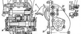
T-4 tractor gearbox . The four-speed, two-speed gearbox, working in conjunction with a two-stage reverse gearbox, provides eight forward gears and four reverse gears. Its body 30 (Fig. below) is attached to the rear axle housing.
T-4 tractor gearbox:
1 — drive shaft of the reverse gearbox; 2 - tray; 3 - glass; 4—drive shaft gear; 5—reducer carriage; 6—reducer fork; 7, 26 and 27—rollers; 8, 25 and 42—covers; 9 — reverse fork; 10 and 20 - clamps; 11 - spring; 12 and 22 - backstage; 13 - column; 14 — reverse gear lever; 15 — blocking roller; 16 — gearbox input shaft; 17-18 — carriage for 1st-5th and 2nd-6th gears; 19 — retainer plug; 21 — gear lever; 23 and 24 — gearbox forks; 28 - 29 - carriage for IV-VIII and III-VII gears; 30 — box body; 31, 32 and 49 - roller bearings; 33 — secondary shaft of the box; 34 - gear III - VII gears; 35 — spacer sleeve; 36 — gear IV-VIII gears; 37— gear II—VI gears; 38 — gear I—V gears; 39 — drain plugs; 40 - glass; 41 — washer; 43 — adjusting bolt; 44 — emphasis; 45 — shims; 46, 47 and 50 - ball bearings; 48 — reverse gear housing; 51—52 — gear block; 53 and 56 — needle bearings; 54 and 55 - axles; 57 — reverse carriage; 58 — splined bushing; 59 — breather plug; 60 — locking roller clamp; 61 — lock stopper
The housing 48 of the reverse gear is screwed to it at the front. The drive shaft 1 of the reverse gearbox and the input shaft 16 of the box are hollow, and the internal drive shaft of the power take-off shaft is passed through them.
The primary shaft rotates in ball 47 and roller 31 bearings. Two carriages 17-18 and 28-29 can move along the shaft splines.
The secondary shaft 33 is manufactured together with a bevel gear. Gears 34, 36, 37 and 38 are installed on it, alternating with spacer bushings 35. The rear end of the shaft rests on roller 32, and the front end on angular contact ball bearings 46.
The shims 45 under the stop flange 44 serve to achieve full engagement of the bevel gears. When removing the gaskets and tightening the bolts, the stop through the cover 42 moves the cup 40 back along with the bearing and shaft.
The gearbox gears are reversible. After one side of the teeth is worn, all gears are turned 180° and carriages 28-29 and 17-18 on the input shaft are swapped, as well as gears 38 and 34 on the secondary shaft.
The reverse gearbox allows you to change the direction and speed of the tractor by changing the number of revolutions and the direction of rotation of the input shaft of the gearbox. The drive shaft 1 of the reverse gearbox is installed coaxially with the input shaft in the cup 3 on roller 49 and ball 50 bearings.
Together with the drive shaft of the gearbox, a drive gear is made, as well as a splined belt, identical in size to the splines of the input shaft of the box. Therefore, when the gearbox carriage 5, mounted on the splined end of the input shaft, is moved forward, it connects the drive shaft of the gearbox and the input shaft of the box with its internal splines.
In the left (along the direction of the tractor) lower corner of the reverse gear housing there is a block of intermediate gears 51-52, rotating on two needle bearings 53 on an axis 54. The large crown of this block is constantly engaged with gear 4 of the drive shaft of the gearbox. Above the gear block there is a reverse carriage 57, which can move along the splines of the sleeve 58, supported through two needle bearings 56 on the axis 55.
Thanks to the long length of the teeth, this carriage remains in constant engagement with carriage 5.
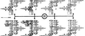
Position of the gears of the reverse gearbox of the T-4 tractor when turned on:
a - accelerated gears; b - slow gears; c — reverse gears. The position designations are the same as in Fig. higher
When the gearbox carriage 5 is in the neutral position, only the drive shaft and gear block rotate. If carriage 5 is moved forward (the position shown in Fig. a), then together with the drive shaft of the gearbox, the input shaft of the box will rotate as a whole.
If you now move the carriage along the splines of the input shaft and engage gears 17 and 38, 18 and 37, 29 and 34, 28 and 36, then accelerated gears V, VI, VII and VIII will be obtained, respectively.
If the gearbox carriage 5 is moved back and engaged with the small gear 51 (Fig. b) of the block, then the input shaft of the box will rotate in the same direction, but slower than the drive shaft of the gearbox. By engaging the same gears of the primary and secondary balls of the box, I, II, III and IV gears are respectively obtained.
When the gearbox carriage is in a neutral position, and the reverse carriage 57 is shifted forward (Fig. c), the latter, while remaining engaged with the gearbox carriage, simultaneously engages with the large gear 52 of the block. In this case, rotation from gear 4 of the drive shaft is transmitted to the large gear 52 of the block, then to the reverse carriage 57 and the gearbox 5. As a result, the input shaft will rotate in the opposite direction and slower than the drive shaft. Therefore, when gears 17 and 38, 18 and 37, 28 and 36, 29 and 34 engage, they receive reverse gears: I, II, IV and III, respectively.
The gearbox and reverse gear have separate shift levers 21 and 14, pivotally mounted in the columns, similar to the shift levers of the T-74 tractor gearbox.
The scenes 12 and 22 are fixed between the covers and columns.
The gearbox carriages are moved by forks 23 and 24, mounted on rollers 26 and 27. The latter are held by clamps 20, above which a locking roller 15 is placed. To more reliably prevent the simultaneous engagement of two gears, a cylindrical lock stopper is installed in the horizontal drilling of the jumper between the rollers 26 and 27. Both rollers have recesses against the stopper. When one of the rollers moves in the longitudinal direction, the bevel of the recess presses on the stopper, presses it into the recess of the other roller and securely fixes the latter.
The gearboxes 5 and reverse 57 are switched by means of forks 6 and 9, moved along fixedly fixed rollers 7. Ball retainers 10, inserted together with springs 11 into the sockets of the forks, when changing gears, enter the annular recesses of the rollers and thereby fix the carriages. The position of the upper ends of the shift levers when engaging various gears is shown in Fig. 116.
Automotive oil (AK-15 in summer and AK-Yu in winter) is poured into the communicating cavities of the gearbox and rear axle housings until the control hole in the rear axle housing is reached. During operation, the oil is thrown into tray 2 by the gears, from where it flows through the hollow axis 55 into the cavity of the reverse gear housing and lubricates its parts.
Gearbox of the T-100M tractor.
Gearbox of the T-100M tractor:
a - section of the box; b - switching mechanism; 1 - input shaft; 2 and 4 — gear block; 3 - body; 5 - oil gauge tube; 6 — filler neck; 7 and 8 — gear block of III and IV gears; 9 - 2nd gear gear; 10 — fifth gear carriage; 11 and 12 — gear block of 5th and 1st gears; 13 — servomechanism drive gear; 14 - secondary shaft; 15—16 — carriage of 1st and 2nd gears; 17—18 — carriage of III and IV gears; 19 — intermediate shaft; 20 — reverse carriage; 21 — adjusting shims; 22 — intermediate gear; 23 - axis; 24 — switching mechanism housing; 25 — internal reverse lever; 26 — bracket; 27 - axis; 28 — roller; 29— outer reverse lever; 30 — gear lever; 31 - seal; 32 — washer; 33 - spring; 34 — strips; 35 — blocking roller; 36 — blocking roller body; 37 — retainer; 38 — shift rollers; 39, 40 and 41 — shift forks for 1st and 2nd, 5th, 3rd and 4th gears; 42 — reverse fork
This box allows you to get five forward and four reverse gears. Housing 3 contains primary 1, secondary 14 and intermediate 19 shafts, which are supported in front by ball bearings and in the rear by roller bearings.
An intermediate gear 22 is installed on the axis 23, rotating on two roller bearings. It is constantly engaged with gear 2 of the block mounted on the input shaft. Double-crown carriages 15-16, 17-18 and reverse carriage 20 are mounted on the splines of the intermediate shaft. The gears are fixedly mounted on the secondary shaft.
Diagram of shafts and gears of the T-100M tractor gearbox:
a - forward travel; b - reverse. The position designations are the same as in Fig. higher
The direction of movement of the tractor is changed by switching the carriage 20 in reverse. When it is moved forward and meshed with the intermediate gear 22 (Fig. a), the intermediate shaft rotates in the same direction as the primary shaft. If you alternately engage gears 15 and 12, 16 and 9, 17 and 8, 18 and 7, you get I, II, III and IV forward gears, respectively.
When the reverse carriage 20 is moved back and engaged with the gear 4 of the block mounted on the input shaft (Fig. b), the intermediate shaft rotates in the opposite direction. Therefore, if we now engage the same gears of the intermediate and input shafts, four reverse gears will be obtained.
To engage V gear, carriage 10 is engaged with gear 11. Since in this case the secondary shaft receives rotation directly from the primary, bypassing the reverse mechanism, the tractor can only move forward in V gear.
The switching mechanism is mounted in housing 24, which is attached to the right side of the box body. Forks 39, 40 and 41, connected respectively to carriages 15-16, 10 and 17-18, are mounted on rollers 38. The lower end of the gear shift lever 30 moves in the slots of the forks, located at the same level.
The reverse fork 42, mounted on the lower roller and connected to the carriage 20, is moved by an internal lever 25, which is mounted on a common roller with an external reverse lever 29. On the side there are horizontal clamps 37 and a vertical locking roller 35.
The gearbox parts are lubricated with oil poured into the housing cavity through neck 6. The oil level is controlled with an oil gauge inserted into tube 5. In summer, automotive-tractor transmission oil (nigrol) is used for lubrication, and in winter, automotive-tractor oil AK-15 is used. At temperatures below - 20° C, it is recommended to use AKZp-6 oil.
Angular gearbox made of satellites
Moderator: User buggy
Angular gearbox made of satellites
Weather report » Sat Mar 28, 2015 6:19 am
Re: Angle gear made from satellites
Post by ed24ru » Sat Mar 28, 2015 7:01 am
Re: Angle gear made from satellites
Weather report » Sat Mar 28, 2015 7:29 am
Re: Angle gear made from satellites
Weather report » Sat Mar 28, 2015 7:31 am
Re: Angle gear made from satellites
Post by RusWin » Sat Mar 28, 2015 9:53 am
Re: Angle gear made from satellites
Weather report » Sat Mar 28, 2015 7:04 pm
Re: Angle gear made from satellites
Post by mmcl200 » Mon Mar 30, 2015 3:30 pm
Re: Angle gear made from satellites
Post by Ivan66 » Mon Mar 30, 2015 8:38 pm
Re: Angle gear made from satellites
Post by Black_Arrow » Fri Apr 03, 2015 11:13 am