Adjusting KAMAZ gearboxes video | KAMAZ
KAMAZ — Rear axle gearbox repair — Part 1 — Disassembly
KAMAZ - Repair of rear axle gearbox - Part 3 - Adjustment of shank bearings
KAMAZ — Rear axle gearbox repair — Part 4 — Adjusting the thermal clearance of bearings
Kamaz gearbox assembly!!!
KAMAZ — Rear axle gearbox repair — Part 5 — Differential assembly
The topic of gearboxes - subtleties
Kamaz - middle axle gearbox - center differential repair
Gearboxes KamAZ average rear 46, 47, 48, 49, 50 teeth 5320 65115 4310 and used from Reduktor-Kama
KAMAZ - Rear axle gearbox repair - Part 2 - Troubleshooting
KAMAZ gearbox plant in Naberezhnye Chelny
Also see:
- Detailed design of a KAMAZ vehicle
- Rear gearbox KAMAZ 53215
- Heating of KAMAZ fuel tanks
- Video of KAMAZ block repair
- Dashboard KAMAZ 65115 euro 3 diagram
- KAMAZ divider bearings
- KAMAZ speedometer needle floats
- Test drive video KAMAZ trucks
- Operating order of KAMAZ 65115 cylinders
- KAMAZ with a cummins 400 engine
- KAMAZ for farming simulator 2014
- Cover for KAMAZ oil tank
- Spark plug for KAMAZ heater
- Green KAMAZ accident
- Connecting a KAMAZ glow plug
Home » News » Adjusting KAMAZ gearboxes video
kamaz136.ru
Adjusting the car's main gears
In the main gear of the car
The axial clearances in the bearings of the drive gear shaft, the bearings of the intermediate shaft of the double final drive, the bearings of the differential box, as well as the meshing of the gears (the position of the drive and driven gears) can be adjusted.
Need for adjustment
occurs when replacing any parts or when bearings are worn out.
The axial clearance of the bearings of the drive gear shaft of the main gear of the GAZ-66 car (see Fig. 71) is checked using an indicator or by shaking the flange 12 by hand.
Adjustment is necessary if the gap exceeds 0.03 mm. For adjustment, spacers 15 are used, installed between the spacer ring and the end of the inner ring of the rear tapered bearing.
The adjustment procedure is as follows:
- disconnect the rear cardan and remove the axle shafts 9;
- unscrew the bolts securing the main gear housing and remove it;
- Unscrew the stop 10, remove the oil scraper tube;
- make marks on the covers 7 and nuts 17, unscrew the bolts and remove the locking plates 8, unscrew the nuts 17, remove the covers 7, remove the differential;
- unscrew the bolts securing coupling 11, remove it and clamp it in a vice;
- Unscrew the nut 13 securing the flange on the drive shaft 14, remove the flange 12, the oil seal cover and the inner ring with the rollers of the outer bearing;
- remove or add one or two shims 15;
- assemble coupling 11 (without oil seal and cover) and tighten nut 13 until it stops, turning flange 12;
- check the tightness of the bearings. When turning flange 12 with a dynamometer, the force should be 1.25-2.9 kg;
- assemble coupling 11 with oil seal, tighten nut 13 and secure with cotter pin; put the coupling in place;
- assemble the main gear.
Screw the differential bearing nuts to the position marked with marks (see paragraph 4). Screw stop 10 of driven gear 6 until it stops, then unscrew it 1/6 of a turn and secure with a nut.
The play of the differential bearings, the lateral clearance and the contact in the meshing of the main gears are adjusted with nuts 17. The bearings are adjusted so that they do not have pre-tightening and axial movement, and then the adjusting nuts are tightened to one notch.
The lateral clearance in the gear mesh is checked with an indicator at four evenly spaced points. For different rear axles, the gap can be 0.15-0.3 mm, but for the gears of one axle it should not change by more than 0.1 mm.
To increase the side clearance, you need to loosen the adjusting nut on the side of the driven gear and tighten the nut on the other side by the same number of notches.
After unscrewing the nuts, they must be tightened, i.e., if you need to unscrew the nut by one notch, it is released by two notches, and then tightened by one notch.
The position of the drive gear relative to the driven gear can be changed by adjusting shims 16 located between the bearing coupling flange 11 and the main gear housing.
To check the engagement of the main gear gears, paint the teeth, brake the drive gear and rotate the driven gear in both directions until a clear contact patch is obtained.
The contact patch should be located in the middle of the tooth and should not extend to the top of the tooth (a slight offset towards the narrow end of the tooth is allowed).
The bearings of the drive gear shaft of the main gears of the ZIL-131 vehicle are adjusted by selecting the thickness of the adjusting washers 10 (see Fig. 69). The bearings should have a slight preload; Axial play is not allowed. The force applied to the holes of flanges 6 and 9 should be 1.3-2.7 kg.
After replacing the bevel gears, it is necessary to adjust the side clearance and gear engagement.
To do this, use adjusting shims 4 and 7. The lateral clearance should be 0.15 - 0.45 mm at the wide part of the tooth, which corresponds to turning flange 6 (for the middle bridge of flange 9) by 0.18 - 0.54 mm when measuring at the radius of the holes for the bolts when the driven gear is stationary.
After adjustment, you need to check the correct engagement of the gears along the contact patch.
How to adjust the rear gearbox of KAMAZ 5320
KAMAZ - Repair of rear axle gearbox - Part 3 - Adjustment of shank bearings
KAMAZ — Rear axle gearbox repair — Part 4 — Adjusting the thermal clearance of bearings
Kamaz gearbox assembly!!!
KAMAZ — Rear axle gearbox repair — Part 1 — Disassembly
KAMAZ — Rear axle gearbox repair — Part 5 — Differential assembly
Kamaz - middle axle gearbox - center differential repair
Repair, adjustment and assembly of Kamaz gearbox
Gearboxes KamAZ average rear 46, 47, 48, 49, 50 teeth 5320 65115 4310 and used from Reduktor-Kama
KAMAZ - Rear axle gearbox repair - Part 2 - Troubleshooting
Adjusting the rear axle gearbox. Part II. Author's technique Zhdankin N.V.
Also see:
- KAMAZ all-terrain vehicle with dissolution
- This is KAMAZ 4310
- Generator relay KAMAZ 4310
- Front axle differential KAMAZ 43118
- Injector puller for KAMAZ
- Crane manipulator based on KAMAZ 7 tons
- Install a KAMAZ 740 engine on the t 150
- KAMAZ all-terrain vehicle restyling
- Belts KAMAZ 65117 cummins
- How to remove the KAMAZ camshaft gear
- Installation of a turbine from KAMAZ on a VAZ 2107
- Compressor KAMAZ single-cylinder head
- KAMAZ 65115 sewer truck technical specifications
- KAMAZ platform side locks
- The procedure for tightening the crankshaft on KAMAZ
Home » New » How to adjust the rear gearbox of KAMAZ 5320
kamaz136.ru
REPAIR OF DRIVE AXLES OF KAMAZ VEHICLES
When repairing, depending on the malfunction, dismantle the drive axle assembly or only the main gear. Disassemble the gearbox into the following assembly units, after draining the oil from the axles and center differential into a clean container (for further use):
— driving bevel gear;
— cross-wheel differential. Remember that the cross-axle differential bearing caps are not interchangeable, since they are machined together with the gear housing;
— driven bevel gear;
— center differential, in case of disassembling the intermediate axle gearbox.
When disassembling, be sure to check the play in the above assembly units, since the assembly must ensure mandatory preload of the tapered bearings. After complete disassembly, wash and check the gearbox parts.
When inspecting parts, check:
— teeth and location of the contact patch on the working surfaces of the teeth; If unacceptable wear or damage (chipping of teeth) is detected, replace the parts with new ones. If the teeth are not properly engaged, find the cause and eliminate it. As spare parts, the drive and driven bevel gears are supplied as a set, selected for noise and contact patch, so if one of them is damaged, replace both gears;
— teeth and contact spots on the working surfaces of the teeth of cylindrical gears; If unacceptable wear or damage (chipping) of the teeth is detected, replace the parts with new ones;
— the condition of the surface of the crosspieces’ spikes, satellites and satellite holes (interaxial and
cross-axle differentials). In case of minor damage, polish the surfaces with fine-grained sandpaper, and in case of serious damage, replace the parts with new ones. In the same way, check the condition of the surfaces of the journals and ends of the axle gears, the drive gears of the rear and intermediate axles, the center differential and their seating surfaces in the differential cups;
— the condition of the surfaces of the satellite support washers, axle gears and drive gears of the rear and intermediate axles; If minor damage is found, repair it and, if necessary, replace parts with new ones;
— inspect all bearings, they should be wear-free, with smooth working surfaces.
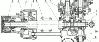
Rice. 186. Main gear of the rear axle: 1-main gear housing; 2 - filler plug; 3 — driven bevel gear; 4 - key; 5 — cylindrical drive gear; 6, 9, 16, 34, 36 — tapered roller bearings; 7, 32 — bearing cups: 8 — bearing cover; 10, 19, 24, 47 — support washers; 11, 49 — nuts; 12, 35 — adjusting washers; 13, 33 — adjusting gaskets; 14, 31, 39 — gaskets; 15 — adjusting nut; 17 — differential cup; 18 — satellite; 20 — crosspiece; 21 — semi-axial gear; 22 — differential cup mounting bolt; 23 — cylindrical driven gear; 25 — satellite bushing; 26, 40 — cylindrical roller bearings; 27 - flange; 28 — reflector; 29 — cuff; 30 - cover; 37 — bevel drive gear; 38 — drive shaft; 41 - cover; 42, 48 — washers; 43 — differential bearing cover; 44 - stopper; 45 — differential bearing cover mounting bolt; 46 — spacer sleeve
To disassemble the final drive of the rear axle, unscrew the self-locking bolts securing the stoppers of the rear axle differential bearing nuts and remove the stoppers 44 (Fig. 186). Bend the locking plates of the bolts securing the differential bearing caps and unscrew the bolts 45. Remove the bearing caps 43, the adjusting nuts 15 of the differential bearings and remove the rear axle differential. Undo the cotter pin and unscrew the nut 49 securing the rear axle flange and remove the flange 27. Unscrew the bolts securing the drive bevel gear bearing cup cover, remove the cover 30 and support washer 47.
Unscrew the cover mounting bolts and remove cover 41. Press out drive shaft 38 as an assembly with the drive bevel gear. Unscrew the cover fastening bolts and remove the cover 8. Unfasten and unscrew the nut 11 and remove the support washer 10. Take out the bearing cup 7 assembled with bearing 9 and the outer race of bearing 6. Remove the adjusting washers 12 and take out the driven bevel gear assembly unit.
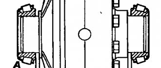
To disassemble the rear axle differential, compress the inner rings of the tapered roller bearings 16 with the differential cup 17. To do this, place the grips 1 of the puller (Fig. 187) behind the inner ring of the bearing and secure with screws 3. Resting tip 2 against the end of the differential cup, screw screw 5 into the yoke 4 until the inner ring of the bearing is completely removed.
Unscrew the self-locking nuts securing the differential cups, remove the bolts 22 (see Fig. 186), disconnect the differential cups 17, take out the driven spur gear 23, side gears 21, remove the support washers 19, 24, remove the satellites 18 from the crosspiece 20.
To disassemble the drive bevel gear, remove cup 6 (Fig. 188) with bearing 15, adjusting washers 1 and spacer sleeve 2. Press out drive shaft 4 of the rear axle, press the inner ring of tapered roller bearing 5 with a puller. To remove, install the edges of wedges 8 (Fig. 189 ) between the inner ring of the bearing and the gear and, screwing screw 6 into cross-beam 7, tighten them. Place the grips 1 by the wedges 8 and fix them in this position with screws 3. Pressing the tip 2 against the end of the gear and screwing the screw 3 into the traverse 4, remove the ring.
To disassemble the driven bevel gear, press the driven bevel gear 3 (see Fig. 186) together with the cylindrical roller bearing 26. Remove the key 4. Use a puller to compress the inner ring of the bevel roller bearing 6 in the same way as removing the inner ring of the drive bevel gear bearing (see Fig. 189).
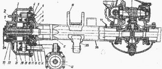
Dismantling the main drive of the intermediate bridge. Remove the center differential mounting bolts and remove the center differential. Remove the self-locking bolts securing the bearing housing of the drive bevel gear. Undo the cotter pin and unscrew the nut 38 (Fig. 190), remove the washer 39 and remove the flange 37. Unscrew the cover bolts and remove the cover 34. Remove the rear shaft 31 as an assembly with bearing 32.
Disassembling the driven bevel gear and intermediate axle differential assemblies is similar to disassembling them at the rear axle main gear.
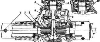
To disassemble the center differential (Fig. 191), unscrew the filler plug 14, unscrew the lock nut and unscrew the set screw 13. Unscrew the bolts securing the locking mechanism and remove the locking mechanism 16. Remove the fork 17 of the locking mechanism together with the locking clutch 20. Unscrew and unscrew the nut 1, remove the support washer 2 and take out the flange 3 of the center differential. Unscrew bolts 5, remove cover 29 and press out the center differential cups as an assembly. Remove the locking ring 18, coupling 19. Unscrew the self-locking bolts 26, disconnect the front and rear cups 8 and 23. Remove the gears 22 and 25 of the drive of the intermediate and rear axles, support washers 7 and 10, satellites 9 of the center differential from the crosspiece 24.
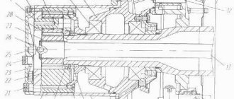
Rice. 192. Drive bevel gear of the main drive of the intermediate bridge: 1 — lock washer; 2 - lock nut; 3 — bearing washer; 4 — bearing nut; 5 - locking pin; 6, 10 — tapered roller bearings; 7 — cup of bearings; 8 — adjusting washers; 9 — spacer sleeve; 11 - bevel drive gear
Dismantling the drive bevel gear (Fig. 192).
Unlock and unscrew nut 2 with a special wrench, which serves as an adapter for a 46 mm open-end wrench (Fig. 193), remove lock washer 1 (see Fig. 192), and bearing washer 3. Unscrew the nut 4 of the bearing assembly with the locking pin 5. Remove the cup 7 assembled with the bearing 6, adjusting washers 8, spacer sleeve 9. Using a puller, press the inner ring of the tapered roller bearing 10 from the drive bevel gear 11. Removal is carried out in the same way as removing the inner ring of the bearing from the drive bevel gear of the rear axle final drive.
To disassemble the main drive of the front axle, it is necessary to unscrew the bolts securing the stoppers of the front axle differential bearing nuts and remove the stoppers. Having bent the locking plates 35 (see Fig. 185) of cover 1, unscrew the adjusting nuts 34 of the bearings and remove the differential from the front axle final drive housing. Unscrew the bolts and remove the cover 27 with the gasket for the bearing housing of the drive cylindrical wheel. Unscrew and unscrew nut 29, remove support washer 28. Screw in M12X technological bolts
1.25X50 (2 pcs.), press out cup 26 assembled with bearing 25 and outer race of bearing 24. Remove the drive spur gear assembly 23 from the crankcase. Use a puller (see Fig. 187) to compress the inner ring of the tapered bearing 24 (see Fig. 185), roller bearing 22, driven bevel wheel 21 and key 9.
Dismantling the assembly units of the drive bevel gear and the differential of the main drive of the front axle is carried out similarly to their disassembly of the main drive of the rear axle.
When installing and adjusting the bearings and gears of the gearbox, install the tapered roller bearings of the drive bevel gear shaft with preload. The torque required to rotate the drive gear shaft in the bearings should be 0.78... 1.57 Nm (0.08... 0.16 kgf.m). Measure the torque while rotating the flange continuously in one direction after at least five full rotations of the shaft. The bearings must be lubricated. When checking the rotation torque of the rear axle drive gear, the bearing housing cover must be moved towards the flange so that the centering protrusion of the cover comes out of the bearing housing seat and the oil seal does not resist the rotation of the gear.
Adjust the bearings of the drive bevel gear by selecting shims from the kit supplied as spare parts.
Install two washers between the inner ring of the front bearing and the spacer sleeve. After the final adjustment of the bearings, tighten the nut for securing the bearings of the drive gear of the rear axle (tightening torque 235... 353 Nm (24... 36 kgf.m) and pin it. At the intermediate axle gearbox, tighten the nut for securing the bearings with a torque of 235 N.m (24 kgf.m) , place the bearing washer and tighten the nut until the hole in the bearing washer aligns with the locking pin of the nut. Then install the lock washer, aligning its protrusion with one of the holes in the bearing washer, and tighten the lock nut with a torque of 235 ... 353 Nm (24 ... 36 kgf.m), bend the edge of the lock washer onto the edge of the locknut.When tightening the nuts, rotate the drive gear so that the bearing rollers take the correct position between the conical surfaces.
After assembling the drive gear, measure dimension E (see Fig. 188, 192), since it will be necessary when adjusting the engagement of the bevel gears.
The drive and driven bevel gears of the gearbox are selected at the factory into sets according to the contact patch and the lateral clearance in the mesh, ground in and branded with the serial number of the set. In addition, at the rear end of the drive bevel gear the value of the
deviation (correction in hundredths of mm) from the theoretical installation size of 81 mm (Fig. 194). The “+” sign corresponds to the distance of the drive gear from the driven axis, the “-” sign to its approach.
When the car is running, the gears are worn in one another. Therefore, if it is necessary to replace gears, replace both gears as a set. Newly installed bevel gears must have the same set serial number.
When installing new bevel gears of the gearbox, adjust them according to the contact patch and the lateral clearance in the mesh (Table 33), which should be 0.20... 0.35 mm.
The contact patch on both sides of the driven bevel gear tooth should have a length equal to approximately 1/2 ... 2/3 of the tooth length on the forward side, 1/2 ... 3/4 of the tooth length on the reverse side. The minimum width of the contact patch in the middle part should be equal to 1/2 of the active tooth height. The contact should be located closer to the inside of the tooth, but should not extend to its edge. The contact patch extending to the edge of the outer (wide) part is also unacceptable. On the drive gear teeth, the contact patch may reach the top edge. The contact patch is obtained by rotating the drive gear in both directions while simultaneously braking the driven gear by hand.
When installing new bevel gears into the gearbox, determine the thickness of the shim pack installed between the drive bevel gear bearing housing flange and the gearbox housing. The thickness of the shim package is determined by the formula:
S = (81 ± correction) + E - B, where E is the actual size from the end of the drive gear to the flange of the cup (see Fig. 188, 192);
B is the actual size of the gearbox from the front end to the axis of the driven bevel gear (see Fig. 186, 190).
Assemble the adjusting gasket package from the number of gaskets indicated in the table. 34.
Be sure to install at least 2 gaskets with a thickness of 0.05 mm under the flange of the glass. and 0.1 mm thick, at least 2 pcs. Select the rest as needed. Thin shims should be placed on both sides of the shim set to obtain a sealed joint.
Tighten the fastening bolts of the intermediate axle drive bevel gear cup to a torque of 98.1... 122.6 N.m (10... 12.5 kgf.m), the rear axle - to a torque of 58.9... 88.3 N.m (6... 9 kgf.m). When finally installed in the crankcase, the drive gear should rotate smoothly, without jamming.
The spur gear shaft rotates in one roller and two tapered bearings, which are mounted with preload.
Adjust the bearings by selecting shims from the kit supplied as spare parts. Install two washers between the inner rings of tapered roller bearings. The torque required to rotate the driven bevel gear after adjustment should be 0.98 ... 3.43 N.m (0.1 ... 0.35 kgf.m). Measure the torque during continuous rotation in one direction after at least five full revolutions of the shaft. The bearings must be lubricated.
Install the driven bevel gear after installing the drive bevel gear. Fully tighten the bolts securing the covers and cup, bearings of the drive bevel gear.
Before installing the driven bevel gear assembly, remove the outer bearing cup. Then install the driven bevel gear assembled with the drive cylindrical gear into the gearbox housing and press it with a glass to a position that ensures backlash-free engagement of the bevel gear pair. When pressed, measure dimension F (see Fig. 186, 190) between the crankcase and the cup flange. After this, determine the thickness of the required shim package using the formula:
S = F + D,
where D = 0.317... 0.555 mm is the thickness of the shim package, equal to the axial displacement of the driven bevel gear to compensate for the lateral clearance in the gear mesh. After installing the driven bevel gear, tighten the bearing nuts of the drive cylindrical gear with a torque of 343 ... 392 N.m (35 ... 40 kgf.m), and the bolts securing the cover and cup with a torque of 58.9 ... 88.3 N.m (6 ... 9 kgf.m). After this, check the lateral clearance in the teeth of the conical pair, which should be 0.2 ... 0.35 mm. Measure the gap with an indicator mounted on the wide part of the tooth, and for at least three teeth of the driven gear, located at approximately equal angles around the circumference.
To install the cross-axle differential, assemble it by aligning the cups with the marks in the kit. Dip the side gears and satellites into engine oil before installing them in the differential cups. When assembled: the differential gears should turn easily by hand, without jamming. The tightening torque of the self-locking nuts of the differential cup mounting bolts should be 137...157 N.m (14...16 kgf.m).
Install the assembled differential into the gearbox housing after installing the drive and driven bevel gears and adjusting their engagement. After installing the assembled differential in the gear housing housings, tighten the adjusting nuts by hand until they fit snugly against the bearings, then install the differential bearing caps.
To avoid damaging the threads on the crankcase, covers and nuts, when installing covers, ensure that the threads on the mating parts match.
Tighten the bolts together with the locking plates securing the differential bearing covers to a torque of 98.1... 117.7 N.m (10... 12 kgf.m). Using the adjusting nuts, install the crown of the driven spur gear symmetrically relative to the crown of the drive gear. The contact patch on both sides of the tooth (rotation in both directions) should correspond to the patch shown in Fig. 195. Adjust the preload of the differential bearings by sequentially and evenly tightening both adjusting nuts until the distance A (see Fig. 186) between the differential bearing caps increases by 0.1... 0.20 mm (measure the distance between the pads for the nut stoppers) . In this position, lock the adjusting nuts. Tighten the differential bearing cap mounting bolts to a torque of 245... 314 N.m (25... 32 kgf.m) and lock by bending the washers onto one of the faces of the bolt heads and onto the cover.
When adjusting the bearings, rotate the differential several times until the rollers are in the correct position between the conical surfaces of the rings. After assembling the gearbox, the lateral clearance in the teeth of the spur gear pair should be 0.1... 0.5 mm. Tighten the nuts of the studs securing the gearbox to the axle housing with a torque of 157… 177 N.m (16… 18 kgf.m). The order of tightening the nuts is “crosswise”.
To install the center differential, assemble it by matching the numbers on the cups. In the assembled differential, the gears should turn easily by hand, without jamming. The tightening torque of the self-locking bolts securing the center differential cups should be 53.9... 68.7 N.m (5.5... 7 kgf.m). Before installing the cover assembly with the oil seal on the center differential shaft, place grease between the working edges of the oil seal. Tighten the cover fastening bolts with a torque of 35.3...49.1 N.m (3.6...5 kgf.m), tighten the center differential shaft flange nut with a torque of 245...294 N.m (25...30 kgf.m) and seal it. When assembled, the center differential should turn without jamming.
Install the assembled center differential locking mechanism into the center differential housing. Screw the yoke set screw and yoke locknut through the center differential housing filler hole.
When air is supplied under pressure of 196 kPa (2 kgf/cm2) into the chamber of the center differential locking mechanism, the locking clutch fork should move to its extreme position until it stops at the center differential housing. When air is released from the chamber, the clutch fork must return all the way to the locking mechanism body.
After assembly and checking, install the housing with the center differential on the gearbox housing and secure with bolts, ensuring a tightening torque of 36.3...49.1 N.m (3.6...5 kgf.m). Press the ball bearing onto the rear shaft of the intermediate axle gearbox and insert it into the gearbox housing, then secure the bearing cover assembly with the oil seal with bolts, ensuring a tightening torque of 35.3... 49.1 N.m (3.6... 5 kgf.m). Before installing the cover, place grease between the working edges of the oil seal. Install the flange and washer on the rear shaft and tighten the flange nut to a torque of 245... 294 N.m (25... 30 kgf.m), then secure it with a cotter pin.
Adjust the cross-axle differential locking mechanism (see Fig. 196) in the following order:
— remove the main gear;
— remove the cover of the locking mechanism;
— remove the piston with the rod;
— install the locking clutch in a position in which the distance from plane A of the clutch ring gear to the axis of the hole d= 338+0215 mm in the axle housing is 168 mm;
— measure dimension B from the surface of the fork pin to the reference plane of the crankcase flange;
— assemble the piston with the rod in size B+7 mm, lock it with a nut and install it in the axle housing, tighten the bolts securing the cover and diaphragm evenly, and the tightening force should ensure tightness, without excessive compression of the sides of the diaphragm;
— check the travel of the locking clutch when supplying air to the diaphragm, which should be 14 mm.
content .. 51 52 53 ..
Adjusting the rear axle gearbox of KAMAZ
KAMAZ — Rear axle gearbox repair — Part 1 — Disassembly
KAMAZ - Repair of rear axle gearbox - Part 3 - Adjustment of shank bearings
KAMAZ — Rear axle gearbox repair — Part 4 — Adjusting the thermal clearance of bearings
KAMAZ — Rear axle gearbox repair — Part 5 — Differential assembly
Kamaz - middle axle gearbox - center differential repair
Kamaz gearbox assembly!!!
KAMAZ - Rear axle gearbox repair - Part 2 - Troubleshooting
Adjusting the rear axle gearbox. Tutorial. Part 1
Adjusting the rear axle gearbox. Part II. Author's technique Zhdankin N.V.
The topic of gearboxes - subtleties
Also see:
- KAMAZ tire weight
- Maintenance and current repairs of KAMAZ vehicles
- KAMAZ wheel tire
- Fuel supply system KAMAZ 740
- KAMAZ cars children's video
- KAMAZ 740620 wiring diagram
- Modernization of KAMAZ gearbox
- KAMAZ 5410 with a manipulator
- Watch a video about KAMAZ dump truck
- KAMAZ 4x4 rear suspension
- Welding units on KAMAZ chassis
- Removing the KAMAZ 6520 gearbox video
- Cabin lift pump KAMAZ 6520
- KAMAZ engine repair calculation
- Heated fuel filters for KAMAZ
Home » Popular » Adjusting the rear axle gearbox of KAMAZ kamaz136.ru
Adjusting the rear axle gearbox KAMAZ video
KAMAZ — Rear axle gearbox repair — Part 4 — Adjusting the thermal clearance of bearings
KAMAZ - Repair of rear axle gearbox - Part 3 - Adjustment of shank bearings
KAMAZ — Rear axle gearbox repair — Part 5 — Differential assembly
KAMAZ — Rear axle gearbox repair — Part 1 — Disassembly
Kamaz gearbox assembly!!!
KAMAZ - Rear axle gearbox repair - Part 2 - Troubleshooting
Adjusting the rear axle gearbox. Tutorial. Part 1
Repair, adjustment and assembly of Kamaz gearbox
Adjusting the rear axle gearbox. Part II. Author's technique Zhdankin N.V.
Assembly of the Kamaz rear gearbox!
Also see:
- Fuel injection pump KAMAZ 53215
- Tailgate KAMAZ 53215
- A log truck with a hydraulic manipulator based on KAMAZ 43118
- KAMAZ master 2015 accident KAMAZ karginov video
- A warrant officer teaches a cadet on a KAMAZ
- Naberezhnye Chelny KAMAZ plants
- Boring KAMAZ engine
- What does a KAMAZ hub look like?
- Armored car KAMAZ 5350
- Seven under KAMAZ
- KAMAZ 55111 with gas-diesel
- How to remove the box on KAMAZ 53212 video
- Pile driving rig based on KAMAZ
- Gearbox lever KAMAZ 4308
- Susan manipulator on KAMAZ
Home » Video » Adjusting the rear axle gearbox KAMAZ video
kamaz136.ru
Adjusting the rear axle shank of KAMAZ 5320
KAMAZ - Repair of rear axle gearbox - Part 3 - Adjustment of shank bearings
KAMAZ — Rear axle gearbox repair — Part 4 — Adjusting the thermal clearance of bearings
Repair, adjustment and assembly of Kamaz gearbox
KAMAZ — Rear axle gearbox repair — Part 1 — Disassembly
Kamaz gearbox assembly!!!
KAMAZ — Rear axle gearbox repair — Part 5 — Differential assembly
KAMAZ - Rear axle gearbox repair - Part 2 - Troubleshooting
Kamaz - middle axle gearbox - center differential repair
Adjusting the rear axle gearbox. Part II. Author's technique Zhdankin N.V.
KamAZ 5320 resuscitation
Also see:
- What to do in the new KAMAZ
- Make a booth for KAMAZ yourself
- Truck crane based on KAMAZ 32t
- Ets 2 engines for KAMAZ
- Firm MIG KAMAZ
- What does KAMAZ 5410 look like?
- Dashboard KAMAZ 53504
- How to change the universal joint on a KAMAZ
- KAMAZ concrete pump in operation
- KAMAZ dump truck until 1998
- Cross-country ability of KAMAZ with a trailer
- How to install a Cummins engine on a KAMAZ
- KAMAZ flatbed trailer length
- Technological lubricant KAMAZ 740
- Spare parts KAMAZ EKB
Home » Selections » Adjusting the rear axle shank of KAMAZ 5320
kamaz136.ru
Repair of KAMAZ drive axles
Content:
Features of KAMAZ drive axles
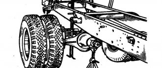
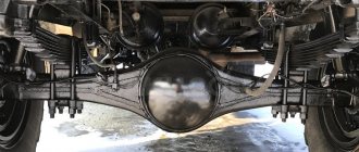
On KamAZ vehicles with a 6 X 4 wheel arrangement, two drive axles are installed - middle and rear, and on vehicles with a 6 X 6 wheel arrangement, all drive axles are installed.
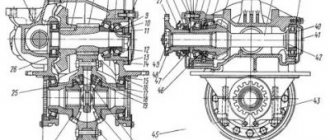
Rice. 1. 1 — main gear housing; 2 — stud securing the main gear of the car; 3 — rear axle housing; 4 — right axle shaft; 5 - plug; 6″ — magnetic plug; 7 — driven cylindrical gear of the main gear; 8 — left axle shaft; 9 — spring support; 10 t - reaction rod bracket; 11 — brake chamber; 12 — hub with brake mechanism assembly; 13 — hub seal; 14.15 - tapered roller bearings; 16 — wheel hub; 17 — nut for fastening bearings with a lock washer; 18 — lock nut; 19 — axle shaft flange; 20 — clamp; 21 — spacer ring; 22 — brake drum; 23 — breather; 24 — drive bevel gear shaft; 25 — bearing; 26 — hole for filling oil; 27 — driven bevel gear; 28 - drive cylindrical gear.
The design of all drive axles is the same. Each axle consists of an axle housing, final drive, differential and axle shafts. The middle axle differs from the rear axle in that the main gear has a lockable center differential and there are separate parts designed to interface the differential with the axle. The drive axle of a KamAZ vehicle is shown in Fig. 93. Torque is transmitted to the main gears of the drive axles through the center differential. The main transmission of the bridges is two-stage. The first stage consists of a pair of bevel gears with spiral teeth, the second stage - of a pair of cylindrical gears with oblique teeth. Depending on the purpose of the vehicle, the main gears are installed with the following gear ratios: on vehicles operating with trailers and truck tractors - 7.22 and 6.53; on single cars - 5.94 and 5.43. The drive bevel gears of the middle and rear axles differ in their shanks. The driven bevel gears are the same. The differential assembly with tapered bearings is located in the housing of the main gear housing. After installing the differential, caps are installed on the outer bearing races. The center differential consists of front and rear cups, inside of which bevel gears drive the rear and middle axles, respectively. To increase cross-country ability in off-road conditions and improve the traction qualities of the vehicle when driving on slippery and snowy roads, the design of the center differential has a locking mechanism, which consists of gear couplings, a rod with a fork, a diaphragm chamber and a control valve. The drive axle housings are welded from stamped steel beams. Crankcase covers, flanges for fastening main gears and brake calipers, wheel hub axles, brackets for fastening reaction rods and spring supports are welded to the bridge beams.
Possible bridge malfunctions and ways to eliminate them
During operation, the drive axles, like other units of the KamAZ vehicle, demonstrated failure-free operation over a period of 300 thousand kilometers. The main parts of the drive axles withstand the entire depreciation life of the vehicle. Bevel gears are designed by the manufacturer for the entire period of operation. When operating vehicles and when undergoing major repairs, drive axles may have the malfunctions listed in Table. 1. Before eliminating defects in parts during major repairs, drive axles are subjected to external washing, disassembly and washing of parts. After draining the oil, the drive axles are disassembled into the following units: main gear, drive bevel gear, cross-axle differential, driven bevel gear and center differential (middle axle). When removing the drive and driven bevel gear units, the inter-axle differential, and the center differential of the middle axle from the main transmission, the presence of preload on the tapered bearings, which is ensured during assembly, is checked. The cross-axle differential bearing caps are not interchangeable, since they are processed together with the crankcase, so they cannot be disassembled.
External signs of malfunctions | Causes of interface malfunctions and part defects | Remedy |
| Knocks in drive axles when moving sharply | Wear of bevel gears, increased clearance in the mesh of bevel gears | Remove the required number of gaskets from under the flange of the bearing cup to compensate for wear, then check the correctness of the contact patch in the mesh of the bevel gears |
| Increased noise when driving a car at a speed of 30–60 km/h | The contact patch is shifted towards the wide part of the driven gear teeth | Adjust the gear engagement along the contact patch, as shown in Fig. 2, 2 |
| Increased noise when braking a car and trailer | The contact patch is shifted towards the narrow part of the teeth of the driven bevel gear | The same, Fig. 2, 3 |
| Continuous “howling” when the car is moving | Limit wear or damage to gears Limit wear of bearings | Replace gears Replace bearings, adjust gear mesh |
| Pulsating noise when engaging the clutch and shifting gears | The contact patch is located on the tops of the teeth | Adjust the gear engagement according to the contact patch. |
| Lubricant leakage through seals and cover connectors | Seals are worn out | Replace the seals and tighten the cover bolts |
a - adjustment of the contact patch on the gear teeth of the drive axles: PH - during forward travel; Z X - in reverse; NPS—direction of gear movement; -> mandatory; -> if necessary; 1 - with normal gear engagement; 2 - the driven gear must be moved towards the driving gear; 3 - move the driven gear away from the driving gear; 4 - the drive gear must be moved towards the driven gear; 5 - move the driven gear away from the driven gear; b - correct location of the contact patch on the driven spur gear: Ln - length; L p - width; /с - size difference between the width of the tooth and the length of the contact patch
Adjusting the KamAZ rear axle gearbox
Are you interested in adjusting the KamAZ rear axle gearbox?
Quick links (click): Price for KamAZ rear axle gearbox adjustment DELIVERY IN RUSSIA 6 MONTHS WARRANTY
WATCH A VIDEO!!!
Reducers translated from Latin (Mindere) means reducing. Engineers say that it is impractical to transfer traction torques from engines to the truck's drive wheels at the same speed as the crankshaft. Known data, on average, crankshafts make 2630 rotations per minute. KamAZ gearboxes consist of the following parts: drive shaft, bevel and cylinder gears, crosspiece, cast iron housing, differential cup, cardan flanges, ball bearing, tapered roller bearing, satellite gear with a copper support washer. Since the main gear serves to transmit and change torques from the cardan shafts to the traction wheel, and vehicles can have all traction axles, the main gears are divided into front-wheel drive, middle-wheel drive, and rear-wheel drive. Front, middle, rear drive gearboxes - all can have different properties in terms of gear ratio, efficiency, converted power, maximum centripetal speed, etc. Thus, the dominant service of gearboxes is to reduce the crankshaft speed to the required speed of the drive axle by installing large-diameter gears. As a result of a decrease in frequency, an increase in the traction force of the axle axles is detected. The cars have the best parameters in terms of power and cross-country ability when driving over rough terrain...
We deliver Adjustment of the KamAZ rear axle gearbox throughout the Russian Federation and Kazakhstan: Nizhny Tagil, Cheboksary. Zlatoust Kostroma Zhirnovsk Voskresensk Troitsk Velikiye Luki Sovetsk Grozny Solnechnogorsk Yoshkar-Ola Kaliningrad Temryuk Orekhovo-Zuevo Tuapse Kazan Nizhny Novgorod Kirensk Zhukovsky Kirov Kherson. Saratov Lipetsk Cherepovets Lisichansk Lukhovitsy Chekhov Olenegorsk Rostov-on-Don Kropivnitsky Naberezhnye Chelny Armavir Simferopol Naryan-Mar Sergiev Posad Nikolaev Voronezh Vinnitsa Prokopyevsk Nizhnyaya Tura Tyumen Uralsk Chernigov Magnitogorsk Iskitim Mineralnye Vody Tuymazy Novy Urengoy Vladimir Kursk Neftekamsk Minsk Barnaul Volgograd. Rudny Verkhnaya Salda Syzran. Yaroslavl Arkhangelsk. Almaty Verkhnyaya Pyshma Nadym Usinsk Ust-Ilimsk Pskov Omsk Irkutsk Dmitrov Zaporozhye Stavropol Severodonetsk Volkhov. Magadan Salavat Kokshetau Ulan-Ude Arzamas Vladivostok Nevinnomyssk Sovetsky Tambov Murmansk Yelets Aktobe. Atyrau. Labinsk Kostanay Tula Saransk Volzhsky Brovary Reutov Malin Blagoveshchensk St. Petersburg Makhachkala Ivanovo. Dedovsk Moscow Ekaterinburg Nizhnevartovsk Komsomolsk-on-Amur Inta Samara Shebekino Nalchik. Ust-Kut Yakutsk Klin Kotlas Krasnoturinsk Ufa. Dnepr Lobnya Slavyansk Berdsk Vladikavkaz Gomel Balashikha Krasnodar Petrozavodsk Belgorod Kimry Krasnoyarsk Syktyvkar Cherkassy Kandalaksha Voznesensk Surgut Sestroretsk Kramatorsk Poltava Mines Novokuznetsk Langepas Orel Dzerzhinsk Lesosibirsk Vidnoe Kurgan Penza Achinsk. Khabarovsk. Yeniseisk Buzuluk. Murom Yuzhno-Sakhalinsk Dimitrovgrad Kropotkin Kumertau Tver Ussuriysk Tomsk Chernivtsi Sumy Vologda Taganrog Georgievsk Vsevolozhsk Mytishchi Oktyabrsky Sochi Abakan Angarsk Izhevsk Lyubertsy Novosibirsk Orsk Satka. Mirny Podolsk Gatchina Bryansk Melitopol Perm Kogalym. Novorossiysk Norilsk Biysk Rossosh Chisinau Taishet Belorechensk. Tolyatti Semikarakorsk Kharkov Salekhard Petropavlovsk Noyabrsk Astrakhan Domodedovo Berdyansk Nyagan Stary Oskol Kemerovo Lakes Veliky Novgorod Chita. Serpukhov Aldan Zelenograd Volgodonsk Astana Liski. Glazov Grodno Kyzyl Gelendzhik Miass Ryazan Chelyabinsk Smolensk Ulyanovsk Mikhailovka Khimki Bratsk. Krivoy Rog Karaganda Aleksandrov Sterlitamak Kaluga Segezha Khanty-Mansiysk Lomonosov Ukhta Nefteyugansk Uman Elista Orenburg, etc.
reduktor-kama.ru
- How to turn on the railway on a Kamaz
- KAMAZ Euro starter relay
- Heater for Kamaz
- Air tubes KAMAZ
- How to start driving a Kamaz
- How to change the kingpin on a Kamaz
- Kamaz autonomous vehicle device
- Kamaz 65117 gearbox diagram
Kamaz divider diagram
KAMAZ brands- 355102 KAMAZ