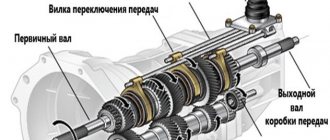
Every owner, owner of a plot, always wants to process it in the best possible way, but for this he needs to have a good mechanism for processing; small tractor or walk-behind tractor. It can be purchased if sufficient funds are available. What if they don't exist yet? There is an exit!
You can design a mechanical unit yourself—a minitractor—to work in your garden, plot, or field. What is needed for this?
- ability to make a walk-behind tractor;
- machine parts;
- tools for work.
If you need help, then on the Internet you can find a lot of suggestions and tips on how to make a walk-behind tractor with your own hands.
What is a reverse gearbox
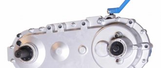
When planning to make a reversible gearbox with your own hands, you must first become familiar with this important detail in more detail. It is a special mechanism that, by transmitting the converted energy received from the engine, activates the main mechanisms of the unit. Similar devices are widely used in Buran snowmobiles and walk-behind tractors from various manufacturers. There are several types of gearboxes, among which the following types can be mentioned:
Each type has its own characteristics, advantages and disadvantages, which are worth studying in more detail. Reducing products are intended for use in cases where it is necessary to significantly reduce the number of revolutions, increasing the torque. As a rule, such a need arises in the field of agriculture, since reduction gearboxes are universally installed on tractors.
The angular gearbox seems to be one of the most effective, designed to ensure correct interaction of the power unit with the transmission. Due to their simple design, as well as long service life, such products are widely used in walk-behind tractors of various models.
The simplest design is the gear reducer, which is distinguished by a high degree of reliability and high wear resistance. The cost of such products is extremely low; they are used to transfer engine energy to the wheels.
Reversible modifications, for example PP 300, differ significantly from all other types of devices, since they can significantly expand the capabilities of the unit. They are equipped with a clutch placed between bevel gears, allowing the equipment to move in the opposite direction. It should be mentioned that this type of mechanism does not allow for impressive movement speeds.
Reverse mechanism device
Having found out the features that the 3D6 marine diesel engine and other types of reverse gearboxes have, it is necessary to become more familiar with its design. It is much more complex than other analogues, due to the need to convert movement in the opposite direction.
The main elements of its design include:
- coupling body, cover;
- discs - rear, front, pressure;
- forward/reverse shafts, as well as output;
- gear mechanisms, including driving and intermediate elements.
A homemade unit in its technical characteristics is almost completely identical to purchased analogues from various manufacturers, for example, Tehnomaster. However, the cost of its production will be significantly lower.
Types of gear units
The transmission of rotational motion from the motor shaft to the actuator shaft can be carried out by direct connection of the axes, if the speed and power of rotation of the engine are acceptable for operation, and the axes of the drive and driven shafts coincide. Such cases are extremely rare, and with several attachments for different purposes, direct transmission absolutely cannot be used. To match the speed and power of the drive and driven shafts, 4 types of mechanisms and their combinations are used. Main types of gears:
The worm gear is structurally limited by the speed-reducing function; the rest can be used in both downshifts and overdrives. In addition, such a gearbox always has a driven axis perpendicular to the drive shaft. This scheme is called an angular gearbox. In addition to the worm gear, you can change the direction of the axis using a spatial planetary mechanism. Belt and chain drives keep the driven axis parallel to the engine axis. In simple devices, reverse is possible only when the rotation of the engine changes.
Motoblocks use engines with a high number of revolutions per minute, which can be verified in the product data sheet. This means that you need to make a gearbox with your own hands to reduce the speed, and it is better to choose what type of homemade gearbox for a walk-behind tractor, knowing the characteristics of each type.
Belting
The pulley or belt that transmits rotation from shaft to shaft is familiar to every motorist who has looked under the hood of the engine compartment. The rotation speed reduction coefficient is determined by dividing the radius of the small driven wheel by the radius of the large driving wheel.
The advantages of belt gearboxes are their ease of manufacture and repair, and a wide variety of parts. And the disadvantages of the belt:
- belt stretching, decreased adhesion to the pulley due to temperature and wear;
- slippage during sudden increases in torque;
- short service life.
Read also: Dimmer for adjusting engine speed
The shortcomings are compensated by using a spring-loaded roller that presses on the surface of the belt between the wheels, and by using a toothed belt on pulleys with transverse chamfers. Belt gearboxes require the drive and driven pulleys to be in the same plane; bending or twisting the belt will quickly lead to it breaking.
Chain type
The operating principle of a chain drive is similar to a belt drive, but sprockets are installed instead of pulleys, and the belt is replaced by a chain. Such a homemade gearbox will not allow slipping, and under similar conditions it will work much longer.
Just like a belt gearbox, a chain gearbox must have drive and driven sprockets in the same plane, and its gear ratio is calculated by the ratio of their teeth. The weight of this design is greater than that of a belt design, but it is safer to install it on powerful walk-behind tractors.
Unlike a belt drive, a chain drive requires caution or additional protective measures. If a rotating implement collides with a thick root in the soil, its drag force will be transferred to the motor, possibly damaging it. Until the engine fails or switches off, it will try to rotate with maximum power along with the frame around the driven axis of the gearbox. The greater the engine power, the stronger the tipping torque will be.
The gear ratio of a chain gearbox can be higher than that of a belt gearbox of the same size, since the drive sprocket, even having a small size, will not allow the chain to slip.
In terms of cost, ease of assembly, and prevalence of parts, a chain drive is not inferior to a belt drive.
Using gears
A walk-behind tractor with a gear reducer is more reliable and durable than one with a chain or belt drive. Gear structures are installed on factory products, and not only on walk-behind tractors. The units are small in size as a result of combining two gears with different diameters on one axis. For a walk-behind tractor, for example, a gearbox from an Ant scooter is perfect. But you can make your own using gears from motor vehicle gearboxes.
The required gear ratio can be provided by a planetary mechanism, in which satellite gears are installed between the outer and sun gears, mounted on a fixed ring - the carrier:
For a reduction gearbox, the sun gear is mounted on the drive shaft. The planetary gear carrier is mounted on a stationary housing, and the outer gear is connected to the actuator, rotating in the direction opposite to the sun gear.
The gear ratio of such a gearbox can be calculated as the ratio of the number of teeth on the sun gear to the number of teeth on the external gear.
To change the direction of the axis of rotation in gearboxes, a spatial planetary mechanism is used, in which the gears, in order to change the direction by 90 degrees, must be beveled to a cone of 45 degrees each. The diameter of the gears can be different, which can be used to change the gear ratio.
For a walk-behind tractor, such an angular gearbox is rarely made by hand, since planetary gears of the required size still need to be looked for. Changing the axis of rotation is often done using ready-made factory gearboxes or a worm pair.
Worm-gear
To change the direction of the rotation axis perpendicularly and create a large gear ratio, contact of a flat gear with an Archimedean screw is used.
Transmission of rotation from the actuator to the motor is not possible. This is a unique feature of the worm gear; other types of gears do not have this property. The output rotation speed can be reduced by as many times as the number of teeth the gear has. This transmission is distinguished by its ease of assembly, high friction, small size, and great popularity.
In order to make a worm gearbox with your own hands, you need to select a gear with a number of teeth equal to the reduction in rotation speed in times, as well as with a pitch between the teeth equal to the pitch of the worm flange.
Reversing mechanism
The presence of a reversible transmission mechanism simplifies work in the fields, but an amateur can only do reverse at home with an electric motor. The difficulties lie in the inclusion of an additional transmission element in the circuit with the possibility of its precise movement and reliable fixation. To do this, you will need to break the existing connection with the engine, and insert a new element into the gap, be it another pulley with a belt, a sprocket with a chain, or a gear. Such restoration conversions require parts manufactured with the precision of professional machines.
In this case, it is more practical to install a factory reversible gearbox. For example, from a car with a manual transmission.
Making a reverse gearbox with your own hands
If you want to independently manufacture a gearbox of type RRP 15, you need to find all the necessary structural elements in advance, as well as prepare the tools. To assemble the device, a standard set of tools is sufficient - a screwdriver, a hacksaw, pliers, a vice, and some other tools. In addition, the master will definitely need a welding machine.
For successful assembly, it is advisable to adhere to the following algorithm of actions:
- Assemble the body, preferably from metal plates. If desired, you can use the shaft housing from the Urals, but further modification will be required.
- The gears for the mechanism are easiest to take from the popular Druzhba chainsaw, which is widely found among domestic consumers.
- Connect all the necessary elements in accordance with the diagram.
Since the service life of the gearbox directly depends on the quality of the original components, it is strongly recommended to use parts with a minimum degree of wear.
Homemade gearbox diagram
Since this type of device has a complex design, there is a high probability of making mistakes when assembling it yourself. A detailed diagram will help you avoid them, with the help of which you can easily determine the position of each element, as well as the method of connecting them.
How many satellites should there be?
Compared to a conventional gear, there are more teeth in the planetary gear, and all of them are involved in moving power. With an increase in the number of satellites, the load on each of them decreases; accordingly, it is possible to reduce their diameter and width (material intensity of production) while maintaining the strength characteristics of the planetary gearbox device. Power dissipation is accompanied by reduced tooth wear, as well as increased torsional rigidity of the drive.
Planetary gearboxes usually use three (less often, four) satellites. As their number increases, the requirements for precision in the execution of parts also increase. Thus, the displacement of one of the satellite axes leads to an uneven distribution of transmitted power. This negatively affects the service life of teeth and bearings.
Do-it-yourself reverse gearbox: varieties
Every owner, owner of a plot, always wants to process it in the best possible way, but for this he needs to have a good mechanism for processing; small tractor or walk-behind tractor. It can be purchased if sufficient funds are available. What if they don't exist yet? There is an exit!
You can design a mechanical unit yourself—a minitractor—to work in your garden, plot, or field. What is needed for this?
- ability to make a walk-behind tractor;
- machine parts;
- tools for work.
If you need help, then on the Internet you can find a lot of suggestions and tips on how to make a walk-behind tractor with your own hands.
Advantages of planetary devices
Compared to traditional gearboxes, we can highlight the following advantages that this device has: they can create huge speed ratios with a low number of gears. The gears of the mechanism are small in size due to their number. Thus, one more massive wheel distributes the load evenly across several satellites. It follows from this that the device is not very large and bulky. However, calculations and practice show that at high gear ratios, performance and efficiency are greatly reduced. And as a conclusion of all of the above, the main advantages are:
- Large gear ratios;
- Low weight;
- Relative compactness;
- You can repair and assemble it yourself.
Such advantages also require appropriate manufacturing. Starting from calculation, design and ending with manufacturing - everything must be precisely accurate. These gearboxes have found a very wide range of applications in various industries: instrument making, machine tool manufacturing, mechanical engineering, etc. In this article we will dwell in more detail on the use of this device in the mechanical engineering industry.
Angular reverse gear unit
This is one of the effective gearboxes. Its task is to ensure that the transmission is connected to the engine. The owner can improve the angular gearbox himself, which will help increase the power of the gearbox. The mechanism consists of:
- generator housing;
- flange;
- flange mounting;
- keys and steel washer;
- pulley fastening;
- a pulley that has a V-belt drive;
- rotor shaft;
- flange bearing.
To design a bevel gearbox, you don’t need a lot of knowledge. Even minimal skills in its manufacture are acceptable here.
What does a planetary gear consist of?
A planetary gearbox is one of the types of mechanical gearboxes. This type of gearbox, widespread in many industries, is based on a planetary gear. A planetary gear is a gear mechanism, the characteristic feature of which is that the axes of some gears are movable.
The most popular type of planetary gear consists of the following elements:
- Sun gear - a small gear with external teeth located in the center of the mechanism
- Ring gear (epicycle) – a large gear with internal teeth
- Carrier - this part of the planetary gear mechanically connects all the satellites. It is on the carrier that the rotation axes of the satellites are installed.
- Satellites are small gears with external teeth located between the sun gear and ring gear. The satellites are simultaneously engaged with both the sun and ring gears.
Description of reduction and gear drive
The reduction gearbox serves to reduce the number of revolutions and maximize power. This type of gearbox is the most reliable and powerful because it has a special cooling system that is used to cool the air, so walk-behind tractors can withstand heavy loads and can perform a variety of functions. When plowing, even large blocks are not an obstacle for them.
The gear reducer has the simplest device. The transmission of this mechanism is the transmitter between the engine and the wheels. The advantage of the gear reducer is its simple and reliable operation.
Reverse mechanism
In a reverse drive, the clutch is located between bevel gears, which are located on the main shaft. This device has a name: a reversing circuit, which is not at all complicated.
The advantage of this equipment is to reverse, which is often very necessary for the car in various situations. Of course, this system does not provide the possibility of obtaining high speeds, but this is not a big drawback.
So, having examined the types, structure and operating principle of various gearboxes, we come to the conclusion that it is possible to make them yourself at home.
General description [ edit | edit code ]
Construction [edit | edit code]
The mechanical basis of a planetary gearbox can be a planetary gear of any shape and composition. The fundamental possibility of operating a planetary gear in gear mode does not depend on the format of the distribution of functions between its three main links (sun, carrier and epicycle): any link can be selected by designers as a leading one, and any as a driven one. But at the same time, the presence of two degrees of freedom in a planetary gear requires the removal of one degree of freedom for it to work as a gearbox; this problem is solved by blocking the third link on the gearbox housing, and the link itself is called the “ support link”
».
Unique features[ edit | edit code ]
In the context of comparing a planetary gear with any other type of gear for use as a gearbox, these features are: the similarity of the incoming and outgoing power flow (for example, shafts) even on a single-row planetary gear; the ability to choose from six gear ratios even on a simple three-link planetary gear; two degrees of freedom of any planetary gear; the possibility of obtaining large gear ratios in conditions of limited transverse dimensions.
Making a reverse gear manually
Now the main task: how to make your own gearbox for a walk-behind tractor so that the engine is powerful and reliable? To simplify the work in the manufacture of the mechanism, you can take a ready-made sample, for example, from Dnepr or Ural motorcycles. The following details must be present:
- ruler and calipers;
- straight and oblique screwdriver;
- metal file;
- pliers, wire cutters;
- hammers and vices of different sizes;
- rubber gaskets, preferably several different ones.
First you need to prepare the housing for the reverse gearbox. A two-inch fitting elbow works well for this. You can make it yourself; to do this you need to weld a body of metal plates.
They also use a generator shaft from a Ural motorcycle. It is simply masterfully refined. Gears for the gearbox can be used from the Druzhba chainsaw. Remove the end stop in one of the shafts, then drill a hole of the required diameter. It is important to remember that to perform this work you must have all the necessary tools, since the quality of the drive depends on this.
Mount the other gear shaft, along with bearings and its cage, into the gearbox housing on the opposite side. And already on the output shaft the owner must install a pulley that ensures rotation using a V-belt drive. Finally, bearings - fans - are attached to the hood frame using welding.
This is how you can design a small tractor for your household yourself with minimal investment.
Planetary gearboxes in MULTICUT machines
The design of a planetary gearbox is highly complex, and in order for the full range of its advantages to manifest itself, the manufacturing accuracy of the mechanism must be very high. High demands are placed on the alignment of all rotating parts, the profile and heat treatment of the tooth. An important condition for performance is the tightness of the seals on the input and output shafts. When choosing a mechanical power unit, you need to take into account not only the technical characteristics stated in the passport, but also pay attention to the manufacturer.
In planetary drives of MULTICUT machines we use Japanese SHIMPO gearboxes. The manufacturer specializes in the production of drive mechanics for general industrial use and specialized components. Thanks to high precision tooth cutting and precision balancing of rotating parts, SHIMPO planetary gearboxes are characterized by low vibration levels when operating at maximum rotation speeds and high accuracy. For example, in general purpose planetary servo gearboxes of the VRB series, the maximum backlash does not exceed 3 arc minutes.
SHIMPO design features include:
- wide range of gear ratios (3 – 100);
- rigid output shaft;
- lightweight aluminum body;
- automatic centering with a motor, ensuring good alignment;
- IP65 version.
To receive professional advice on the selection of drive elements for MULTICUT machines, send your questions to the company’s employees via feedback or ask by phone.
Diagram of a gearbox assembled from parts of a decommissioned car
This gearbox is assembled from parts of the main drive of the GAZ-69 vehicle. The bevel gears rotate from the drive sprocket, which is mounted on the shank. The torque is then redirected to one of the two driven gears, which rotate in bearings numbered 206 on the spline shaft. At the right time, the gear that engages with the reverse sleeve on the central spline of the shaft works. Then the cardan transmits the movement to the differential or the drive wheel of a mechanical vehicle.
And the final important point for owners of walk-behind tractors or mini tractors. When purchasing a mechanism, price also plays an important role, because cheap units are mostly equipped with non-separable gearboxes. Such mechanisms are unreliable for long-term operation. If necessary, this gearbox cannot be repaired, disassembled or reassembled, or parts replaced. It is made of low quality metal, its parts are not gelled.
Expensive units are equipped with gearboxes that can be disassembled, which allows for gearbox maintenance and repairs. Like any other mechanical vehicle, it needs constant rechecking, repair, and updating, and the gearbox must be constantly inspected and monitored. From time to time it is necessary to carry out diagnostics of the mechanism to prevent breakdowns in the future.
When purchasing, it is more profitable to buy a more expensive gearbox, because it will serve you longer.
Characteristics of the main varieties of this device
Various types of gears are used in the design of the planetary gear set of automatic transmissions. There are three main most common ones: cylindrical, conical and wave.
Cylindrical
Gear mechanisms transmit torque between parallel shafts. The design of a cylindrical gear includes two or more pairs of wheels. The shape of the gear teeth can be straight, oblique or chevron. The cylindrical circuit is simple to manufacture and operate. Used in gearboxes, final drives, drives. The gear ratio is limited by the size of the mechanism: for one wheel pair it reaches 12. Efficiency is 95%.
Read
Which is better and more reliable, CVT or automatic?
Conical
Wheels in a conical design convert and transmit rotation between shafts located at an angle of 90 to 170 degrees. The teeth are loaded unevenly, which reduces their ultimate torque and strength. The presence of forces on the axes complicates the design of the supports. For smooth connection and greater endurance, a circular tooth shape is used.
The production of bevel gears requires high precision and is therefore expensive. Angular structures are used in gearboxes, valves, and milling machines. The gear ratio of bevel mechanisms for medium-duty equipment does not exceed 7. Efficiency is 98%.
Wave
In wave transmission there are no sun and planetary gears. Inside the crown wheel there is a flexible oval-shaped gear. The carrier acts as a wave generator, and looks like an oval cam on a special bearing.
A flexible steel or plastic wheel is deformed under the action of the carrier. Along the major geometric axis, the teeth engage with the crown to the entire working height; along the minor axis there is no engagement. The movement is transmitted by a wave created by a flexible gear wheel.
In wave mechanisms, the efficiency increases along with the gear ratio exceeding 300. Wave transmission does not work in circuits with a kinematic characteristic below 20. The gearbox produces 85% efficiency, the multiplier - 65%. The design is used in industrial robots, manipulators, aviation and space technology.
Homemade gearboxes, gearboxes, etc.
I propose to collect homemade gearboxes, gearboxes, drive axles and the like in one place. Discuss methods for manufacturing parts and housings for them. TO THE EDITOR - if there is already a similar topic - please tell me.
here is my bevel gear. gears from the differential from the gear, the axle gear was tucked under the 25 mm shaft and the bushing was welded, the pinion gear was simply welded to the 20 mm shaft, everything else can be seen from the photographs, if you ask for a photo of cutting the splines post-on, I just wanted to show how I cut it with alignment, I didn’t bother
Remember: it’s better to lose a day, then fly to my channel in five minutes https://www.youtube.com/channel/UC1vTkviCAeiA9Z4yTOHM7uQ
Finally the Internet is working. I assembled it 2 years ago to connect the GAZ-51 gearbox and the M-412 bridge. The body is channel 14, gears are from the 51st gearbox (3rd gear, splines are welded into the drive gearbox for the output shaft of the GAZ-51 gearbox), and at the output of the gearbox there is a cut-off secondary shaft of the GAZ-51 gearbox.
Posts 1 page 30 of 33
Share March 125, 2022 12:47:54
- Author: Aizberg107
- Participant
- From: Moscow region. Bronnitsy
- Registered: February 24, 2016
- Posts: 59
- Respect: [+0/-0]
- Positive: [+0/-0]
- Invitations: 0
- Gender: Male
- Age: 66 [1953-06-16]
- Skype: Aizberg107
- Spent on the forum: 1 day 14 hours
- Last visit: April 23, 2022 21:01:52
Greetings to all. This topic came up periodically on the forum. But I kept looking for a solution that I liked. When disassembling the gearbox of a front-wheel drive VAZ, the idea came to mind to use the gearshift clutch and other gears to make a reverse gearbox. To do this, we take the secondary shaft, leave the gears with the 3rd and 4th gear clutch on it, and cut off the rest. In my case, to separate the drive and driven shafts, I also used an intermediate shaft. I have an internal combustion engine. In order not to carry the internal combustion engine forward to connect the Niva, the gearbox shaft will be connected in front. The free rear CV joint with the gearbox can be used for the rear PTO. In other use cases, you can get by with two shafts plus a parasite. I bring all this up for general discussion. True, I have already made all the shafts with housings for bearings. Everything turns out fine. If anyone is interested, I will share my thoughts and experiences. Criticism is also accepted. I treat her calmly
Tags: Reverse gearbox
Edited by Aizberg107 (March 25, 2022 04:29:14 PM)
Share March 225, 2022 20:00:45
- Author: Alexander 61
- Professor
- From: Leningrad region
- Registered: January 17, 2012
- Posts: 1762
- Respect: [+107/-9]
- Positive: [+80/-1]
- Invitations: 0
- Gender: Male
- Age: 59 [1961-03-16]
- Spent on the forum: 1 month 18 days
- Last seen: Yesterday 21:36:55
If anyone is interested, I will share my thoughts and experiences. Criticism is also accepted. I treat her calmly
Interesting, but nothing is clear yet. How will the countershaft gears mate with the helical gears on the input and output shafts?
Share March 325, 2022 22:35:18
- Author: Aizberg107
- Participant
- From: Moscow region. Bronnitsy
- Registered: February 24, 2016
- Posts: 59
- Respect: [+0/-0]
- Positive: [+0/-0]
- Invitations: 0
- Gender: Male
- Age: 66 [1953-06-16]
- Skype: Aizberg107
- Spent on the forum: 1 day 14 hours
- Last visit: April 23, 2022 21:01:52
I'll try to post pictures now
Edited by Aizberg107 (March 25, 2022 10:51:36 PM)
ShareMarch 425, 2022 22:55:58
- Author: Aizberg107
- Participant
- From: Moscow region. Bronnitsy
- Registered: February 24, 2016
- Posts: 59
- Respect: [+0/-0]
- Positive: [+0/-0]
- Invitations: 0
- Gender: Male
- Age: 66 [1953-06-16]
- Skype: Aizberg107
- Spent on the forum: 1 day 14 hours
- Last visit: April 23, 2022 21:01:52
Edited by Aizberg107 (March 25, 2022 11:01:12 PM)
Share5 March 25, 2022 23:03:20
- Author: Aizberg107
- Participant
- From: Moscow region. Bronnitsy
- Registered: February 24, 2016
- Posts: 59
- Respect: [+0/-0]
- Positive: [+0/-0]
- Invitations: 0
- Gender: Male
- Age: 66 [1953-06-16]
- Skype: Aizberg107
- Spent on the forum: 1 day 14 hours
- Last visit: April 23, 2022 21:01:52
Alexander 61 Alexander. I posted a couple of photos and something like a drawing. Look, you’ll understand everything
Share6 March 26, 2022 07:22:47
- Author: 78rus
- Moderator
- From: Leningrad
- Registered: January 3, 2015
- Posts: 2454
- Respect: [+127/-1]
- Positive: [+8/-1]
- Invitations: 0
- Gender: Male
- Age: 46 [1974-01-10]
- Spent on the forum: 1 month 16 days
- Last seen: Yesterday 20:56:00
Aizberg107 As far as I understand, the upper gears are forward, the lower gears are backward? If yes, then everything is very complicated. 4 gears for moving forward is redundant. RR is usually made with 2 and 3 gears. The more concise the design, the less chance of breakdown.
Share7 March 26, 2022 11:36:37
- Author: Aizberg107
- Participant
- From: Moscow region. Bronnitsy
- Registered: February 24, 2016
- Posts: 59
- Respect: [+0/-0]
- Positive: [+0/-0]
- Invitations: 0
- Gender: Male
- Age: 66 [1953-06-16]
- Skype: Aizberg107
- Spent on the forum: 1 day 14 hours
- Last visit: April 23, 2022 21:01:52
78rus 78rus I believe that it is three gears that are forward and with a patazit gear backward. I put three gears to space the shafts in the centers. I understand that it would be easier with two. Yes, it turned out complicated, I agree completely.
Share8 March 26, 2022 12:19:22
- Author: Aizberg107
- Participant
- From: Moscow region. Bronnitsy
- Registered: February 24, 2016
- Posts: 59
- Respect: [+0/-0]
- Positive: [+0/-0]
- Invitations: 0
- Gender: Male
- Age: 66 [1953-06-16]
- Skype: Aizberg107
- Spent on the forum: 1 day 14 hours
- Last visit: April 23, 2022 21:01:52
78rus 78rus I believe that it is three gears that are forward and with a patazit gear backward. I put three gears to space the shafts in the centers. I understand that it would be easier with two. Yes, it turned out complicated, I agree completely.
I think that this gearbox has a right to exist. And if you throw out the middle row it will be even better. But this is of course just my opinion. I put this topic in the wrong place. I wanted to delete and move it, but it didn’t work.
Edited by Aizberg107 (March 26, 2022 12:20:08 PM)
Share9 March 26, 2022 14:23:55
- Author: 78rus
- Moderator
- From: Leningrad
- Registered: January 3, 2015
- Posts: 2454
- Respect: [+127/-1]
- Positive: [+8/-1]
- Invitations: 0
- Gender: Male
- Age: 46 [1974-01-10]
- Spent on the forum: 1 month 16 days
- Last seen: Yesterday 20:56:00
Aizberg107 Each pair of gears gives backlash. And the more pairs, the greater this backlash. That is why we must strive to reduce the number of gear pairs. But if for layout reasons you need it this way, then why not? It will work. Just try to find or calculate the center-to-center distances more accurately. If you make good walls with good holes, then everything can work out. And yes, the topic is not there, but I can’t do anything from my phone(.
Dependence of the mini tractor operation on the gearbox
The walk-behind tractor is designed to facilitate the work of landowners. In order for it to work properly and flawlessly, plowing the ground, removing leaves and dry grass, and planting, it is necessary to have a sufficient supply of power and speed. To find out how to reverse on a walk-behind tractor, you need to familiarize yourself with its structure and the tasks assigned to it.
The lowering reversible unit is called a creeper. They are equipped with all modern installations that run on gasoline or diesel and are air-cooled. This addition allows the agricultural machine to operate safely under increased load, such as digging up potatoes, cultivating heavy soil, and plowing. With the help of this reduction unit, it becomes possible to increase power and eliminate wheel pair slipping.
You need to choose power depending on the size of the area:
- 5 hp — from 6 to 10 acres;
- 6 hp - no more than 30 acres;
- 7 hp - up to 50 acres;
For larger plots, a power exceeding 7 hp is selected. The installation diagram includes a gearbox for a mini tractor; it is mounted on the drive shaft, where there is a gearbox on one side and a clutch assembly on the other. It is represented by gears that mesh using a gear train. The reversible gearbox provides a set of required speeds. If you decide to make it yourself, then it must be reliable and withstand loads in difficult areas.
You can simply borrow this unit from another device - a motorcycle or mini tractor. It is important to take into account gear ratios. The reverse gearbox on the walk-behind tractor has a ratio of 1:4.62. Compliance with these values guarantees normal operation of the unit: improved running and traction performance and unloading of the drive gearbox.
How to assemble a gearbox with high quality
Schemes for switching the direction of movement of an agricultural machine are as follows:
- The drive sprocket, located on the main shaft, transmits the torque to the bevel gear, which is the drive gear.
- 2 bevel driven gears are mounted on a splined shank. One of them, which is engaged by a reversible bushing with a spline on the main shaft, begins to rotate. In this way, transmission occurs either to the differential or to the wheels of the car.
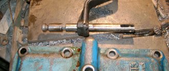
- The rod of the reversing device is equipped with a fork. It flips the direction-changing sleeve to the right in one direction, or to the left in the other direction, or to neutral. This is how commands are implemented that change the direction of movement.
- A homemade reversible gearbox is controlled using a rod lever.
Another interesting article: Main types of gearbox for walk-behind tractor
A do-it-yourself reduction unit will be considered high quality if the following factors were taken into account during its manufacture:
- rated power;
- permissible limit temperature under extreme conditions;
- rotational speed;
- permissible loads on axles and parts;
- the size of the gearbox angle;
- torque value;
- type of lubricant for rubbing parts;
- frequency of work.
If the gearbox for a mini tractor is used incorrectly, it may fail. The following reasons may lead to this:
- excessive load causes a large release of heat, this leads to overheating of the shaft and transmission parts, teeth may break, shocks will be heard in the chassis, and uncontrollability will appear when the speed decreases;
- incorrect choice of gear ratio;
- neglect of routine repairs, which includes a preliminary inspection of the engine and main components.
Thus, since the walk-behind tractor has a certain speed range, it is therefore important that when switching them, the functionality of all components is maintained.
A self-made gearbox ensures an increase in power with a sharp drop in speed to a minimum value.
The lowering unit must necessarily complement the design of the machine, since it is used to cultivate the ground, remove snow, leaves, grass, and various materials.
Manufacturing of a reversible gearbox
If you want to build a unit at your own discretion, then you cannot do without a borrowed housing. It is impossible to do it yourself outside of factory conditions. The material used is cast iron or aluminum alloy. The body is produced using special equipment. To make a reversible gearbox at home, you need to start with the housing. If it was not possible to select from other mechanisms, then it can be built from a gas pipe with thick walls with an outer diameter of 2.73 cm. Internal components: axles, gears. They must withstand the loads to which the homemade reverse gearbox will be subjected. Regarding seals, bearings, fuses, it is recommended to select them based on the design.
A homemade reverse unit can actually be assembled from the elements that make up the main gear on a used GAZ-69 car. Hubs, bushings for reverse, sprockets, rod, fork are machined from metal. 45 steel is suitable for this. Finished parts must be hardened. You should be very careful in the manufacture of cams on the hubs, as well as reversible bushings, since they will be subject to increased dynamic loads. The drive and driven gears must be isolated from each other by a gasket, the thickness of which can be adjusted to the degree of their pressing.
How to make a winch from a starter
Let's take the Zhiguli starter as the initial donor. It is quite reliable and at the same time has a compact size. Another advantage of this choice is that a VAZ starter can be found almost for free at any dismantling of domestic cars.
The drawing shows the device and components of the starter. In the upper part there is a retractor relay with power contacts. They can be used if large loads on the winch are expected. On the left is the bendix mechanism, which must be removed along with the cone housing.
Since we are talking about a compact, low-power mechanism, it makes no sense to make a gearbox for a winch from a flywheel gear. It is enough to pick up a unit from a large drill. Finding one will also not be difficult, since there are more tools with a burnt out motor at flea markets than with a broken gearbox.
There are no special requirements for the gearbox, the main thing is that the diameters are more or less suitable.
For our adaptation, of course, we need to reduce the speed.
We separate the Bendix housing from the winch, and we are left with only an electric motor with a rotor shaft. The coupling of the gearbox shaft with the mating part of the starter motor is done locally. There are many ways - from banal electric welding to making a transition coupling with cotter pins.
If it is necessary to increase the gear ratio, you can use a starter with a planetary gearbox. Adapting it to your design is not much more difficult than connecting the shafts directly, and the useful power of the winch will increase significantly.
To protect the operator from rotating parts, the space between the gearbox and the engine is closed with a pipe of a suitable size, possibly made of plastic. The casing does not carry a power load, so the gearbox housing must be firmly connected to the motor housing.
Simple threaded studs will not work here; you need to work on the design. In this case, the housing must be dismountable for periodic inspection and maintenance (cleaning, lubrication) of the motor bearings and gearbox mechanism.
Next we make the drum. You can make it at home from a piece of steel pipe with a diameter of 120-180 mm and sheet iron 2-3 mm thick.
We cut out round cheeks and weld them to the pipe. In the center of each sidewall we drill a hole for the power shaft.
The power shaft with the working gear in this design is borrowed from a decommissioned electrified valve mechanism, which is used on gas and oil pipelines. Be sure to use a standard pair of gears, otherwise it will be difficult to pair the main sprocket with the gearbox output.
All elements must be securely welded together; any weakness will sooner or later crack, and the structure will fall apart at the most crucial moment.
A channel or steel strip with a thickness of at least 5 mm is used as a frame. The winch elements should not have any play relative to each other.
The side walls are made of sheet iron 3-5 mm. Thinner sheets may become deformed when the cable is pulled under load.
The most important part is attaching the drum axis. For this, powerful bearings with podiums from some mechanism from the times of the USSR were used. You can find such spare parts at scrap metal collection points or in the workshops of abandoned factories.
The podiums are welded to the side walls. If you managed to find only bearings, weld the outer race. Nothing will happen to the rolling mechanism; the bearings simply cannot be replaced.
We attach the gearbox to the frame so that its gear meshes with the power gear on the drum shaft. We remind you that initially we had a set of a shaft and a set of gears. We install an eyelet between the walls - a leash for the cable.
We connect the gearbox with the electric motor from the starter, put the winch in good shape: we clean the welds with a grinder, remove rust, and cover the tool with paint.
The design has been tested to lift weights up to 200 kg. In this version, two gearboxes are used - from an electric drill and a homemade one from a gas electric valve. It feels like there will be enough traction for another 100-150kg.
If you install a starter with its own planetary gearbox, the gear ratio of which will be added to the two existing ones, the capabilities of the device will double.
The video shows an example of a winch using a starter.
How to use the device?
Be sure to provide for the possibility of reversing the power supply to the winch. Reverse is necessary in such devices. Since this is a regular car electric motor, changing “+” to “-” will change the direction of rotation of the shaft.
Let the power starter be the old one, from the solenoid relay. And the start buttons come from ancient electromechanical devices. The button block can provide for polarity reversal.
If the winch is used in a car, do not connect it to the standard battery with the engine turned off. With a good load, you will drain the battery in 10-15 minutes.
The dimensions allow the winch to be placed on the bumper of an SUV prepared for off-road use.
