Power steering MTZ-82 (power steering) is installed on agricultural machinery in order to reduce the effort the tractor driver makes to turn the steering wheel. At the same time, the maneuverability of the tractor increases under any conditions in which it is necessary to work.
When moving the power steering of the tractor, the MTZ is connected and functions not only when the steering wheel is turned, but also under the influence of the movement of the front wheels, which oscillate due to uneven ground. At the same time, the MTZ power steering affects the other side, relative to the rotation of the wheels. This has a good effect on the movement of agricultural machinery in a straight line and significantly reduces the transmission of vibrations and other adverse effects from the front wheels.
What is power steering MTZ
The Minsk Tractor Plant has provided all its Belarus equipment with a hydraulic booster, primarily in order to make it easier for tractor drivers to control a tractor equipped with attachments. Indeed, under its influence, a double load is placed on the front wheels, and the driver has to exert the maximum amount of effort to control such a heavy machine. The MTZ power steering has a built-in hydraulic system, the design of which includes the following main elements:
- Distributor.
- Metering and power cylinder pump.
- Rear axle differential lock sensor.
The design of the MTZ power steering includes the following structural elements:
- The housing, which contains the container where the required oil will be stored, and the bases to which the parts will be attached.
- A pump designed to move oil in a hydraulic circuit.
- A sector attached to a rotary shaft that constantly comes into contact with the steering element.
- Rotary shaft, which has 3 points of support. With its help, the turning movement is transmitted to the bipod, which, in turn, is connected to the front wheels of the vehicle.
- The rack comes into contact with the moving sector and transmits piston movement to it.
- A spool attached between 3 pairs of sliders, which are held in place by special springs. This element is attached to the end of the steering column worm.
- A filter designed to clean the oil moving in a hydraulic installation.
- A safety valve provided in the design to prevent the pressure of the desired fluid from increasing to an unacceptable level.
The automatic locking system, on which a number of other elements are located (spool valve, flywheel, sensor, valve and dipstick), is needed to lock the rear axle differential. The key operating principle of power steering is increasing hydraulic force with increasing resistance when turning agricultural machinery. The resistance that is generated when the car turns causes a displacement of the steering column from the axis of the worm. Because of this, the springs of the sliders are compressed. As soon as this resistance exceeds the compression force of all springs, the spool moves and allows specialized fluid to enter one of the containers of the power cylinder.
The oil, in turn, changes the position of the piston, and its force, with the help of a rack, enters the gear sector, with the help of which the rotary shaft rotates. When the resistance that arose during the turn subsides, the springs return to their original, straightened position, and the spool moves into place, thereby preventing more working fluid from flowing into the cylinder. If a situation arises in which the turning resistance does not increase enough to exceed the compression force of the springs, then the power steering does not begin to function.
Do-it-yourself repair of power steering tractor T-40
The price for a T-40 power steering ranges from 10-13 thousand rubles; a comprehensive repair will cost about the same amount. Therefore, making repairs yourself and performing maintenance yourself is the best option for the tractor owner. Thanks to the video, you can learn in more detail about the repair of the T-40 steering column.
Disassembly and assembly
Disassembling the T-40 power steering is performed according to the following instructions:
- when disassembling the piston assembly, press the pin located in the rear nut all the way;
- the nut must be unscrewed and removed together with the spring washer;
- The screw is pushed towards the front cover, then the spool with springs and stops is removed.
Assembly is performed in reverse order, but the following tips should be followed:
- make sure that when assembling the pin is on the side of the back cover;
- the spool must move freely, without friction or jamming;
- before assembling the power steering, the component parts are washed with clean diesel fuel;
- The spool also needs to be washed and treated with diesel oil.
How to properly install the power steering of the T-40 tractor
When installing and assembling the T-40 power steering, special attention should be paid to the position of the screw, since it is equipped with a multi-start thread. You will need to select the correct position for its entry, leaving a gap of 1 mm between the piston and the nut (preferably without deviations)
To ensure proper installation, it is recommended to follow the following instructions:
- together with the cover and the front nut, the screw is inserted into the piston so that in the operating position the thickening of the tooth faces the bottom and the pin is in front;
- The position of the pin is fixed and the rear nut is screwed. The nuts are fastened with a slight tension so that the depth from the end hole of the rod does not exceed 17 cm. If you tighten it more, the pin may not fit into the right place. A click will indicate that the pin has entered correctly.
Power steering on MTZ-80: device, malfunctions and methods of elimination
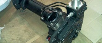
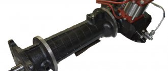
On Minsk MTZ-80 (82), equipped with a D-240 engine, a 70-3400020 power steering is installed, which is produced by the Bobruisk Plant of Tractor Parts and Assemblies (BZTDiA).
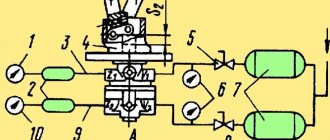
Let's look at the diagram 70-3400020 in section. The unit is placed in a housing (2) made of cast iron, which is installed on the machine frame between the front wall of the hood and the diesel engine radiator. It houses the main steering mechanism - these are a connected worm (5) and a sector (4); as well as hydraulic units of the system: hydraulic pump NSh-10-L-U GOST 8753-71, power cylinder, safety valve, spool valve, and hydraulic tank.
If there is a malfunction in the power steering system for any reason, stiff steering occurs. Let's look at the main types of power steering faults, how to fix them and improve them yourself.
- If foam forms in the system, the reasons may be the following:
- due to the fact that the fluid level in the power steering tank is low (then you should check the level and add fluid if necessary);
- air has entered it (inspect the suction pipeline (20) in order to identify places where air is leaking, carry out repairs, put washers on the connection, replace the seals).
How to improve the power steering with your own hands by placing washers under the spool is shown in the video below.
Not available:
| № | Part code | Name | Part Information |
| 50-3406011-A | Valve cover assembly | Quantity per For all modifications 1 Model 50 Group Steering control Subgroup 3406 Serial part number 011 Additionally Interchangeable with a part previously released under the same number | Not available |
| 50-3406015-A | Power steering distributor assembly | Quantity per For all modifications 1 Model 50 Group Steering control Subgroup 3406 Serial part number 015 Additionally Interchangeable with a part previously released under the same number | Not available |
| 50-3406020 | Distributor housing assembly (for MTZ-82/82L tractors) | Quantity per For all modifications 1 Model 50 Group Steering control Subgroup 3406 Part number 020 | Not available |
| 50-3406024 | Lid | Quantity per For all modifications 1 Note Aluminum alloy AL Model 50 Group Steering control Subgroup 3406 Part number 024 | Not available |
| 50-3406039 | screw | Quantity per For all modifications 1 Note Steel 12 Model 50 Group Steering control Subgroup 3406 Part number 039 | Not available |
| 50-3406019-B | Crawler | Quantity per For all modifications 6 Note Steel 45X Model 50 Group Steering control Subgroup 3406 Serial part number 019 Additionally Interchangeable with a part released earlier under the same number | Not available |
| 50-3406033 | Spring | Quantity per For all modifications 1 Note Wire I-2.5 Model 50 Group Steering control Subgroup 3406 Part number 033 | Not available |
| Ring-020-025-30-1-5-GOST-9833-73 | Ring 020-025-30-1-5 GOST 9833-73 | Quantity per For all modifications 2 | Not available |
| Bolt-M8-6gх50-88-35-019-GOST-7795-70 | Bolt М8-6gх50.88.35.019 GOST 7795-70 | Quantity per For all modifications 2 | Not available |
| Washer-8T-65G-06-OST-37-001-115-75 | Washer 8T 65G 06 OST 37.001.115-75 | Quantity per For all modifications 2 | Not available |
| 50-3406017-B | Lid | Quantity per For all modifications 1 Unit weight, kg 3.59 Note Cast iron SCh21-40 Model 50 Group Steering control Subgroup 3406 Serial part number 017 Additionally Interchangeable with a part previously released under the same number | Not available |
| Cork-KG1/8″-OST-23-1-117-83 | Plug KG1/8″ OST 23.1.117-83 | Quantity per For all modifications 1 | Not available |
| Bolt-М8-6gх25-88-35-019-GOST-7796-70 | Bolt M8-6gх25.88.35.019 GOST 7796-70 | Quantity per For all modifications 1 | Not available |
| Ring-017-022-30-2-2-GOST-9833-73 | Ring 017-022-30-2-2 GOST 9833-73 | Quantity per For all modifications 1 | Not available |
| N-036-04-003 | Union | Quantity per For all modifications 2 | Not available |
| Р75-В-028А | Pad | Quantity per For all modifications 1 | Not available |
| 50-3406028 | Nest | Quantity per For all modifications 1 Model 50 Group Steering control Subgroup 3406 Part number 028 | Not available |
| Sharik-B-III-5.556-mm-R-GOST-3722-60 | Ball B III 5.556 mm R GOST 3722-60 | Quantity per For all modifications 1 | Not available |
| 50-3406027 | Guide | Quantity per For all modifications 1 Note Steel 45X Model 50 Group Steering control Subgroup 3406 Part number 027 | Not available |
| 50-3406026 | Spring | Quantity per For all modifications 1 Note Wire II-1.8 Model 50 Group Steering control Subgroup 3406 Part number 026 | Not available |
| Р40/75-0808049-А | Screw | Quantity per For all modifications 1 Note Steel 45 Model P40/75 Subgroup 0808 Serial part number 049 Additionally Interchangeable with a part released earlier under the same number | Not available |
| Ring-018-022-25-2-2-GOST-9833-73 | Ring 018-022-25-2-2 GOST 9833-73 | Quantity per For all modifications 2 Note Rubber 7-B-14-1 | Not available |
| R75-058B | screw | Quantity per For all modifications 1 Note Steel 45 | Not available |
| R75-051B | Cap | Quantity per For all modifications 1 Note Steel 45 | Not available |
| Bearing-205K-GOST-8338-75 | Bearing 205K GOST 8338-75 | Quantity per For all modifications 2 | Not available |
| 36-1702358 | Spring ring | Quantity per For all modifications 1 Model 36 Group Gearbox Subgroup Gear shift mechanism Part serial number 358 | Not available |
| 50-3405036 | Ring | Quantity per For all modifications 1 Note Rubber compound IRP-Model 50 Group Steering control Subgroup Power steering cylinder Part serial number 036 | Not available |
| 50-3405026 | Sleeve | Quantity for all modifications 1 Unit weight, kg 1.225 Note Cast iron SCh15-32 Model 50 Group Steering control Subgroup Power steering cylinder Serial part number 026 | Not available |
| Washer-10-01-019-GOST-11371-78 | Washer 10.01.019 GOST 11371-78 | Quantity per For all modifications 1 | Not available |
| Washer-10OT-65G-06-GOST-6402-70 | Washer 10OT 65G 06 GOST 6402-70 | Quantity per For all modifications 5 | Not available |
| Bolt-М10-6gх30-88-35-019-GOST-7796-70 | Bolt М10-6gх30.88.35.019 GOST 7796-70 | Quantity per For all modifications 1 | Not available |
| Cuff-2-25x42-1-GOST-8752-70 | Cuff 2-25x42-1 GOST 8752-70 | Quantity per For all modifications 1 | Not available |
| 50-3406034 | Worm | Quantity per For all modifications 1 Note Steel 20ХНР Model 50 Group Steering control Subgroup 3406 Part number 034 | Not available |
| 50-3406037 | Thrust washer | Quantity per For all modifications 1 Note Steel 10 Model 50 Group Steering control Subgroup 3406 Part number 037 | Not available |
| Bearing-958705 | Bearing 958705 | Quantity per For all modifications 2 Coating without coating | Not available |
| 50-3406018-B | Spool | Quantity per For all modifications 1 Note Steel ШХ-15 Model 50 Group Steering control Subgroup 3406 Serial part number 018 Additionally Interchangeable with parts released earlier under the same number | Not available |
| Ring-085-090-30-1-4-GOST-9833-73 | Ring 085-090-30-1-4 GOST 9833-73 | Quantity per For all modifications 2 | Not available |
| 50-3406016-B | Frame | Quantity per For all modifications 1 Unit weight, kg 1.053 Note Cast iron SCh18-36 Model 50 Group Steering control Subgroup 3406 Serial part number 016 Additionally Interchangeable with parts released earlier under the same number | Not available |
| 50-3406041 | Washer | Quantity per For all modifications 1 Note Steel 40X Model 50 Group Steering control Subgroup 3406 Part number 041 | Not available |
| Cotter pin-4x36-001-GOST-397-66 | Cotter pin 4x36-001 GOST 397-66 | Quantity per For all modifications 1 | Not available |
| Bolt-М10-6gх100-88-35-019-GOST-7795-70 | Bolt M10-6gх100.88.35.019 GOST 7795-70 | Quantity per For all modifications 4 | Not available |
How to adjust the hydraulic booster
The main malfunctions of the power steering relate primarily to the rack, sector and worm. In addition, alteration of the MTZ power steering may be required if the tightness of its design has been compromised or the safety valve has become unusable. If, when diagnosing the components of the power steering, any malfunctions were identified, it is necessary to figure out whether the usual adjustment of the MTZ power steering can be carried out or whether the adjustment operations will be insufficient and more thorough repairs will be required.
To fix a breakdown that affects, for example, a distributor, it will be necessary to remove the hydraulic booster from the agricultural machinery and disassemble it. In the future, an examination will be carried out and the necessary parts will be replaced.
Before adjusting or repairing the hydraulic booster, it is necessary to drain the working fluid and loosen the rotary shaft nut.
The converted installation must be reinstalled on the tractor with the utmost care - pay attention to the degree of tightening of the nuts, make sure that the turning shaft marks and other elements fall into place.
With an adjusted hydraulic booster you can “go” quite far. However, when carrying out work, you should be careful and follow the basic rules for carrying out such work. Otherwise, you may break an important part. If you do not have the necessary skills, it is better to entrust adjustment issues to specialists.