The axles of the GAZ 66 truck are very popular among off-road vehicle enthusiasts. It is thanks to their design that the legendary all-wheel drive vehicle has fantastic cross-country ability. Even without any tuning of the chassis, the GAZ 66 has a ground clearance of 315 mm and is capable of fording up to 0.8 m.
Crossing the river in a GAZ 66 truck
Characteristics
The high cross-country ability of the “sixty-six” is achieved mainly due to the design features of the transmission and suspension, and is obtained due to:
This is what classic gas 66 looks like
- The presence of both drive axles in the transmission;
- The presence of a reducing speed in the transfer case;
- The tracks of the rear and front axles are almost identical in size;
- By installing one ramp on the axles;
- Features of tire manufacturing.
The front axle on the GAZ 66 off-road truck is disengaged; CV joints (CV joints) are used to turn the wheels. On the rear axle there are axle shafts that are driven by a gearbox.
As a rule, the differentials of both axles 66 are self-locking, that is, the movement of the differential gears is blocked, thereby achieving synchronous movement of the wheels. The blocking is controlled from the vehicle's cabin. You cannot drive on hard-paved roads with a locked differential. Moreover, it is impossible to operate a machine with a lock at high speed.
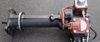
This is what the rear axle looks like for a GAZ 6 truck.
The torque of the engine crankshaft is high and can, under heavy load, damage the cam differential gears or break the axle shaft.
Blocking on the front axle reduces vehicle controllability. Both GAZ 66 axles have an identical main gear, and the design of the differentials is also no different. We can say that the gearbox assemblies are the same, the only difference is in the oil drain ring, which is placed on the drive gear of the main gear. Bridges have the following characteristics:
- The gear ratio of the main pair is 6.83;
- Front axle track – 1.8 m;
- Rear axle track – 1.75 m;
- Weight of the front axle assembly – 350 kg;
- Weight of the rear axle assembly – 270 kg;
- The type of gears of the main pair is bevel, hypoid type.
All-terrain vehicles
A list of all-terrain vehicles using GAZ-66 axles is at the end of the article.
Front and rear drive axles of GAZ-66
The main gear and differential of the front and rear axles of the GAZ-66 are the same. The main gear (reducer) of the GAZ-66 is hypoid type: the displacement of the drive gear axis is directed downwards and is equal to 32 mm. The front and rear axle beams are box-section. The design of the front axle steering knuckle is shown in Fig. 1.
Fig.1. Drive to the front wheels of the GAZ-66 car
1—wheel; 2 — oil seal block; 3—king pin; 4—steering knuckle lever, 5—bushing; b - oil seal; 7—ball joint; 8—leading fist; 9—trunnion; 10—brake; 31—drive flange; 12—air supply channel; 13 — flange cover; 14, 15 — bearing nuts; 16 — lock washer; 17—footboard; 18 — hub; 19—driven fist; 20—air shut-off valve
In order to remove the GAZ-66 constant velocity joint from the steering knuckle, you should:
- Raise the front axle of the GAZ-66 on a jack, put stands for safety and remove the wheel, having first disconnected the air supply tube to the air valve, the protective casing of the tube and the stand. Unscrew the three screws securing the brake drum and remove it;
- Unscrew the tube from the flexible hose passing through the brake shield. Unscrew twelve nuts and remove hub 18 together with axle 9 without disassembling the bearings and hub seals, then remove the hinge.
If necessary, disassemble the GAZ-66 CV joint in the following order:
- Mark with paint or chalk the relative positions of the hinge knuckles.
- Place the GAZ-66 CV joint vertically with the short fist up, spread the fists, turn the central ball with the flat towards one of the drive balls, bend the drive fist, while one of the drive balls can be removed from the hinge. The remaining balls, after the first one is removed, are removed freely.
After selecting new repair balls of increased size or replacing one of the knuckles, assemble the hinge in the following order:
- Secure the long fist in a vice (fist up).
- Place the central ball in the recess of the leading fist so that the flat of the ball is directed to the side.
- Place a short fist on the center ball.
- Turning the GAZ-66 fist to the side, install three drive balls alternately in the grooves of the fists.
- Having spread the fists of the GAZ-66 hinge to the maximum angle and turning the central ball with the flat towards the groove of the fourth drive ball, insert this ball into the groove so that it passes by the flat.
When installing the GAZ-66 CV joint in place, it is necessary to lubricate the ball joint bushing and the knuckle journal under the bushing. The longitudinal movements of the constant velocity joint are limited by thrust washers, one of which is installed in the ball joint, and the other in the axle.
Rear and front axles of GAZ-66 - malfunctions and their elimination
Increased noise
- Incorrect adjustment of the gear engagement of the GAZ-66 axle gearbox by contact - Make the adjustment
- increased lateral clearance in the engagement of the drive and driven gears as a result of wear of their teeth or bearings - Replace the gears of the GAZ-66 gearbox. The position of the gears should not be adjusted to compensate for wear.
- misalignment of bearings due to wear – Replace worn bearings
Large angular play of the drive gear of the GAZ-66 axle reducer
- wear of the splines of the axle shafts, constant velocity joints - Replace worn parts
- increased lateral clearance in the gear mesh of the GAZ-66 gearbox due to tooth wear - Replace the gearbox gears
- wear or misalignment of bearings - Adjust or replace worn bearings
Oil leakage through the cuffs of the drive gear and hubs, as well as along the connector plane of the GAZ-66 gearbox housing
Wear of the flange seals and wheel hubs, the propeller shaft mounting flange, loosening of the bolts securing the GAZ-66 gearbox housing - Replace worn parts, tighten the bolts
Unsatisfactory lubrication - Replace the main gear (gearbox) gears, fill in hypoid lubricant of the required quality
Gearbox of the front and rear axle GAZ-66
The design of the gearbox of the front and rear axles of the GAZ-66 is shown in Fig. 2. Adjustment of the preload of bevel bearings 6 and 16 of the gearbox drive gear is made by ring 15.
Boring of the sockets in the crankcase and the covers of 24 differential bearings, as well as threading, is done as an assembly, therefore, after disassembly, the covers must be placed in their original places, which is ensured by the presence of identical markings on each side of the crankcase and the mating bearing cover.
The preload of the differential bearings of the GAZ-66 axles is regulated by nuts 20. The same nuts regulate the position of the driven gear, that is, the amount of lateral clearance, as well as the size and location of the contact patch in the gear mesh.
Fig.2. Gearbox of the front and rear axle GAZ-66
1—oil receiving tube; 2—upper channel; 3—lower channel; 4—stop screw; 5—adjusting shims; 6, 16 and 29—taper bearings; 7—cover; 8—nut; 9—drive gear; 10—flange; 11—cuff; 12 - oil removal ring; 13 and 31—bolts; 14 - coupling; 15—adjusting ring; 17 — filler plug; 18—roller bearing; 19—crankcase; 20—nut; 21—axle shaft; 22—differential cup; 23—locking plate; 24—cover; 25—rusk; 26—driven gear; 27—outer sprocket; 28—separator; 30—internal sprocket
The gearbox differential of the GAZ-66 axles is cam-type, with twenty-four radial cotters 25 installed in the separator holes in two rows in a checkerboard pattern. The outer differential sprocket has six cams evenly spaced around its circumference, and the inner sprocket has two rows of cams (six each), arranged in a checkerboard pattern.
The main gear and differential of the GAZ-66 gearbox are installed in a separate housing 19, which is freely inserted into the hole in the bridge beam and secured with bolts 31.
To ensure a forced supply of lubricant to the bearings of the drive gear of the front and rear axles, an oil receiving tube 1 is installed in the gearbox housing, which, in contact with the driven gear, collects the oil entrained by it. From tube 1 through the upper channel 2, oil is supplied to the bearings and discharged through the lower channel 3.
The gearboxes of the front and rear axles of the GAZ-66 are distinguished by different oil removal rings installed on the splines of the drive gear. The front axle ring is marked P, the rear axle ring is not marked.
To distinguish the GAZ-66 gearboxes, there is a P marking on the drive gear flange of the front axle (there is no marking on the drive gear flange of the rear axle). To prevent pressure build-up inside the crankcase when heated during operation, a breather is installed in the crankcase.
Steering knuckles and axles of the front axle GAZ-66 (Catalog 1996)
- 201416-P8 Bolt M6-6gx12
- 201540-P29 Bolt M12-6gx30 OST 37.001.123-96
- 23707 Bearing
- 250688-P29 Nut M10x1-6N
- 252134-P29 Washer 6
- 252137-P29 Washer 12
- 252138-P8 Washer 14.2
- 252156-P29 Washer 10
- 264020-P29 Oiler 1.3 Ts6.hr GOST 19853-74
- 291798-P2 Hairpin M10x(1.5-Sp/1-4N)x30 OST 37.001.180-96
- 291849-P8 Hairpin M12x(1.75-Sp/1.25-Sp1)x35 OST 37.001.180-96
- 291882-P8 Hairpin M14x1.5-Sph35
- 292832-P8 Nut SpM 12x1.25
- 292855-P8 Nut M14x1.5 Sp
- 294990-P Pin 6x11
- 45 9346 1173 Bolt М14Х1.5-4hх75
- 51-2401050 Lock washer for rear wheel hub bearing nut
- 51-2403042-B Expansion bushing for rear axle axle stud
- 53-2401052-01 Bearing nut
- 53-2401053-01 Nut
- 53-2401054-01 Rear wheel hub bearing nut with pin assembly
- 53-2403048 Axle shaft gasket
- 63-2304084 Steering knuckle housing gasket
- 66-02-2304010 Right rotary knuckle assembly
- 66-02-2304011 Left rotary knuckle assembly
- 66-02-2304040-B Right steering knuckle housing
- 66-02-2304041-B Left steering knuckle housing
- 66-02-2304060 Right steering knuckle joint assembly
- 66-02-2304061 Left steering knuckle joint assembly
- 66-02-2304080 Steering knuckle axle assembly
- 66-02-2304091 Front wheel hub drive flange
- 66-2304012 Ball joint assembly
- 66-2304024 Thrust washer for steering knuckle joint
- 66-2304026 Ball joint gasket
- 66-2304028 Gasket adjusting thickness 0.10 mm
- 66-2304029 Adjusting gasket thickness. 0.15 mm
- 66-2304035 Steering knuckle lever
- 66-2304037 Upper steering knuckle pin cover
- 66-2304038-A Bottom steering knuckle pin trim
- 66-2304051-B Steering knuckle oil seal housing
- 66-2304052 Internal sealing ring for steering knuckle oil seal
- 66-2304053 Steering knuckle oil seal spring
- 66-2304054 Spacer ring for steering knuckle oil seal
- 66-2304055 Outer sealing ring for steering knuckle oil seal
- 66-2304056-B Outer race for steering knuckle oil seal
- 66-2304057 Steering knuckle oil seal gasket
- 66-2304071 Front drive axle joint seal assembly
- 66-3506095 Front axle flexible hose mounting bracket, right
- 66-3506096 Front axle flexible hose mounting bracket, left
Rear axle 66-02-2400012, axle shafts and axles of the rear axle GAZ-66 (Catalogue 1996)
- 201419-P8 Bolt M6-6gx18
- 201496-P8 Bolt M10-6gx22
- 201499-P29 Bolt M10-6gx30 OST 37.001.123-96
- 250612-P29 Nut M10-6N OST 37.001.124-93
- 250688-P29 Nut M10x1-6N
- 252137-P8 Spring washer 12
- 252138-P8 Washer 14.2
- 252156-P29 Washer 10
- 258288-P Cotter pin wire 1.6x350
- 262517-P Stopper KG 2″
- 262521-P Plug KG1″
- 290606-P Bolt M8-6gх14
- 291151-P Bolt M16-4hx105
- 291554-P29 Bolt M12x1.25-6gx38
- 291557-P29 Bolt M12-4hx45
- 291798-P2 Hairpin M10x(1.5-Sp/1-4N)x30 OST 37.001.180-96
- 291882-P8 Hairpin M14x1.5-Sph35
- 292855-P8 Nut M14x1.5 Sp
- 292977-P29 Nut M30x1.5-5N6N
- 294990-P Pin 6x11
- 296576-P29 Plug KG1/2″
- 298430-ПУ Breather assembly
- 51-2401034-A3 Winch gear worm oil seal assembly
- 51-2401050 Lock washer for rear wheel hub bearing nut
- 53-2401052-01 Bearing nut
- 53-2401053-01 Nut
- 53-2401054-01 Rear wheel hub bearing nut with pin assembly
- 53-2402012-10 Rear axle gear housing with bearing caps assembled
- 53-2402045 Rear axle gear housing gasket
- 53-2402046 Gasket 0.10 mm thick
- 53-2402047 Adjusting gasket 0.25 mm thick
- 53-2402048 Adjusting gasket
- 53-2402078-10 Adjusting screw for the driven gear stop of the main pair of the rear axle assembly
- 53-2402086-A Tube
- 53-2402087 Locking plate
- 53-2402088 Oil pickup tube plate
- 53-2402089 Oil pickup tube spring
- 53-2403040 Differential bearing nut
- 53-2403044 Locking plate for differential bearing nut
- 53-2403048 Axle shaft gasket
- 63-2304084 Steering knuckle housing gasket
- 66-02-2400012 Rear axle with brakes and hubs assembled
- 66-02-2401005-20 Rear axle housing assembly
- 66-02-2401005-21 Carter assembly
- 66-02-2401051 Rear axle axle
- 66-02-2401067 Rear axle axle
- 66-02-2403070-01 Rear axle axle shaft
- 66-2402010 Rear axle gearbox assembly
Construction of bridges
Rear axle
The GAZ 66 rear axle consists of the following main parts:
- Carter (“stocking”);
- Gearbox assembly;
- Two axle shafts;
- Two trunnions.
The crankcase is a long elongated body (of the “stocking” type) with a thickening and a hole in the middle for installing the gearbox. In turn, the gearbox is the main driving part of the bridge; it changes the gear ratio and forces the wheels to spin at the speed necessary for optimal vehicle movement.
The gearbox consists of the following main parts:
- frame;
- final drive gears;
- differential assembly;
- bearings.
Front axle
The front axle gearbox is no different from the rear gearbox, but the housing has structural differences. Instead of axle shafts, constant velocity joints (CV joints) are installed on the front axle. The CV joint itself consists of several parts:
- driven fist;
- leading fist;
- balls (4 pcs.).
Parameters and weight of GAZ-66 bridges
Speaking about the technical characteristics of the GAZ-66 axles, which provide good cross-country ability for the truck, it should be noted the design features of the vehicle’s suspension and transmission:
- The presence of several driving axles at the same time.
- The presence of slopes on each axis.
- Almost identical dimensions of the rear and front axles.
- Possibility of using reduced speed via transfer case.
This design itself can be turned off, and CV joints are used to turn the wheels. But at the rear there are axle shafts, which are provided with movement through a gearbox. In this case, there is a self-locking differential, which is ensured by blocking the movement of gears. This allows you to create synchronized movement of all drive wheels. This process is controlled by the driver from the cab. However, in this form the car cannot move on roads equipped with dense surfaces, or at high speeds. This is due to the fact that the torque is too high and can even break the axle shaft. The bridges themselves have the following parameters:
- Track size front and rear: 1.8/1.75 m.
- Weight of the front and rear structure when assembled: 350/270 kg.
- The gear ratio is 6.83.
- The gears of the main pairs are bevel.
The design used at the rear of the GAZ-66 is in many ways similar to that used on the GAZ-53. However, the latter lacks the ability to lock the differential, but this cannot be seen in the photo of the axles.
Bridge Maintenance
Axle maintenance consists of periodically checking the presence of oil in the crankcase, lubricating CV joints, checking the tightness of connections, and visually inspecting components for oil leaks. It is recommended to change the oil in axles every 50-70 thousand kilometers. But it must be taken into account that the GAZ 66 is often used in difficult road conditions.
If the car has to cross a ford, then if the bridges are poorly sealed, water can get into the oil. Then an oil change will be necessary.
Axles 66 are filled with transmission lubricant type TSP-14gip. If necessary, you can use other brands of gear oil, for example, TAp-15V, TAD-17i, TEp-15. When operating a vehicle at temperatures below - 35ºC, it is recommended to add 10-15% of diesel fuel from the total volume of the filling tank to the lubricant.
Replacing the front axle with gas 66
The filling capacity of the front axle is 7.7 liters, 6.4 liters must be filled into the rear axle.
Rear axle malfunctions
The main failures of drive axles include increased noise during movement and oil leaks.
Repair of the rear axle on a gas 66 truck
Oil leakage can occur for the following reasons:
- The seals of the axle shafts and the axle gearbox shank are torn or have lost their elasticity. The oil seal will also leak if the spring on it flies off;
- The fastening bolts on the bridges become loose;
- The gasket loses its tightness.
The cause of the noise is most often the final drive, but there may be other causes. Causes of howling or noise in bridges:
- The gap between a pair of final drive gears is incorrectly adjusted;
- Axle bearings are worn out;
- The axle gearbox shank nut has become loose;
- The gears of the main pair are worn out;
- The differential gears or axles are worn.
Gear wear can occur due to insufficient oil in the crankcase or its complete absence.
If there is no oil (it has leaked), then such a bridge will not travel much and will jam after a few tens of kilometers. But this is already an emergency situation - almost any driver immediately pays attention to the increased noise (howling) that appears in the car. And a bridge without lubrication will make a lot of noise before it jams. Therefore, driving with the noise of bridges is unacceptable. If it is impossible to figure out the problem yourself, the driver should contact specialists to identify the cause of the bridge malfunction.
Malfunctions of constant velocity joints
CV joint malfunctions are easily determined. When turning the wheels at speed, clicks appear in the front axle. When the hinges are heavily worn, clicks may also be heard when the wheels are turned in place. You should not allow the joint to wear out completely, as this may cause the car to lose control, which will affect traffic safety.
This is what a gas 66 CV joint looks like
How to adjust the rear gearbox gas 66
This bolt is not entirely adjustable.
It is more persistent than adjustable. In a bevel gear, a force acts in engagement that can be decomposed into three forces: - tangential - the only useful one, directed tangentially to both the shank (drive gear) and the gear on the differential block, this force transmits rotation. in addition, two parasitic forces arise - axial (directed along the axis) on the shank, it compresses the shank shaft along the axis), it is also radial on the driven wheel (directed from the point of engagement to the axis) - axial on the driven wheel, it is also radial on shank. Since the parasitic forces are not applied strictly along the axes of rotation of the gears, both axial and radial forces not only compress the shafts, but also bend them. The shank is mounted on three bearings, the bearing closest to the differential block perceives only axial forces and serves to ensure that the shank is between the supports, and not on the console, which bends (breaking the engagement) much more strongly. the axial force on the driven wheel is trying to bend the thick shaft in the form of a differential housing, the shaft is sooooo thick for such a force and the engagement is not broken. the axial force on the driven wheel tries to bend the wheel away from the engagement point, disrupting engagement adjustment. When driving on a good road, the forces in the engagement are small (in high gears) and the driven wheel deflects little. In low gears, the forces in the engagement increase so much that they noticeably bend the crown of the gear wheel away from the engagement point. But it’s this stubborn bolt that prevents it from bending too much. The bent crown of the driven wheel rests against it and the geometry in the engagement is much less disrupted. The result is small losses due to additional friction in the contact of the thrust washer on the bolt with the wheel crown, but the gears themselves last much longer.
This bolt is not entirely adjustable. It is more persistent than adjustable. But it’s this stubborn bolt that prevents it from bending too much. The bent crown of the driven wheel rests against it and the geometry in the engagement is much less disrupted. The result is small losses due to additional friction in the contact of the thrust washer on the bolt with the wheel crown, but the gears themselves last much longer.
This means that if the gear ratio of the GP is smaller, and therefore the driven gear is smaller, the shoulder is smaller, the bend is smaller. The GP of a “military” bridge “digests” a larger moment simply structurally.
That's how I came to this myself. But its name “regulatory” was confusing. Thank you for confirming my suspicions. It just seems to me that the “bending” of the driven gear occurs not just at peak loads on the adjusted pair, but when the preload in the differential bearings decreases over time, the acting forces decrease and the driven wheel is retracted, choosing this gap that appears in the bearings. Not certainly in that way. When a gap appears in the bearings, the differential block begins to move both along the axis and perpendicular to it, and the bolt only holds the axial movement. (perpendicular to the axis, the block walks parallel to the sliding plane of the bolt) And - moreover. When play appears, it is not the “remainder” of the axial force of the driven wheel that begins to act on this bolt; a huge part of this force is transferred to the bearing by the “elasticity” of the crown. During normal adjustment, a relatively small force is applied to the bolt itself. When play appears, the ENTIRE FORCE is in full effect. And she is quite big. And this bolt cannot withstand even several hundred meters.
If I have time tomorrow, I’ll estimate the magnitude of this force.
Source
Installation of 66 axles on other car models
Many people want to install bridges that increase the vehicle's cross-country ability. Another question is how expedient their installation is, and how the replacement will affect the technical characteristics of gas 66. Due to the fact that the units have considerable weight, their use on machines of smaller dimensions will negatively affect the strength of the supporting structure. For example, when installing axles 66 on a UAZ vehicle, the frame is unlikely to withstand the load. Even the factory GAZ 66 frame often bursts from the load, and it has to be welded periodically.
Most often, bridges are used to assemble various homemade machines. Usually the chassis is taken as a basis and left unchanged, but the cabin and body are subject to deep modernization. Homemade design allows you to realize your wildest fantasies. Of course, first of all, the engine and gearbox are changed to gas 66, and more powerful wheels are used to increase cross-country ability. All-terrain vehicles and tractors are assembled on the GAZ 66 basis.
Benefits of all-wheel drive
All-wheel drive on the GAZ-66 makes it possible to drive a truck to overcome not only easy, but also difficult off-road conditions. There is virtually no risk of getting into an unpleasant situation when the car’s wheels become immobilized. “Shishiga” is capable of overcoming rough terrain and shallow rivers, and performing various maneuvers (the truck is indeed quite maneuverable). Excellent balancing helps distribute the load on both axles, and low maintenance costs make the car even more practical. Military and civilian drivers who have driven the Shishka a lot have talked and still talk about the car’s incredible cross-country ability. This is also facilitated by excellent geometry (approach angle is 35 and departure angle is 32 degrees, minimum ground clearance is 315 mm.) The geometry is successfully combined with weight distribution (especially of a loaded vehicle) and good traction capabilities of the engine, which produces maximum torque already at 2000 crankshaft revolutions per minute .
GAZ-66
GAZ-66: summer version
edit this post
