Design and adjustment of the steering control of the T-40 tractor
The steering wheels are rotated using the steering (Fig. 40).
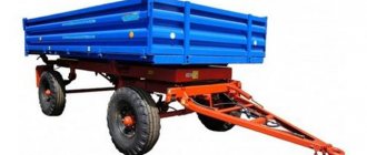
The steering of the T-40 tractor consists of a steering column, a steering wheel with a shaft and universal joints, and a hydraulic booster with a bipod.
Rice. 40. Steering of the T-40 tractor
1 - bipod; 2 — bracket; 3 — hydraulic booster; 4 — wedge assembly; 5 — cardan assembly; 6 — cardan shaft assembly; 7 — steering column; 8 - shaft; 9 — steering wheel; 10 - nut; 11 - spring washer
When the steering wheel rotates, the torque created by the driver is transmitted through the steering shaft, cardan shafts and cardan shaft to the hydraulic booster 9, which increases it by turning the shaft with bipod 1 in one direction or the other.
The hydraulic booster of the T-40 tractor is designed to reduce the force on the steering wheel when turning the tractor. It is located under the hood in the front of the tractor and mounted on the front beam of the frame.
Fig.41. Power steering (power steering) of the T-40 tractor
1 — bipod shaft; 2 — front cover; 3, 5 - nuts; 4 - ball bearing; 6 — front nut; 7 - spring washer; 8—seal; 9 - piston; 10 - body; 11 — top cover of the housing; 12, 23 — adjusting screws; 13, 22 — cap nuts; 14 - pin; 15 — power steering screw; 16 — back cover; 17 — rear nut; 18 — emphasis; 19 — spring; 20 — golden spring; 21 - spool; 24 - safety valve; 25, 26 — traffic jams
The power steering hydraulic booster of the T-40 tractor (Fig. 41) consists of a housing, a piston 9, a screw 15, a distribution device, a bipod shaft 1, front 2 and rear 16 covers.
A piston 9 is inserted into the body, which has a through hole for installing a screw 15. The screw has a left-hand four-start trapezoidal thread, onto which nuts are screwed - front 6 and rear 17.
Both nuts are secured against turning by pins 14. The rear pin, installed in the holes of the piston and rear nut, is pressed by a spring 19.
According to operating conditions, screw 15 of the hydraulic booster of the T40 tractor should not have axial movements. Therefore, bearing 4 is secured to the screw by a slotted nut 3, secured with a cotter pin, and in the cover by a nut 5.
The switchgear includes a hydraulically controlled spool 21, springs 20, stops 18, front 6 and rear nuts 17 and piston 9.
Piston 9 has three teeth that engage with the teeth of the sector of the shaft 1 of the bipod. During assembly, the middle tooth of the piston 9 is installed in the middle cavity of the sector.
When the T-40 tractor is operating, the oil flow supplied by pump 11 (Fig. 42) of the hydraulic system is divided into two branches: to the separate hydraulic system and to the hydraulic booster. This division is carried out by a flow division valve.
Rice. 42. Scheme of operation of the power steering of the T40 tractor
1 - nut; 2 — bipod shaft; 3 — piston, 4 — screw; 5 — power steering housing; 6 - spool; 7 - safety valve; 8 - filter; 9 — hydraulic tank; 10 - flow valve; 11 — hydraulic pump
The throttle opening of the flow valve spool is designed for a flow rate of 0.17–0.2 l/s (10–13 l/min) of oil required for the operation of the hydraulic booster.
With an increase in pressure in the power steering of the T-40 tractor, the spool moves down and throttles the output from the valve to the mounted system. When a load is created in the mounted system, the spool moves upward and reduces the flow output from the valve to the hydraulic booster.
With simultaneous load on both branches, the spool occupies the same middle position as in the absence of loads.
When the steering wheel rotates, both nuts move relative to the piston in such a way that one of them approaches the end of the piston and blocks the drain holes, and the other, moving away from the corresponding end, opens the drain holes. The oil flow, which was previously divided in half and passed through both cavities, in this case is divided in proportion to the flow sections.
The passage of different amounts of working fluid through the cavities is accompanied by a pressure difference, as a result of which spool 6 moves towards low pressure and closes the hole through which the oil enters the cavity with open drain holes.
In the cavity where the drain holes are closed with a nut, the pressure increases and piston 9 (see Fig. 65) moves as long as the driver rotates the steering wheel.
When the steering wheel is rotated in the other direction, the power steering of the T-40 tractor works in a similar way.
To limit the compression of the springs 20 and prevent their breakage, stops 18 are installed. During rotation, the nut approaching the end of the piston deforms the spring washer 7, as a result of which the force on the steering wheel increases.
Spring washers 7 simulate the load on the guide wheels.
When the pressure increases above 8.5+1 MPa (85+1 kgf/cm2) at an oil temperature of 15–80 °C, the oil squeezes out the ball of safety valve 7 (see Fig. 42) and drains into tank 9.
On the T40 ANM tractor, the safety valve is adjusted to a pressure of 11–11.5 MPa (110–115 kgf/cm2) at an oil temperature of 30–50 °C.
To disassemble the piston assembly, insert pin 14 (see Fig. 41) into the rear nut, unscrew nut 17 (see Fig. 41) and remove it together with spring washer 7, push hydraulic booster screw 15 towards the front cover 2 and remove the spool 21 with springs 20 and stops 18.
Reassemble the assembly in reverse order. The spring-loaded pin should be on the rear cover side. Before assembly, all parts are washed in clean diesel fuel, and spool 21 is lubricated with engine oil. The spool must move without jamming under the influence of gravity.
Screw 15 has a multi-start thread. Therefore, for the correct installation of the rear nut 17, select the appropriate approach in which the total gap between the nuts 6 and 17 and the piston 9 is equal to 1.0 ± 0.1 mm. For this:
— insert the screw assembly with the front nut and front cover into the piston from the chamfer side into a hole with a diameter of 30 mm, while simultaneously putting the nut on the pin pre-installed in the piston;
- install the spring and the second pin on the other side of the piston and, noticing the position of the pin in the piston, screw in the rear nut. In this case, if the hole for the pin of a nut screwed all the way does not coincide with the location of the pin by more than 90°, the nut is unscrewed and turned to the side by the angle of mismatch (i.e., the nut is placed on a different thread start);
Device, diagrams, repair
T-40 tractor hydraulic booster (power steering): design and repair
Power steering on the T-40 tractor to reduce the force on the steering wheel used by the tractor driver when making turns. The power steering is located in the front engine compartment of the tractor and is mounted on the front frame bar.
Power steering device
The hydraulic booster consists of a housing, a distributor, a piston, a screw, a bipod shaft, and rear and front covers. The housing contains a piston equipped with a through hole for installing a screw. The screw has a left-handed four-start trapezoidal thread onto which the rear and front nuts are screwed. Both nuts are secured with pins to prevent them from turning. The rear pin, installed in the holes of the rear nut and piston, is pressed by a spring. According to operating conditions, the power steering screw should not have axial movements. As a result, the bearing is fixed on the screw with a slotted nut, locked with a pin.
The switchgear kit includes: a hydraulically controlled spool, stops, piston, springs, rear and front nuts.
The piston has three teeth that engage with the teeth of the bipod shaft. During assembly, the middle tooth of the piston is inserted into the middle cavity of the sector. The gap in the engagement of the sector with the piston is adjusted using a special adjusting screw.
The device of the hydraulic booster of the T-40 tractor: 1 - bipod shaft; 2 — front cover; 3, 5 - nuts; 4 - ball bearing; 6 — front nut; 7 - spring washer; 5 - seal; 9 - piston; 10 - body; 11 — top cover of the housing; 12, 23 — adjusting screws; 13, 22 — cap nuts; 14 - pin; 15 — power steering screw; 16 — back cover; 17 — rear nut; 18 — emphasis; 19 — spring; 20 — spool spring; 21 - spool; 24 - safety valve; 25, 26 - traffic jams.
Operating principle
When the tractor is operating, the oil flow supplied from the hydraulic system using a pump is divided into two branches: to the hydraulic booster and to the separate hydraulic system. This division of the oil flow is carried out by a division valve. The throttle opening of the flow valve spool bypasses 10-12 liters of oil per minute, which is necessary for the functioning of the power steering of the T-40 tractor.
As the pressure in the hydraulic booster increases, the spool moves down and throttles the output from the valve to the linkage system. In the event of a load created in the mounted system, the spool moves upward and throttles the output from the flow valve to the hydraulic booster. If there is a simultaneous load on both branches, the spool takes a neutral position.
When the tractor steering wheel rotates, both nuts move relative to the piston so that one of them approaches the end part of the piston and throttles the drain hole; the other one moves away from the end of the piston, opening the drain hole. The oil flow, previously split in half and passing through both cavities, will now flow into the cavity with the open drain hole.
In a cavity with a closed drain hole, the pressure increases while moving the piston. The piston will move exactly as much as the tractor driver rotates the tractor steering wheel. When the rotation of the steering wheel stops, the nut will detach from the piston and open the drain hole, after which the pressure in both cavities will stabilize and the spool will take a neutral position.
In order to limit compression and increase the service life of the springs, stops are installed in them. When turning, one of the nuts deforms the spring washer, and the greater the resistance on the front wheels, the greater the force on the steering wheel. In this case, the spring nuts act as a load simulator on the front wheels. On the T-40 ANM tractor, the safety valve is adjusted to a pressure of 110-115 kgf/cm².
Power steering diagram of the T-40 tractor: 1 - nut; 2 — bipod shaft; 3 — piston, 4 — screw; 5 — power steering housing; 6 - spool; 7 - safety valve; 8 - filter; 9 — hydraulic tank; 10 - flow valve; 11 — hydraulic system pump.
Power steering malfunctions
1. The flow valve spool is jammed - raise and lower the rear linkage mechanism several times. If this does not help, then disassemble and wash the valve in diesel fuel.
2. Abnormal toe-in of the front wheels - set the recommended toe-in of the idler wheels (0-4 mm).
3. The bearing to the front cover is not tightened. The violation can be detected by stopping the tractor and turning the steering wheel while the engine is running. If the screw moves back and forth, it means the bearing is not tightened - disassemble the hydraulic booster, tighten the nuts until they stop and lock with the screw.
Repair and adjustment of the T-40 hydraulic booster
When disassembling the piston, press the pin into the rear nut, unscrew the nut and remove it together with the spring washer; push the power steering screw towards the front cover and pull out the spool with stops and springs.
Assembly occurs in reverse order. The spring-loaded pin should be located on the rear cover side. Before assembly, wash all parts in clean diesel fuel and lubricate the spool with oil. The lubricated spool should move without jamming under its own weight.
Power steering of tractor T-40
As we described above, the main purpose of the power steering is to reduce the turning force of the tractor driver’s steering wheel for the required maneuver; it also transmits one-way rotation in the required direction from the steering wheel to the steering wheels. This significantly relieves the wheel itself from impacts when driving on an uneven surface, increasing safety and driving style.
Important! The movement of the tractor will be maintained even if the tires are damaged.
Diagram and principle of operation of the tractor hydraulic booster
Below we will provide a control diagram for the T-40 power steering, and below it we will give its explanation
The power steering is located in the front part under the hood and its main components are: housing (3), bipod (1), front (27) and rear (21) covers. It also includes spool 926), stops (25) and nuts (16,20).
On the one hand, the piston is made in the form of a rack with three teeth of varying thickness. They are engaged with the teeth of the part (1), which also have different thicknesses. During assembly, the middle tooth is placed in a similar cavity. And the gaps are adjusted using a screw (position 4).
Below we will give a diagram of the flow of the tractor hydraulic system and also give its description.
When the T-40 tractor is operating, the oil flow, which is directed by the pump (11), is divided into two branches: to the hydraulic booster and to the separation and aggregate system. The division occurs due to the valve, the nominal volume for which it is designed is 10-11 l/min.
If the pressure in the power steering increases, the spool moves down and thereby throttles the oil output from the valve to the mounted system. If pressure is created in the mounted system, the spool moves downward, thereby throttling the oil output to the hydraulic booster.
Important! If the load goes in two directions at once, then the spool takes the standard position.
At the moment the steering wheel rotates, two nuts move relative to the piston, so that one of them approaches its end, and the second moves away from the advising end.
In this case, the flow of oil, which was previously divided in two, will pass only through one direction, where the drain hole is open. This is how its proportional division occurs relative to the sections.
With a change in the direction of rotation of the steering wheel, the operation of the power steering is similar to the previous one.
In order to limit compression and premature failure of the spring (24), a stop (25) is installed in it. It turns out that when turning one of the nuts deforms the spring washer. The force on the steering wheel itself will be greater as the resistance of the steering wheels increases.
If the pressure in the system increases to more than 120 kgf/cm2, the oil will squeeze out the valve ball (7) and bypass the amplifier and enter the drain tank (9)
Design and principle of operation of the power steering of the T-40 tractor
Power steering is one of the elements of the T-40 steering structure. It is located under the hood, closer to the front. The main components that you will have to deal with during repair or maintenance are: covers (front and rear), stops, nuts, bipod, spool.
The power steering of the T-40 tractor operates on the principle of a piston. The oil is dosed by a spool located inside the piston.
Power steering
Algorithm of operation of the T-40 power steering:
- hydraulic fluid is supplied from a gear pump;
- The spool valve distributes the flow to the rear linkage and tractor steering;
- pressure is supplied to the T-40 steering column.
When the steering wheel rotates, two nuts in relation to the piston move as follows: one moves towards the end, and the other moves away. Therefore, the oil flow always moves in one direction, tending to the open drain hole.
Assembly and disassembly of power steering T-40
When disassembling the piston assembly, it is necessary to recess the pin (11), which is located in the rear nut, unscrew the nut (20), then remove it together with the spring washer (19). Next, push the tractor power steering screw (22) towards the front cover and remove the spool (26) along with the stops and springs (24,25).
Assembly must be done in reverse order. Only the pin should be on the side of the back cover.
Remember! Before assembly, you need to wash all mechanisms in clean diesel fuel, and lubricate the spool with diesel oil.
In this case, it (the spool) should move without any jamming.
Correct installation
The screw (item 22) has a multi-start thread. Because of this, in order to carry out the assembly correctly, you need to select the recommended approach, and leave a total gap between the nut (16,20) and the piston (18) of 1 mm (permissible deviation no more than 0.1 mm).
1. Place the screw together with the front nut and cover in the piston, so that the pin is in front or the thickening of its tooth in the working position is directed downward. To do this, turn the piston until the hole of the nut and the pin match.
2. Next, mark the position of the pin in the piston and screw on the rear nut.
3. The nuts must be installed with some interference on the washers, tighten (20), and hold in the end hole of the rod with a diameter of 8 mm at a depth of about 17 mm along with a screwdriver. The pin should click into the hole. It is impossible to install the rod at a deeper depth, because it will prevent the pin from falling into place.
Do-it-yourself repair of power steering tractor T-40
The price for a T-40 power steering ranges from 10-13 thousand rubles; a comprehensive repair will cost about the same amount. Therefore, making repairs yourself and performing maintenance yourself is the best option for the tractor owner. Thanks to the video, you can learn in more detail about the repair of the T-40 steering column.
Disassembly and assembly
Disassembling the T-40 power steering is performed according to the following instructions:
- when disassembling the piston assembly, press the pin located in the rear nut all the way;
- the nut must be unscrewed and removed together with the spring washer;
- The screw is pushed towards the front cover, then the spool with springs and stops is removed.
Repair and maintenance of power steering
The T-40 hydraulic booster maintenance procedure itself includes: searching for and eliminating various oil leaks through gaskets, seals and various connections, adding oil to the required levels and washing the filter elements. Typically, hydraulic booster maintenance is done every 100 engine hours.
Remember! The power steering valve is adjusted at the factory and a seal is installed. The seal can be broken only in case of significant violation of the parameters.
Before adjusting the valve, it is necessary to connect a pressure gauge to the discharge line. We unscrew the plug (10) and place a stop between the bipod and the beam.
Then unscrew the safety valve locknut and cap. We start the engine and set the crankshaft speed to the maximum possible speed. By turning the bipod towards the stop, using the steering wheel, we adjust the oil flow pressure through the valve in the range (80 kgf/cm2 at 10-35°C and 75 kgf/cm2 at temperatures above 35°C). After adjustment, we put everything in place. Remember, with the engine and hydraulic pump running, the steering play should not be more than 20°. If the amount of play is greater, then it is necessary to tighten the connections of the shaft and bipod and check the location of the engagement of the shaft sector with the teeth. If necessary, replace them.
Adjusting the side clearance and engagement of the shaft teeth is done as follows:
1. Unscrew the nut (6), hold the screw (4) and unscrew the lock nut. 2. Screw the screw (4) into the cap 2 turns, then hold it and tighten the locknut and cap.
Lubrication of cardan crosspieces, need to be lubricated every 100 hours of tractor operation. This is done by injecting grease with a hand syringe until lubricant forms in the gaps.
Steering column T 40
Steering is one of the most important mechanisms in any driven vehicle. It is he who is “responsible” for turning the guide wheels and, therefore, for all maneuvers of the tractor. It is very important to ensure that it is in good working order and accurately responds to the operator’s manipulations. The steering of the T-40 tractor consists of several elements: a steering column and a wheel located in the cabin, as well as a shaft and universal joints. To facilitate control, the T-40 is equipped with a power steering system - a hydraulic booster with a bipod.
Related Posts
Why on Mtz 80, nsh 10 was covered on gur? How many splines are there on the pump shaft?
Question from a subscriber: Good day. Mtz 80, covered nsh 10 on gur. Can you please tell me how many splines are on the pump shaft?
Tractor t 150k. Why does the steering wheel refuse to turn or go after a couple of hours of work? I changed the pump, washed the tank and the mesh.
Hello guys, everyone. Tractor t150k. The driver refuses. After a couple of hours of work. Don't turn, don't go. I changed the pump, washed the tank and the mesh. Where to dig next? Tell me please
Why at T 40 am. Power steering not working?
Hello everyone. T 40 am. It’s as if the power steering is not working. What is the reason, maybe someone has encountered it. Thank you.
Why does the T40 tractor constantly tear off the clutch bolts? What bolt can I replace it with?
Hello everyone. On the T40 tractor, the clutch bolts constantly come off, who replaces them with what alternative bolts? Relatives constantly break the thread, the head, or the bolt itself. What bolt can I replace it with? They say the bolt from the head of the classic engine is suitable, but I compared the length of the bolts from the new original ones, the Zhiguli ones seem short.
Good day guys.. A friend can’t figure out the T40 tractor. I took the device and installed new injectors on the stand, but it didn’t work. The pump is also new, the hoses are new. What else could it be? Tell me, please.
Tractor T40. Why is oil leaking from under the head?
Question: [id232460791|Denis Semenov] Hello, the T40 tractor is throwing oil out from under the head, tell me what to do?
Why doesn't the right brake work? The pedal goes to the floor freely, the discs have been changed, the adjustment is almost to the end of the bolt.
Why doesn't the vom turn off? It turns when the tractor moves. And while the tractor is standing, the plow does not turn. What could it be? Tractor T 40
Good day. The vom stopped turning off. It turns when the tractor moves. And while the tractor is standing, the plow does not turn. What could it be? Has anyone encountered this? Tractor t 40
Steering column design
The steering column of the T 40 tractor consists of the following elements:
- bipod;
- bracket;
- hydraulic booster (located under the hood in the front of the tractor);
- wedge;
- cardan;
- cardan shaft;
- steering column;
- shaft;
- steering wheel;
- screw;
- spring washer.
Spring washers exert load on the idler wheels. When the steering wheel rotates, pressure increases in the piston cavity. To prevent excessive compression of the springs, stops are provided. When turning the nut, you act on the spring washer, which increases the force on the steering wheel.
The hydraulic booster on the T-40 consists of a housing, a piston, a screw, a distributor, a bipod shaft, and front and rear covers. The T 40 power steering circuit is presented in any operating device.
Power steering tractor T 40
Operating principle:
- The driver rotates the steering wheel, thereby generating torque.
- From the steering wheel, rotation is transmitted to the steering shaft and then to the cardan shafts and their shafts.
- The T 40 power steering perceives the rotation and strengthens it, turning the shaft with the bipod in the proper direction.
- The T-40 is equipped with a piston-type hydraulic booster. The hydraulic booster is lubricated through the throttle hole of the valve spool. When the tractor is operating, the oil flow is directed to the hydraulic booster and to the separate hydraulic system. A special flow valve is installed for this purpose. If the pressure in the power steering increases, the spool moves down, which increases oil flow.
- When a load is created in the mounted system, the spool moves upward, thereby reducing the oil flow to the hydraulic booster.
Related Posts
Why at T 40 am. Power steering not working?
Hello everyone. T 40 am. It’s as if the power steering is not working. What is the reason, maybe someone has encountered it. Thank you.
Which is better for the T-40 AM mower, rotary or segmented?
Good afternoon, can you recommend a T-40 AM hay mower? Rotary or segmental? Thanks in advance.
Can the T-40 AM carry such a weapon?
Brothers tractor drivers! Please tell me if the T 40 AM can have such a weapon
Need reviews. Which tractor is better to buy for yourself: T-40 AM or MTZ 82?
Need feedback, please help. Which tractor is better to buy for yourself: T-40 AM or MTZ 82? Photo to attract attention. Thanks in advance for your opinions!
T-40am
Why does the front axle jam in 5th and 6th gear on the T-40 AM tractor. The right side is pulling!
Hello, friends! Please tell me who may have had the problem that the front axle on the T 40 am tractor jammed. Previously, this happened when you were driving in 6th gear, but now it starts to jam in 5th! The right side is pulling! [id373578351|Ilgiz Yakupov]
How to install camber and toe on T-40 am
How to install camber and toe on T-40 am
What kind of oil should I put in the T-40 for the winter?
Good morning. Guys, what kind of oil do you use for the winter? T-40
T-40am. Why does the steering wheel turn to the left, but not to the right?
Guys, the problem is this: on the T40am the steering behaves strangely, initially everything was fine. Now the steering wheel turns to the left, but not to the right. I can’t understand anything. Thanks in advance for the advice.
Tractor T-40 am. Why did the pressure in the tractor hydraulic system disappear?
Source
Tell me, I changed the pump on the T 40; the linkage works well and the steering wheel is tight. Was it the other way around before?
COMMENTS (12)
Power steering repair
Repairing a power steering is a complex procedure. It is no coincidence that on new tractors the power steering valve is equipped with a seal - intervention can lead to serious damage. However, on older tractors, repairs are usually carried out with your own hands, power steering T 40. Before you start adjusting the valve, you need to adjust the oil pressure in the system. To do this, you need to connect a pressure gauge to the discharge hose. After unscrewing the locknut, start the engine at maximum crankshaft speed. Oil pressure is adjusted by turning the bipod. Next, it is important to check the steering play. The maximum value with the engine and hydraulic pump running is 20°. If there are deviations, they must be eliminated by tightening the shaft and bipod connections. In addition, it is necessary to carefully examine the place where the shaft sector engages with the teeth and, if they are damaged, replace them.
Another important procedure is adjusting the side clearance and engagement of the shaft teeth. Produced in several stages:
- Unscrew the nut and locknut.
- Screw the screw into the cover two turns.
- Tighten the locknut and cap.
Dismantling and assembling the steering control
Unlike power steering disassembly, column repair is accessible to novice mechanics. To disassemble the piston, press the pin into the rear nut, after which it will be possible to unscrew and remove the nut and spring washer. Then you need to push out the power steering screw and remove the spool. Reassemble the assembly in reverse order. All parts are first washed in clean diesel fuel, and the spool is lubricated with engine oil. Before starting work, it is recommended to read the instructions and watch training videos.
Installation Rules
Many tractor owners, having disassembled the unit, decide to convert it into a metering pump. This makes management even easier. Installing a double pump allows you to separately connect the tractor linkage, separately - the hydraulic cylinder and the steering metering unit.
Power steering diagram of the T 40 tractor
The complexity of such a modification lies in the fact that today there are no standardized mounting brackets for the metering pump and hydraulic cylinder. As a rule, the dispenser is placed closer to the cabin, at the exit point of the steering shaft cardan. You will need to make a homemade bracket and weld it above the fourth cylinder. In this case, it will be convenient to connect the hoses with fittings at 90 degrees.
Adjustment
The unit is checked and adjusted every 100 operating hours. It is necessary to inspect all parts and mechanisms for defects. Check:
- reliability of threaded connections;
- general condition of the column;
- presence of cracks, chips, rust.
Lubrication is carried out at the same time. Recommended lubricants are listed in the instruction manual. For example, cardan crosspieces are lubricated by injecting grease with a hand-held syringe until lubricant forms in the gaps.
Related Posts
The NSh-32 hydraulic pump hums, does not lift, and oil oozes. What is the problem?
Please tell me, maybe someone has experienced: when lifting the rear linkage, the hydraulic pump NSh-32 (universal) makes a loud noise, and oil oozes from the seals. The lift itself is very weak, it feels like there is not enough oil.
Why does the steering stick? Recently I changed the pipe, the left king pin, a new pump, and the right king pin.
t 150 Why doesn't it lift the hitch, only at revs? Before this, my partner’s hitch cylinder failed (the cuff on the piston was torn). Repaired.
Hi all. Guys! Such a problem. At t 150 I stopped lifting the hitch. Only at revs. Before this, during the night at my partner’s, the hitch cylinder failed (the cuff on the piston was torn). They sorted it out and collected it, but it barely lifts it. If you hold the lever up and slow down, it starts to go down. You put the hitch in neutral and it holds. That is, the cylinder was assembled normally. We disassembled the valve and cleaned everything clearly. What could it be? Before repairing the cylinder, I raised it at low speeds. Have a nice day admin!
The T-25 tractor stood for about a month. I started it, but the rear linkage does not respond to the lever. All oils are fine. What is the reason?
I arrived from the field at T25 and everything was fine. The tractor sat for about a month. I started it, but the rear linkage does not respond to the lever. All oils are fine. What could be the reason?
MTZ 82p loader, Why digs weakly, especially when it’s hot. To replace NSh 100 with axial piston ones. Are any adapters needed?
Guys, happy holiday to all, Fisherman's Day. I have a question: I bought an ex-MTZ 82p loader, it digs poorly, especially when it’s hot. I want to change the NSh 100 to axial piston ones. Are any adapters needed or not? Thank you.
Mtz 1221 Why did the linkage and levers stop lifting? At high speeds it lifts itself, but the load is no longer there. I changed the pump, the valve on the distributor is clean.
Hello people This is the problem with MTZ 1221. The linkage and levers have stopped lifting. At high speeds it lifts itself, but the load is no longer there. I replaced the pump 3 times for 32 nsh. All to no avail, nothing helped. What could it be? The valve is clean on the distributor.
If you open the left side cover with the gearbox, will it be possible to diagnose the bearings and gear with the reverse gear shaft? Mtz-82
Good day everyone)) happy holiday! Question: if you open the left side cover with the gearbox, will it be possible to diagnose the bearings and gear with the reverse gear shaft? Mtz-82
Source