- home
- Media center
- Articles
- Tractor clutch principle
Menu
- News
- Articles
- Video materials
- Photo materials
- Publication in the media
- 3D tour
18.07.2020
Tractors operate by installing friction clutches. The latter, from a physical point of view, use friction forces that arise during the interaction of a number of structural parts to transmit torque.
Features of the tractor main clutch
The clutch is designed to solve a number of problems, so it can have different design features. Let's list:
- for starting off in a smooth mode;
- disconnection of the connection between the engine and transmission during gear shifting;
- transmission protection when using different tractor operating modes.
All special equipment is divided into subtypes, which are equipped with one or several clutches. The main one is the clutch, located immediately behind the diesel engine. Included in the transmission design. The operating principle is based on the diesel engine being supported on the crankshaft. This is done through a ball bearing, which is pressed into the end part.
If the driven disk is placed next to the flywheel, then rotation will not occur. But when you move it to the left and increase the pressure towards the flywheel, the friction forces will increase, due to which the pressure on the disk will increase. All this in total constitutes the principle of operation of the tractor’s clutch, since it organizes a smooth connection of the shafts.
The design and principle of operation of the clutch
Everyone probably knows about such a car component as the clutch. And many people know that it is needed to be able to safely change gears even when the car starts moving. But how does the clutch work, this rather capricious unit to master in a driving school?
Earlier, in the article “Car Clutch,” we talked about the purpose and classification of clutches. Now let's take a closer look at the design and operating principle of the most common type of clutch - a dry friction single-plate clutch.
Mechanisms for the main clutch
To ensure the correct operating principle of the tractor's clutch, mechanisms with various design features are used. But at the same time, the device is saved based on the operation scheme described above.
The tractor clutch contains a base, which is a special casing. Inside it there is a drive disk and compression springs. The casing is fixed to the surface of the flywheel. Between the last and the driving disk, a driven disk is installed, which is made of a thin steel profile. On both sides of the latter there are asbestos linings, to which materials have been added to increase the binding effect.
The linings in the clutch device are responsible for resistance to high temperature effects that appear as a result of disc slipping during the on and off processes. At the same time, they have a high coefficient of friction.
The driven disk hub is located on shaft splines. The disk itself is pressed against the flywheel due to springs, which are placed with a tight stop in relation to the casing. The latter are inserted inside special glasses. The implementation of a tight clamping effect causes frictional forces. The rotation of the flywheel produces torque, due to which friction is transferred to the driven shaft and then passes to the drive shaft.
This operating principle of the tractor clutch is frictional and corresponds to the option using a single disc. Due to this, the circuit is closed. But a format using two slave disks is also possible.
For this purpose, high-power diesel engines are installed on special equipment. Strong torques are transmitted to it, which one unit cannot achieve due to its lower strength. Such a friction clutch will be double-disc and also closed.
The control mechanism of the entire clutch device consists of connecting the levers, fork and pedal. The system includes a movable clutch and a thrust ball bearing with release levers. In addition, it is connected directly to the master disk.
The clutch is released by pressing the pedal. This is accompanied by the clutch moving to the left, which causes the levers to automatically press. Rotating the parts on the axes will move the drive disk in the desired direction. This stops the transmission of torque.
To engage the tractor clutch, the pedal causes the action of the springs, which helps the flywheel again perform the desired movement and press the driven disk.
Disc slipping causes an increase in temperature, so slow clutch engagement is not recommended for use, as it can cause overheating and malfunctions. Accelerated or slow activation does not meet the standards for using the machine, which is 1.5-3 seconds.
Principle of operation
The principle of operation of the clutch is based on a rigid connection between the clutch driven disc and the engine flywheel due to the frictional force generated by the force created by the diaphragm spring. The clutch has two modes: “on” and “off”. Most of the time the driven disk is pressed against the flywheel. Torque from the flywheel is transmitted to the driven disk, and from it through a splined connection to the input shaft of the gearbox.
Diaphragm spring operation diagram
To disengage the clutch, the driver presses the pedal, which is connected to the fork by a mechanical or hydraulic drive. The fork moves the release bearing, which, by pressing on the ends of the petals of the diaphragm spring, stops its pressure on the pressure plate, and it, in turn, releases the driven one. At this point, the engine is disconnected from the transmission.
After engaging the desired gear in the gearbox, the driver releases the clutch pedal, the fork stops acting on the release bearing, and it stops acting on the spring. The pressure plate presses the driven one against the flywheel. The engine is connected to the transmission.
Additional mechanisms
This device format is used to obtain improved performance. The mechanisms are responsible for reducing the effort required to turn on, allow you to dampen vibrations during torsion and speed up the timely shutdown of the driven disk.
- To reduce effort. The principle of disengaging the tractor clutch is based on the action of a series of springs with high elasticity. Influencing them requires significant effort. To complete the task, amplifiers of various types are installed: based on mechanics, hydraulics or pneumatics.
- Dampening of torsional vibrations. Such processes are caused by the operation of the crankshaft, which undergoes numerous unwinding and twisting up to certain deformation values. To prevent future wear and increase service life, the connection between the discs and the hub is made by installing additional elements. They are rubber-based dampers or spring mechanisms.
- Shifting gears at the clutch is difficult due to the presence of inertial processes. To avoid its increase and extinguish, a brake setting is used.
The clutch release should be clean and the engagement should be smooth.
For shock-free gear shifting in the gearbox, the driven part of the clutch must have a small moment of inertia or a braking device that stops the driven part when the clutch is disengaged.
The clutch must be simple and reliable in operation, as well as easy to operate.
According to the principle of operation, clutches are divided into friction, hydrodynamic and electromagnetic.
In friction clutches, torque is transmitted due to the friction forces that arise when the drive and driven disks are compressed.
The hydromechanical clutch consists of two impellers with blades: pump and turbine; The pump wheel is connected to the engine shaft, the turbine wheel is connected to the drive shaft of the gearbox. The hydraulic coupling impellers are enclosed in an insulated crankcase with working fluid. When the pump wheel rotates, the working fluid is thrown onto the blades of the turbine wheel and, due to dynamic action, rotates it. Thus, when a fluid coupling operates, the connection between the driving and driven parts is carried out through a liquid; in this case, the driven turbine wheel can slide freely relative to the driving pump wheel.
A hydromechanical clutch differs from a torque converter in the absence of a reactor.
The main advantage of a fluid coupling is the extremely smooth transmission of torque (damping property). If there is a fluid coupling in the power transmission, high smoothness of starting and acceleration, movement at a reduced speed in any gear, and stopping without turning off the gear are ensured.
At the same time, the fluid coupling does not allow for complete integration of the power transmission from the engine shaft and has internal energy losses during fluid circulation.
Fluid couplings are used in combination with friction clutches.
The operation of electromagnetic clutches is based on the use of electromagnetic forces to connect the driving and driven parts. Such clutches have smooth, shock-free engagement and clear disengagement, they dampen torsional vibrations well, limit engine overload, and are simple and easy to operate.
Rice. 1. Schematic diagram of a mechanical friction clutch: 1 - drive disk; 2 — driven disk; 3 - pressure bearing; 4 - driven shaft
However, electromagnetic couplings also have significant disadvantages: a significant moment of inertia of the driven parts (electromagnets), relatively low efficiency due to energy losses for excitation, dependence on the current source, and the cost of non-ferrous metals.
Electromagnetic clutches are used on certain brands of low-power tractors.
Currently, friction clutches are predominantly used on tractors. Such couplings consist of a driving part connected to the engine flywheel; driven part connected to the gearbox; a pressure mechanism that compresses the clutch discs, and a release mechanism that relieves the compression force of the discs.
For reliable operation of the clutch, the friction torque Mm developed by it must exceed the maximum engine torque Mmmax.
Friction clutches are classified according to the following characteristics: - according to the type of pressure mechanism - permanently closed with pressure springs and non-permanently closed with a lever pressure mechanism; - by the number of slave disks - single-disk, double-disk and multi-disk; - according to the type of disc friction - dry and wet; by the number of independently acting couplings connected in one mechanism - single and double; a single clutch is used to disconnect the power transmission from the engine, a double clutch is a combination of two independently acting clutches, one of which disconnects the power transmission from the engine, and the second is designed to control the power take-off shaft.
The schematic diagram of a permanently closed clutch is shown in Figure 2, a. The driving part of this clutch consists of a clutch housing and a pressure plate connected to the flywheel.
The driven part of the clutch consists of the driven disc and the clutch shaft. In this case, the driven disk is seated on the splines of the coupling shaft.
The pressure mechanism is a spring type, the pressure springs are located in the casing and constantly act on the pressure disk.
The shutdown mechanism in the diagram is represented by a pedal with a drive to the release clutch and through it to the pressure plate.
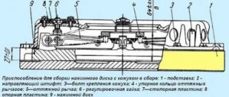
Rice. 2. Schemes of friction clutches: a - permanently closed single-plate; b - non-permanently closed two-disk; c - permanently closed two-disc; g - permanently closed double (double-flow) single-bottom; 1 - flywheel; 2 — driven disk; 3 — pressure disk; 4 — release lever; 5 — release clutch; 6 — clutch control pedal (lever); 7 — clutch shaft; 8 — pressure springs; 9 — clutch housing; 10 — release springs of the intermediate disk; 11 — intermediate disk; 12 — bolt for adjusting the movement of the intermediate disk; 13 — brake; 14 - layering; 15 — earrings; 16 — cross; 17 — pressure cams; 18 - thrust pin; 19 — bolt for adjusting the movement of the drive disk of the main clutch; 20 — power take-off shaft drive gear; 21 — tension springs of the drive disk of the main clutch; 22 — driving pressure plate of the additional clutch; 23 — driven disk of additional clutch
A permanently closed clutch works like this. While no force is applied to the pedal, the pressure springs move the pressure and driven discs towards the flywheel and tightly press the rubbing surfaces of the discs and the flywheel together. Torque from the flywheel is transmitted to the clamped driven disk 2 and from it through a splined connection to the driven shaft.
When the clutch is disengaged, a force is applied to the pedal, which is transmitted to the pressure plate. Under the influence of this force, the pressure plate is retracted, overcoming the resistance of the springs. In this case, the driven disk becomes free and gradually stops. To increase the friction force on the disks, and therefore the torque transmitted by the clutch, special friction linings with a high coefficient of friction are riveted or glued to the driven disks.
A non-permanently closed clutch, the schematic diagram of which is shown in Figure 2, b, consists of a driving part (an intermediate disk connected to the flywheel through splines or drive pins with leads), a driven part (front driven disk, pressure plate and clutch shaft), a lever-cam type pressure mechanism (cams, crosspiece, shackles) and a shutdown mechanism (lever-driven pull-off and brakes). Using a lever, this clutch can be set to one of two positions: permanently on or permanently off.
When the layer moves to the left, the force from it through the earrings is transferred to the cams. The pressure part of the cams rests on the disk and moves it along the shaft splines towards the drive disk. The latter is clamped between the front driven disc and the pressure plate. The engine torque is transmitted from the flywheel to the drive disk, and from it to the driven front and pressure disks and then to the clutch shaft.
By moving the offset to the right, the force of pressing the cams on the disk is weakened, and then completely removed. The friction force between the working surfaces of the disks is reduced to a minimum, and the transmission of torque from the drive disk to the driven disks stops. By further moving the shift to the right, the brake is activated, and the driven part of the clutch quickly stops.
Non-permanently closed clutches are used mainly on some crawler tractors.
The double-disc permanently closed clutch, the diagram of which is shown in Figure 2, c, differs from a similar single-disc clutch in its ability to transmit increased torque. This is achieved by increasing the number of friction surfaces from two to four.
The discs of this clutch are compressed by pressure springs. Torque is transmitted from the flywheel through the clutch housing, drive plates, driven plates and shaft.
By moving the release clutch to the left, the levers move the pressure plate to the left, overcoming the resistance of the springs. This releases the rear driven disk. The release springs move the intermediate drive disk to the right and thereby release the left driven disk. Thus, the clutch is disengaged.
To prevent the intermediate disk, moving to the right, from pressing the right driven disk against the driving pressure disk, the stroke of the disk is limited by a stop bolt. This ensures clean disengagement of the double-disc clutch.
The double-disk permanently closed clutch is used on trucks and tractors when it is necessary to transmit significant torque and have an increased reserve of the calculated clutch torque.
Multi-plate clutches are used in cases where, due to the limited size of the clutch, the transmission of increased torque is required (for example, control clutches for crawler tractors) or when the clutch must operate in crankcase conditions with splashed oil (for example, clutches in the crankcase of the gearbox of a power transmission for switching gears ).
Clutches in which the discs operate under dry friction conditions are called dry. They have the ability to transmit increased torque with limited disk sizes (due to the increased coefficient of friction between the disks). However, the working discs of these couplings wear out quite intensively due to dry friction.
Clutches whose discs operate under conditions of unlimited oil contact with the rubbing surfaces are called wet. Such couplings have relatively little disc wear, but also limited transmitted torque (due to a reduced friction coefficient).
Some tractors equipped with a power take-off shaft (PTO) use double (double-flow) clutches. Such a clutch consists of two independently operating clutches, one of which is the main clutch, and the second serves to control the PTO. Such clutches can be controlled by separate pedals or using a single pedal. Figure 2, d shows a diagram of a double, single-plate, permanently closed clutch, which is controlled by one pedal. This clutch works as follows.
During the first half of the pedal stroke, the release clutch, acting on the release levers, moves the PTO clutch drive pressure plate to the right. Then the driving pressure plate of the main clutch also moves to the right under the action of the release springs. The driven disk of the main clutch is released, but the PTO clutch remains engaged, since its driven disk is clamped between the drive disks and the force of the springs.
To disengage the PTO clutch, full pedal travel is required. At the same time, the left pressure plate moves to the right until its pins touch the adjusting bolts and stops. At the same time, the pressure plate continues to move to the right, overcoming the resistance of the pressure springs. At the same time, the driven disk of the PTO clutch is released, and the transmission of torque to the PTO stops.
Friction clutches operate under conditions of high torque overloads, high rotation speeds, unsteady motion and constant slipping of the discs. As a result, the friction linings are subject to significant heating and wear. The release levers and release clutch (Fig. 2, a, b and b), pressure cams and lift (Fig. 2, b) also wear out systematically. Pressure springs that heat up during operation (Fig. 2, a, c and d) gradually lose their elasticity. All this leads to disruption of the normal operation of the clutch.
The main malfunctions of friction clutches are slipping of the discs under load and insufficient release cleanliness (the clutch drives).
If the clutch does not transmit full torque (slips), then the reasons for this may be: oiling of the rubbing surfaces, weakening of the force of the pressure mechanism on the discs due to wear of the discs (friction linings), weakening of the pressure springs, lack of free play of the clutch pedal, wear of parts lever-cam pressure mechanism.
The clutch does not ensure clean disengagement due to increased free play of the pedal, warping of the discs, insufficient free play of the intermediate disc, and improper adjustment of the lever-cam pressure mechanism.
To eliminate malfunctions, the clutch clutch is adjusted and repaired.
In permanently closed clutches, during operation, the free travel of the pedal, the free travel of the intermediate disk and the moment of brake activation are regulated.
The pedal free play (usually 35...45 mm) is adjusted to ensure maximum compression force on the discs under the action of pressure springs. Correct adjustment of the pedal free play should ensure a gap between the working end of the release clutch (Fig. 2, a) and the inner ends of the release levers 4 from 2 to 4 mm. In the absence of such a gap, the release clutch rests on the levers, which hold the pressure plate 3 and thereby limit its pressure on the driven disk.
The gap between the inner ends of the release levers and the end of the release clutch is adjusted by changing the length of the clutch pedal rod.
The free play of the intermediate disc in a double-plate clutch is adjusted to ensure clean disengagement of the clutch. If the free play of the intermediate disk is insufficient, the front driven disk is not completely released when the clutch is disengaged and, therefore, continues to rotate. If there is excessive free play, the intermediate disc touches the rear driven disc and drives it.
The free play of the intermediate disk is adjusted using a thrust bolt.
To quickly stop the driven part of the clutch and the drive shaft of the gearbox for the purpose of clear and silent gear shifting, the moment of activation of the brake is adjusted to a. The brake of the driven part must be activated at the moment the clutch is completely disengaged. The brake is adjusted by changing the length of its control rod.
In non-permanently closed clutches, the compression force of the discs is controlled by a lever-cam pressure mechanism. With normal compression of the disks, the clutch does not slip or drive, and the force on the control lever is 100...150 N. The compression force of the clutch disks is regulated by changing the position of the cams relative to the pressure plate by moving the cross along the thread of the front driven disk hub.
—
The clutch allows you to quickly disconnect the engine from the power transmission (when changing gears or a short stop) and smoothly connect them, which ensures that the tractor starts slowly and gradually increases the load on the transmission parts. These clutches are called main clutches, in contrast to the clutches used in some components and mechanisms of the tractor. The main clutches are located between the engine and gearbox.
Each clutch consists of a drive and driven parts, a control mechanism and a housing. Depending on how the driving part is connected to the driven part, clutches are divided into electromagnetic, hydraulic and mechanical friction.
Friction clutches are the most widely used on tractors. And although their operating principle is the same, their design is very diverse.
According to the type of friction, clutches are divided into dry and wet, operating in oil. On domestic tractors, the main clutches are made dry, and wet ones are used in transmission mechanisms of starting engines, power take-off shaft drives and in gearboxes with on-the-fly shifting in tractors K-701, T-150K, T-150.
Based on the number of driven discs, single-disc, double-disc and multi-disc clutches are distinguished.
According to the action of the pressure device, clutches are divided into permanently closed and non-permanently closed. In permanently closed clutches, the discs are compressed by springs, and therefore, when the tractor driver does not act on the clutch pedal, the discs are in a compressed state. In non-permanently closed clutches, compression of the discs is carried out using a lever-cam mechanism, and they are used on T-100M tractors. On a number of tractors (MTZ-80, YuMZ-6L, T-40M), the engine power is divided by a clutch into two streams - the drive of the road wheels and the drive of the power take-off shaft. Such couplings are called two-flow couplings.
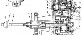
Rice. 3. Scheme of permanently closed clutches with a spring pressure mechanism: a - single-disc; b - two-disc; 1 - engine crankshaft; 2 - flywheel; 3 — driven disk with friction linings; 4 — pressure disk; 5 — clutch housing; 6 — clutch housing; 7 — release bolt; S — lever stand; 9 — release lever; 10 - layering; 11 — clutch shaft; 12 - pedal; 13 - thrust; 14 — shutdown fork; 15 — tension spring; 16 — pressure spring; 17 and 23 - guide fingers; 18 — roller bearing; 19 — release spring of the intermediate disk; 20 — adjusting bolt of the intermediate disk; 21 — pressure (drive) disk; 22 — rear driven disk; 24 — intermediate (leading) disk; 25 - front driven disk
Let's look at the diagram and design of friction clutches.
The single-plate permanently closed clutch consists of drive parts that rotate with the engine flywheel, driven parts associated with the power train, and a control mechanism.
The driving parts of the clutch are the machined surfaces of the flywheel and pressure plate. The disc is pinned to a housing that is screwed to the flywheel, so that when the flywheel rotates, the housing and pressure plate rotate as one unit. However, the disk can at the same time move along the axis.
The driven part is a disk with friction linings, which is mounted on the splines of the coupling shaft. The spline connection between the disk and shaft ensures their joint rotation and allows the disk to move in the axial direction. The driven disk is installed between the flywheel plane and the pressure drive disk. The drive disk is constantly pressed by springs installed in the casing cups, and they clamp the driven disk between the flywheel and the pressure disk. This allows torque to be transmitted from the engine to the power transmission due to friction between the disks. To disengage the clutch, it is necessary to separate the drive and driven discs. This is done using a clutch control mechanism, which consists of double-arm release levers mounted on racks fixedly attached to the casing. The short upper arms of the levers are connected to the pressure plate with bolts.
A release sits freely on the coupling shaft, which can move along the shaft and act on the inner shoulders of the release levers. The lift moves along the shaft using a double-armed fork connected by a rod to the pedal.
When you press the pedal, the fork moves the lift to the left and it presses on the inner ends of the levers. These levers, rotating around the hinges of the struts, pull the bolts and the disc to the right, while the springs are compressed even more, and the driven disc is released and the clutch is disengaged. When the pedal is released, the clutch will turn on again under the action of compressed springs, and the pedal will return to its original position under the action of the spring.
To ensure reliable friction between the disks, the driving disks are made of cast iron or plastics, and the driven disks are made of sheet steel (so that their mass and moment of energy are small) and lined with friction materials - asbestos cardboard, asbestos rubber, asbestos bakelite, ferrado, metal-ceramic linings.
When transmitting high torque, double-disc and multi-disc clutches are used.
Double-disc permanently closed clutches with spring-loaded push mechanism. In this clutch, two driving and two driven disks are installed alternately. Otherwise, the design and operation of a double-disc clutch are the same as that of a single-disc clutch, with the only difference being that when the clutch is turned off, special springs move the intermediate drive disk away from the flywheel, freeing the driven disk. The stroke of the intermediate disk is limited by an adjusting bolt, the correct adjustment of which ensures the release of the second driven disk.
Design of tractor clutches. The MTZ-80/82 tractors are equipped with a dry single-disc clutch of a permanent closed type. It is located in the dry compartment of the housing connecting the engine and gearbox; the rear power take-off shaft drive and the gearbox reduction gear are also located here.
The driving parts of the clutch are the engine flywheel, the pressure plate and the support plate. The support stamped disk is connected to the flywheel using bolts and spacer bushings. The pressure plate has three lugs that pass through slots in the support plate, to which the release levers are attached. Twelve springs are installed between the support and pressure disks.
The driven disk is made of sheet steel and lined with friction linings, connected to the hub through damper springs.
Thus, the driven disk is not connected to the hub rigidly, but through a spring device, which facilitates soft engagement of the clutch and reduces dynamic loads in the transmission. Elastic plates are placed under the friction linings of the driven disk on the pressure disk side, facilitating smooth and “soft” engagement of the clutch.
The clutch is equipped with a brake, which, when the clutch is disengaged, stops the clutch shaft and the gearbox input shaft. This makes gear shifting easier and increases gear life.
The clutch is disengaged by pressing the release bearing on the ends of the release levers, which, supported by adjusting screws in the pins of the support disk, rotate and move the pressure disk away from the driven one, disengaging the clutch. The clutch is engaged under the action of springs.
The release bearing is mounted on the offset and, together with it, moves along the shank of the bracket when turning the fork and the release shaft.
The clutch and brake control are interlocked and carried out by one pedal. When the clutch is disengaged, the fork simultaneously turns and the tap moves toward the disc. Due to the friction of the discs, the clutch disc and shaft are braked.
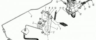
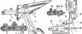
Rice. 4. Clutch and brake control mechanism: 1 - finger; 2 — pedal lever; 3 — servo spring; 4 - thrust bolt; 5 - bolt; 6 — bracket; 7 — clutch rod; 8 - threaded coupling; 9 — lever; 10 - spring; 11 — brake rod; 12 — brake lever; 13 - pedal
The control drive is equipped with a servo spring amplifier, which makes it easier for the driver to control the clutch. The servo spring rests at one end against the thrust bolt of the fixed bracket, and at the other end it is connected to the upper arm of the lever, which rotates on the pin. The lower arm of the lever is connected by a rod to the lever of the roller fork.
When the clutch is engaged (as shown in the figure), the geometric axis of the spring passes above the longitudinal axis of the three-arm lever pin, and the servo spring holds the pedal stationary. If foot pressure is applied to the pedal and the lever is rotated, the lever arm with the spring will also rotate down counterclockwise relative to the pin, and the spring will be compressed until it reaches the neutral line. As soon as the axis of the spring is below the axis of the pin, the spring, expanding, will create a force that makes it easier to disengage the clutch.
From the pedal lever, the force is transmitted through a rod to the release shaft lever, the release forks and the release bearing.
The clutch release shaft lever is connected by a spring-loaded rod to the brake control lever. This ensures the clutch locks, brakes, and is controlled by one pedal. The thrust spring facilitates smooth activation of the brakes.
Servo springs for the clutch control drive are installed on some other tractors (DT-75M, T-54V, T-40M).
Maintenance of the clutch consists of periodic lubrication, checking and tightening of threaded connections, making adjustments and troubleshooting. Every 60 hours of operation, lubricate the release bearing with solid oil, and after 240 hours, lubricate the pedal lever hub.
The main indicator of correct clutch and brake adjustment is the free play of the pedal. The free play of the pedal pad should be 40-45 mm, which corresponds to the gap between the release bearing and release levers - 3 mm.
As the friction linings wear out, the free play of the pedal decreases, so it is checked every 240 hours of operation.
Adjust the free play and length of the brake locking rod simultaneously in the following sequence: a) disconnect the brake rod from the lever; b) release the pedal from the servo spring, for which they screw the bolt into the bracket and release the bracket fastening bolt; c) by changing the length of the rod, set the free play of the pedal pad within 40-45 mm; d) turning the bracket counterclockwise around the axis, move it until it stops against the bolt and tighten the bracket fastening bolts; e) by unscrewing the thrust bolt from the bracket, return the pedal to its original position.
The length of the brake rod is adjusted by turning the brake lever counterclockwise until it stops and in this position the length of the rod is changed by connecting it to the lever. Having measured the length of the rod, disconnect it, shorten it by 7 mm and put it in place.
Rice. 5. Clutch: 1 - flywheel; 2, 15 — oilers; 3 — intermediate disk; 4 — pressure disk; 5 — release spring; 6 — driven disks; 7 - casing; 8 — release lever; 9 - fork; 10 — spring locking bolt; 11 — locking spring; 12 — adjusting nut; 13 — lever release spring; 14 - thrust ring; 16 — bearing stop; 17 — body; 18 — release bearing cup; 19 — clutch shaft; 20 — brake pad; 21 - spring; 22 — earring; 23 — spring cup; 24 — earring coupling; 25 — shutdown fork; 26 — shutdown roller; 27 — bearing of the shutdown mechanism; 28 — pressure spring; 29 — clutch shaft bearing
Before final installation of the rod, check the length of the spring; it should be 35 mm.
When assembling the coupling, the release levers are adjusted so that the distance from the point of contact of the levers with the release bearing to the end of the support disk is 12 ± 0.5 mm. The deviation from this size for individual levers should not exceed 0.3 mm.
A single-disc permanently closed clutch is also installed on T-25A1 tractors.
The T-150, T-150K tractors are equipped with a dry double-disc permanently closed clutch.
The driving parts of the coupling are the engine flywheel, which has four grooves. The spikes of the intermediate and pressure drive disks fit freely into these grooves. The pressure plate has release levers connected to the casing through forks. To install the levers in one plane and restore their position when the pad wears out, adjusting nuts are provided.
A torsional vibration damper is installed in each driven disk. The elastic element of the damper is eight springs evenly spaced around the circumference. The driven disks are clamped between the end surfaces of the flywheel and the drive disks by the force of twenty springs. Release springs are installed on both sides of the intermediate disk, which, when the clutch is disengaged, move the intermediate disk to the middle position between the flywheel and the pressure disk.
The clutch release mechanism consists of a housing with an angular contact ball bearing installed in it, a stop, a fork and a roller, four release levers with a thrust ring.
For shock-free switching of transfer case gears, a shoe brake is installed in the clutch housing. Smooth braking of the driven part of the clutch and the input shaft of the gearbox is created due to the elastic connection of the pad with the roller through a spring. The clutch is controlled using a pedal, which is connected to the right rotary lever of the roller, the release fork of the release bearing housing, through a servo device of the pneumatic servomechanism. The tracking device is connected by a hose to a pneumatic chamber, the rod of which is connected to the left rotary arm of the roller.
Rice. 6. Drive for disengaging the main clutch: 1 — tension spring; 2 — traction fork; 3 - lever; 4 - pedal; 5 - extension; 6 - traction; 7 — tracking device; 8, 29 — hoses; 9 — rear glass; 10 — release bearing housing: U — adjusting nut; 12 — locking plate: 13 — bolt; 14 - fork; 15 - axis; 16 — coupling casing; 17 — release lever; 18 — pressure disk; 19 — intermediate disk; 20 — driven disk: 21 — flywheel; 22 — bearing stop; 23 - pressure ring; 24, 26 — rotary levers; 25 — shutdown roller; 27 — pneumatic chamber bracket; 28 — pneumatic chamber; 30 — brake lever; 31 — lock bolt; 32 — axis of levers; 33 — bracket
When you press the clutch pedal, compressed air from the pneumatic system of the tractor through the hose, the valve from the suction device and the hose enters the pneumatic chamber of the servomechanism and the rod, extending, turns the release roller lever and disengages the clutch. When the clutch is turned on, air is released from the pneumatic chamber through the follower device, and the diaphragm of the pneumatic chamber, under the action of its spring, returns to its original position.
Clutch maintenance. For normal operation of the clutch, there must be a gap of 3.5-4.0 mm between the release bearing stop and the release lever ring, which contributes to a free pedal travel of 30-40 mm.
As the rubbing surfaces of the discs wear, the gap decreases, reducing the free play of the pedal. Lack of clearance or free play in the pedal causes slipping of the clutch and increased wear of the discs and release bearing.
If the pedal free travel is too large, the clutch “leads”, that is, it does not completely disengage.
Adjustment of the required gap between the release bearing stop and the ring of release levers can be carried out in two ways: by changing the length of the rod (to increase the gap, the rod is shortened and screwed in; to reduce it, it is extended) or, if the disc linings are significantly worn, by restoring the original position of the release levers, for which: a ) loosen the bolts attaching the locking plates and unscrew each adjusting nut half a turn. In this case, the gap between the bearing stop and the release lever ring increases to 11 - 13 mm; b) increasing the length of the rod, adjust the free play of the release bearing housing (gap 3.5-4 mm) and lock the nuts with plates, tightening the bolts c) check the uniformity of the gap and the simultaneous contact of the release levers and the ring when the clutch is turned off; d) check the stroke of the release bearing housing, which should be within 21-22 mm when the pedal stroke is 150-160 mm. At the same time as adjusting the clutch, check the brake and, if necessary, adjust the brake.
The operation of the clutch control drive is checked at an air pressure in the pneumatic system of at least 5 kgf/cm2. Every 240 hours of operation, lubricate the clutch shaft bearing and the release mechanism bearing through the oiler on the engine flywheel and the oiler on the bearing housing.
While the engine is running, do not keep your foot on the clutch pedal. This leads to failure of the pressure bearing and wear of the disc linings.
The clutch and engine are balanced as an assembly. Therefore, to maintain balancing when disassembling the coupling, it is necessary to install the pressure plate with the coupling casing according to the marks in the original position in which they were before disassembly. Double-disc, permanently closed clutches are also installed on tractors DT-75M, T-4A. Structurally, they differ from the clutch described above in the absence of a torsional vibration damper, a different arrangement of the release springs of the intermediate drive disk and the presence of bolts that regulate the stroke of the intermediate disk when the clutch is turned off, as well as the absence of a pneumatic servomechanism. To facilitate squeezing the clutch, servo springs are installed on the DT-75M tractor
Friction clutch
This type of clutch has gained the greatest popularity in the modern world. This is due to the optimal ratio of price and quality indicators. Reduced dimensions and a high degree of reliability are their main characteristics.
Types of friction clutches are divided into subtypes depending on a number of design features:
- Working surfaces can move in two directions, so products are divided into radial and axial.
- The shape of these surfaces can also vary, so there are disk, block, tape and cone. The former have a greater degree of reliability, so they are used most often.
- The use of one, two or more discs also provides different options for clutch operation.
- Dry ones are able to work without lubricants, while wet ones interact with surfaces using an oil base.
- Depending on the number of power flows, they are divided into single-flow and double-flow.
- The number of friction mechanisms affects the transmission of torque to the driving parts, in particular to the disk.
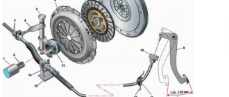
The design and principle of operation of a car clutch
A clutch is a transmission mechanism that transmits torque from the engine to the gearbox through friction. It also allows you to briefly disconnect the engine from the transmission and reconnect them smoothly. There are quite a few types of clutches. They differ in the number of driven disks (single disk, double disk or multi-disk), the type of operating environment (dry or wet) and the type of drive. Different types of clutches have their respective advantages and disadvantages, but the most common on modern cars is the single-plate dry clutch, either mechanically or hydraulically driven.
Driven disks
They are made from a base based on high-strength steel in the form of rings. On its two sides there are linings installed, which are fastened with strong rivets. For the required fit of the parts, radial-type slots are organized, which at the end end with the largest diametrical size.
But more often it is not a rigid driven disk that is used in the clutch of a tractor device, but one that has tangential or axial compliance. This makes it possible to create smoothness during switching on and simplifies the control of the machine.
Clutch: purpose, types, malfunctions, photos, videos.
The word coupling comes to us from German and Dutch. In German it is Muffe, and in Dutch it is mouwtje. In the Russian language, as well as in those from which it was borrowed, the word is used in several meanings. In the area of interest to us, a coupling is understood as a special drive in machines and mechanisms that transmits rotational motion (torque) from one shaft to another, coaxially located with the first.
PURPOSE
CLUTCH
The clutch in a car is designed to provide the ability to switch driving modes on the move and move away smoothly. With the help of a clutch, a short-term separation of the engine and transmission of the car is carried out, that is, the close contact of the driving and driven disks of the clutch mechanism is stopped.
Thus, the clutch is a part of a common mechanism, a single clutch unit. Often these two words are used as synonyms, for example: “squeeze the clutch” or “squeeze the clutch.”
In addition to cars and tractors of various types, couplings are installed on walk-behind tractors, chainsaws, stationary machines with variable modes of rotation of the main shaft.
TYPES OF CLUTCH
The design of the clutch is not the same type, and on each car model this unit has certain differences. However, certain similarities can be identified in the design of passenger car couplings. The constant elements of each of them are:
- flywheel;
- crankcase;
- central casing bolt;
- disks;
- box input shaft;
- fork with central compression spring.
According to the current classification, they are all divided into single- and multi-disc, and the latter are used relatively rarely for vehicles. The clutch drive may also differ:
- mechanical;
- hydraulic;
- combined.
Separately, we can mention electromagnetic couplings, which can be found on diesel locomotives and on certain machines - these are not relevant for a car. Operating conditions can also be distinguished – dry and wet couplings. For a tool equipped with an internal combustion engine, a centrifugal clutch can also be used, which automatically connects and disconnects the shafts, reaching the shaft speed specified by the design.
COMMON CLUTCH FAULTS
Despite the rather complex design of the vehicle coupling, if used correctly, there are practically no problems with it. There are only two common problems with the clutch: slipping of the clutch and the inability to disconnect it completely.
CLUTCH SLIPPING
The most common reason for this “behavior” of the clutch is the presence of oil contaminants on the friction linings. They may appear there after repair work or simple carelessness of the driver. This problem can be easily resolved - the flywheel and pressure plate are thoroughly cleaned of oil, after which the problem of clutch slipping no longer bothers the car owner.
The clutch may slip for another reason - wear of the linings themselves and the appearance of scoring on them. As a result, releasing the pedal does not bring the discs into full contact. To correct this problem, you need to adjust the free play of the pedal, and if this does not help, you will have to replace the friction linings with new ones - there is no other repair method.
THE COUPLING DOES NOT DISCONNECT COMPLETELY
There are also two reasons for this behavior of the coupling.
- Insufficient clutch pedal travel. This is often caused by poor clutch settings that allow too much free play. The problem is resolved by reconfiguring, which should be entrusted to a mechanic or an experienced driver.
- The levers that are equipped with each clutch have changed their original shape and can no longer be adjusted. They are subject to replacement. Sometimes, when a clutch operates with bent levers, the disc itself becomes warped, which leads to damage to the friction linings. In this case, they are also subject to unconditional replacement.
IS IT POSSIBLE TO EXTEND THE SERVICE LIFE OF THE CLUTCH?
Since the clutch is not one of the parts that is easy to buy and simply replace, most car owners quite reasonably think about the possibility of increasing its service life. There are no special tricks or ways to extend the life of this automotive unit; it is enough to follow simple and well-known recommendations:
- engaging/disengaging the clutch should be carried out as carefully and smoothly as possible, avoiding delays in the pedal in an intermediate position or sudden removal of the foot from the pedal when starting to move;
- It is not recommended to keep the clutch disengaged for a long time and then move away suddenly;
- carry out maintenance in a timely manner; however, if the driver lacks experience, this procedure should be entrusted to professionals.
Thus, the banal lubrication process must be carried out in strict accordance with the lubrication table recommended by the manufacturer. Excessive amounts of lubricant often lead to it getting on the disc linings and causing it to slip. When self-lubricating using a syringe, you should not do more than eight injections. Naturally, you should use only those lubricants that are recommended by the manufacturer of a particular vehicle.
Multi-plate clutch
Multi-disc clutch, due to the introduction of new technologies, is increasingly used in both cars and trucks with various gearboxes (manual, automatic, robotic). In addition, such clutches are used in transmissions of all-wheel drive vehicles to distribute the load between the front and rear wheels (axles). Multi-plate clutches can be dry or wet. Wet - using an oil bath, dry - without oil. The presence of oil ensures a smoother connection of the discs, improves the removal of heat and abrasive substances, and the movement of the discs along the splines during movement.
A significant disadvantage is the low coefficient of friction between the discs. An increase in the coefficient of friction is achieved by increasing the number of drive and driven disks, increasing the force of the pressure spring, and using new friction materials. Multi-plate clutches include: - driven discs (3 or more), made of thin steel, on which a layer of friction substance is applied (can be made of high-strength friction plastic).
Tractor clutch friction parts
The pads are designed to prevent wear and therefore can withstand severe thermal and dynamic loads. They are made on the basis of polymers or powdery compounds.
In the first case, they are a composition of many components. They consist of a base, reinforcement and filler. Substances such as rubber and resins, as well as their numerous combinations, are used as a base. Fillers are divided into metallic and non-metallic types.
The dimensions of the linings in the tractor clutch device are standardized and correspond to GOST 1786. They are made in the form of rings or truncated sectors.
Drive discs
They allow for the correct distribution of heat flows, as they are responsible for the action of all subsequent structural elements. That is, they are responsible for dispersion and absorption. To ensure the required values, materials are used in the form of gray cast iron of different grades: 18, 21, 22 and 24. They have a high degree of wear resistance and reduce wear on the linings used in the system.
The circle of the driven disks for performing work in conjunction with other parts has many projections, pins, spikes, teeth, veneer joints and tangential springs. All elements are evenly distributed over the surface of the products.