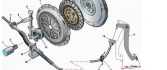
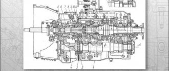
The clutch of the YaMZ-238 model is double-disc, dry, friction type, with a peripheral arrangement of cylindrical springs
The clutch housing 16 (Fig. 1), stamped from sheet steel, with the pressure disk 19 assembly is installed on the engine flywheel 20, and the driven disks 21 are installed on the splined part of the gearbox input shaft.
The front and rear driven discs are installed in a specific position, as shown in the figure.
The driven clutch discs are clamped by a constant force of cylindrical pressure springs 17 between the engine flywheel, the middle and pressure discs.
Thermal insulating gaskets 18 are placed under the springs on the pressure plate side. The pressure and middle drive disks are connected to the flywheel by four tires located on the outer surface of the disks.
When clamped, the driven disks transmit engine torque to the transmission input shaft.
The clutch is released using clutch 11.
The clutch with the bearing, moving towards the engine, moves the pressure disk away from the driven disk, transmitting force through four rigid pull-out levers 5. The working stroke of the clutch release clutch, taking into account free play, must be at least 18.2 mm (size “D”) .
The amount of free play is regulated by the clutch release mechanism. The thrust ring of the pull-out levers moves towards the gearbox by 27 mm due to the permissible wear of the friction linings.
Guaranteed clearances between the driven disks and the friction surfaces of the flywheel, middle drive and pressure disks when the clutch is disengaged as the linings wear are ensured by a mechanism for automatically adjusting the withdrawal of the middle disk, which consists of rods 1 fixed in each of the four spikes of the middle drive disk, split rings 2, to move along the rod which requires a certain force, thrust bars 4, which are bolted to the flywheel with the clutch casing, and disc springs 3 installed on the rod between ring 2 and bar 4.
When the clutch is released, the pressure plate 19 moves back at least 2 mm and releases the rear driven disk 21.
The middle drive disk 22, under the action of the spring 23, also moves back, until the ring 2 stops in the bar 4 through a disc spring, by an amount of 1.2+0.1 mm, freeing the front driven disk.
As the clutch friction linings wear out, the middle drive disk, under the action of the pressure springs of the pressure disk, moves to the flywheel, the rings 2 rest against the clutch housing, moving along the rods 1 and maintaining the size between the rings and the disc springs.
When the driven disc linings wear out, the end of the clutch release clutch will rest against the end of the gearbox input shaft bearing cover; in this case, replace the worn linings of the driven discs with new ones.
Design and principles of operation
The design of the coupling mechanism includes such elements as:
- flywheel;
- hydraulic power steering;
- overlays;
- a spring device that presses the disk against the flywheel housing;
- clutch release fork, clutch release drive;
- push-type coupling;
- coupling pedal shaft;
- pressure disk;
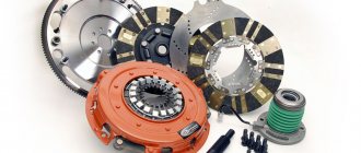
- double-disc or single-disc petal device;
- release bearing;
- protective casing;
- transmission drive shaft.
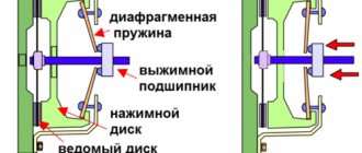
Principle of operation:
- When the driver presses the pedal, the shaft begins to rotate.
- A gap forms between the fork and the push-type coupling.
- The clutch, together with the bearing, begins to move, causing the bearing to exert pressure on the inner ring of the handle.
- The handle moves the pressure plate away from the driven disc.
- The spring mechanism is compressed, causing the disk to move towards the flywheel of the power unit.
- The splines of the driven disk move to the splines of the gearbox input shaft.
Installation on the clutch motor
- Using a special mandrel, the driven disk is installed on the flywheel. The friction lining on the spring plate is located towards the pressure disk, the elongated hub part is located outward from the motor.
- The pressure disk with the casing is mounted as an assembly, ensuring the coaxial position of the flywheel holes and the fastening of the clutch casing.
- We tighten the clutch bolts by hand to a depth of at least four millimeters.
- The bolt tightening torque limits are 60-70 Nm. It is necessary to tighten it gradually, evenly, without allowing the spring to distort.
- The ring must be centered relative to the axis of the crankshaft using a special mandrel.
How the repair is carried out
Main malfunctions and ways to eliminate them:
- The clutch mechanism is slipping. This may be due to the lack of free play of the pedal, jamming of the piston part, wear of the friction linings. In this case, it is recommended to adjust the free play of the pedal, clean all cylindrical elements and valves with kerosene, and replace damaged linings and cylinders.
- The clutch moves or does not disengage completely. Such a malfunction can be caused by an incorrectly adjusted length of the cylinder rod, insufficient air pressure in the pneumatic system, a leak in the piston seal, or failure of the pull-out levers. The rod length should be re-adjusted, the pneumatic system should be inspected and, if necessary, leaks should be eliminated, the cylinders should be flushed, and all damaged and worn parts should be replaced.
- The pedal does not return to its original position. It is recommended to adjust the gap between the back cover and the lock ring, replace worn valves, move the spring mechanism holder closer to the rod, eliminate defects in the rods, clean and lubricate the cylindrical elements of the system.
Features of gearbox installation
- Turn the ring on the coupling so that the protrusions do not coincide with the grooves of the bearing sleeve (position “a”).
- Unscrew the coupling until it stops.
- Install the gearbox and secure it with bolts.
- Move the clutch release clutch towards the thrust ring until it stops.
- Turning the clutch release fork shaft clockwise, move the clutch away from the engine (position “b”).
- Make sure that the coupling engages with the thrust ring. To do this, you need to apply additional force in the direction from the motor.
- The gearbox is finally secured.
Return to list of articles>>>
How to replace
Replacing the clutch is carried out in several stages:
- dismantling;
- parsing;
- assembly;
- installation.
How to remove
In order to dismantle the coupling mechanism, you must perform the following steps:
- Place the vehicle on a special platform or inspection hole.
- Remove the battery.
- Remove the air filter element.
- Remove the engine splash guards, which are located in the lower and side parts of the power unit compartment.
- Remove the front suspension cross member.
- Remove the front drive wheels.
- Drain the oil fluid.
- Disconnect the speed sensor using a screwdriver.
- Remove the reverse switch.
- Remove the engine harness holder.
- Unscrew the mounting bolts and remove the starter housing.
- Disconnect the engine mounts from the gearbox bracket.
- Move the clutch back.
- Remove the input shaft of the mechanism.
- Unscrew the mounting bolts from the coupling mechanism housing. The bolts are unscrewed one by one, in 2-3 steps.
- Remove the pressure plate along with the casing.
Assembly
Clutch mechanism assembly steps:
- Assemble the driven disk. To do this, it is necessary to attach friction linings to a plastic spring device.
- Assemble the pressure plate. You need to lubricate the rollers with a special liquid, place them in the hole of the pull handles, insert the lever into the groove that is located on the pressure-type disk, and install the finger. Attach the support forks to the levers and secure them with cotter pins.
- Assemble the pressure disk with the casing. This must be done under a press that can compress the springs and screw the bolts into the support forks. A driven type disk is placed under the press, and a pressure disk is placed on top. Heat-insulating washers and the spring mechanisms themselves are installed on special protrusions. Press the casing using a press and tighten the mounting bolts.
- Installing discs into the clutch housing.
Procedure for installing the clutch:
- Install the driven disc so that the extended end of the hub faces the flywheel.
- Install the drive disk element with rods.
- Install a second driven disk with the elongated end of the hub pointing towards the gearbox.
- Install the pressure plate.
- Attach the cut adjusting rings to the structure.
- Install the stop bars and secure them with the casing.
- Install the clutch mechanism on the flywheel, check the gap between the thrust rings and washers by engaging the clutch mechanism.
How to install disks
Many drivers are interested in how the clutch disc is installed on a MAZ.
In order to install clutch discs, you must:
- Disconnect the driveshaft.
- Remove the brake drum and pads from the wheels.
- Using a wrench, unscrew the fasteners from the axle shafts and pull them out.
- Unscrew the screws that adjust the position of the propeller shaft flange and gearbox.
- Disconnect the contacts of the sensor wires, which is responsible for turning on the reverse lights.
- Using a 12mm wrench, unscrew the mounting screws from the clutch mechanism protective cover.
- Remove the casing.
- Using a small crowbar, pry the gearbox housing away from the power unit.
- Remove the basket from the flywheel.
- Secure the flywheel.
- Remove damaged disk elements and replace them with new ones. The driven clutch disc should be directed towards the gearbox, and the pressure disc should be placed so that the hub is directed towards the engine.
- Reassemble the coupling mechanism by performing all steps in reverse order.
Removing the clutch
The clutch is removed from the engine along with the gearbox. This is done in the following order:
- The nut securing the lubricant hose is unscrewed.
- A lubricant hose is pushed into the cavity of the clutch housing.
- The gearbox is removed. The clutch release clutch should remain on the thrust ring of the diaphragm spring.
- The semicircular groove of the release clutch is aligned with the protruding lug of the safety ring. It needs to be sunk with something and held there through the central hole of the coupling.
- The lock ring is rotated relative to the bushing so that the grooves of the bushing and the protrusions of the ring coincide.
- The clutch is pushed towards the flywheel until it stops. The spring ring should come out of the groove of the shaped thrust ring and take its place in the rectangular one. This will be position "d".
- The coupling is disconnected. To do this, it must be moved in the opposite direction from the flywheel. The spring ring remains in the rectangular groove (position “e”) and is then removed from it.
- The pressure disk with the casing is removed. To do this, the clutch mounting bolts are gradually unscrewed in several steps. Severe distortions of the spring are not allowed. Defects of parts are carried out with the clutch disassembled. Find out what parts will be needed.
Service
Maintenance of this mechanism is carried out as follows:
- Carry out an external inspection of the pedal and, if necessary, adjust its free play.
- Bleed the hydraulic drive.
- Carry out diagnostics of the crankcase fastening elements and, if necessary, tighten the nuts.
- Carry out an external inspection of the tension spring device, lubricate the bearings and hydraulic coupling.
- Check the functionality of the clutch switch and the shaft sleeve.
- Inspect the fork and clutch pedal for wear and damage.
- Check the operation of the mechanism by changing the gears of the vehicle on the spot and during acceleration.
- Eliminate incorrectly set gaps between support rings and washers.
- Eliminate leaks in the system and lubricate all cylindrical elements with a special liquid.
- Check the gap between the rods and the piston part of the main cylindrical device.
How to make adjustments
Actions when adjusting the MAZ clutch:
- Adjust pedal free play. To do this, you need to put your foot on the pedal and squeeze the gas all the way. If necessary, reduce or increase the stroke of this device.
- Release the pedal and measure the distance to the lower mark of the coupling mechanism.
- The maximum stroke amplitude should not exceed 16 cm.
- Tighten all fasteners.
- Measure the pedal free play.
After the driver has adjusted the clutch mechanism, it is necessary to adjust the MAZ clutch basket:
- Place the transport on a special platform.
- Unscrew the mounting bolts that connect the gearbox and the car body.
- Remove the gearbox.
- Unscrew the screws of the push-type disk and remove it.
- Inspect the basket and replace damaged or worn parts.
- Adjust the position of the paws.
- Using the adjustment handle, set the paws to the positions shown in the MAZ repair manual.
- Tighten all mounting screws until they are secure.
- Reassemble the mechanism by repeating all steps in reverse order.
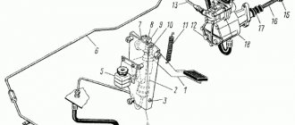
How to bleed the clutch on a MAZ
Bleeding the clutch is necessary when gears shift poorly or air gets into the hydraulic system.
Before starting the procedure, it is recommended to fill the hydraulic drive tank with working fluid to the 1-1.5 cm mark. Remove all dirt from the exhaust cylinder valves, remove the protective casing, remove the cap from the top of the master cylinder and put a special hose on it for bleeding.
Gradually it is necessary to lower the free end of the hose into the working fluid poured into the hydraulic drive, lightly pressing the pedal of the coupling mechanism. There should be an interval of 1-2 seconds between presses. A total of 4 pressures are required.
When pressed for the first time, the pedal must be immersed in liquid, at which time it is necessary to unscrew the valve half a turn. During 2, 3 and 4, all system mechanisms are pumped. When the bubbles disappear, you need to stop pressing the pedal. If during the procedure the level of working fluid decreases by 2/3, it is necessary to replenish the missing volume.
Not available:
| № | Part code | Name | Quantity per model, pcs. | |
| 3 | 338062 | Key 22x9.5 segment | 2 | Not available |
| 8 | 258038-P29 | Cotter pin 3.2x16 | 4 | Not available |
| 9 | 339640-P29 | Finger | 3 | Not available |
| 13 | 200265-P29 | Bolt M8-6gх40 | 1 | Not available |
| 14 | 5557Я-3504026 | Brake pedal shaft lever | 1 | Not available |
| 16 | 4320Ya3-1602060 | Clutch pedal shaft lever | 1 | Not available |
| 18 | 4320-3504010-01 | Brake pedal | 1 | Not available |
| 19 | 4320-1602070-02 | Buffer | 2 | Not available |
| 21 | 4320-1602091 | Adjustment tip | 2 | Not available |
| 23 | 5557Я-3504058 | Brake valve control lever assembly | 1 | Not available |
| 24 | 264020-P29 | Oiler 1.3 | 1 | Not available |
| 25 | 293508-P29 | Washer | 2 | Not available |
| 26 | 258056-P29 | Cotter pin 4x40 | 2 | Not available |
| 28 | 4320-3504065 | Rod assembly | 1 | Not available |
| 32 | 260087-P52 | Finger 12x35 | 4 | Not available |
| 33 | 258052-P29 | Cotter pin 4x20 | 5 | Not available |
| 34 | 4320Ya3-1602032 | Clutch release shaft | 1 | Not available |
| 37 | 4320Я3-1602027 | bracket | 1 | Not available |
| 38 | 250640-P29 | Nut M20x1.5-6N | 1 | Not available |
| 39 | 4320Я5-1602185 | A tube | 1 | Not available |
| 42 | 200263-P29 | Bolt M8-6gх35 | 4 | Not available |
| 43 | 250514-P29 | Nut M12-6N | 1 | Not available |
| 44 | 4320Я3-1602180 | Fork | 1 | Not available |
| 46 | 200319-P29 | Bolt M10-6gх50 | 1 | Not available |
| 49 | 8512 | Hydraulic fitting 8-M14x1.5-S | 2 | Not available |
| 50 | 337779-P29 | Union | 1 | Not available |
| 51 | 339098-P29 | Hose clamp | 2 | Not available |
| 54 | 252016-P29 | Washer 14 | 2 | Not available |
| 55 | 6363-1602170 | Hose | 1 | Not available |
| 56 | 00-10-00 | Worm clamp (12-22) | 2 | Not available |
see also
Comments 21
I saw a photo in the feed and thought that it was all about the New Year theme...
And for a release disk, for example, like this autosensey.ua/part-luk-124016310/, does it make sense to build something similar? Is it purely for fixation, or will it dent?
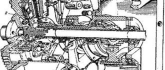
This is a device for disassembling and assembling the MAZ clutch basket. The basket is disassembled to replace the pressure pads or springs. On modern passenger cars, as far as I know, the diaphragm clutch cannot be repaired, it can only be replaced. On UAZs, Moskvichs and Volgas, the clutch is structurally similar to a truck clutch; such a device can be made there, correspondingly smaller in size.
Got it, thanks for the explanation
A friend of mine was struggling with this. Then he installed the old model, but he couldn’t install his own even for cheap.
Let's refresh our technical knowledge on this tricky coupling Here is all the information on this coupling Instructions: www.velikanrostov.ru/manu...o%20remont%20lepestok.pdf 2)
3) 4) 5) www.drive2.ru/l/7170502/
This design is already dying out, tell us about the petal type, the possibilities of repair. And here, too, people would be interested in possible defects and methods for eliminating them.
I'm not a mechanic, I'm a driver and I'm describing some of my tools for my car. As for the single-disc clutch, people, if possible, refuse it and install two-disc ones. There are constant problems with the release bearing. It often slips out of gear. I have to remove the box.
This design is already dying out, tell us about the petal type, the possibilities of repair. And here, too, people would be interested in possible defects and methods for eliminating them.
Let's refresh our technical knowledge on this tricky coupling Here is all the information on this coupling Instructions: www.velikanrostov.ru/manu...o%20remont%20lepestok.pdf 2)
3) 4) 5) www.drive2.ru/l/7170502/
Re-equipment of the T-150 tractor to install the YaMZ-236M2 engine
Technological process of installing the YaMZ-236 M2 engine on the T-150 tractor
Dismantling the SMD-62 engine and modifying the tractor frame
- Drain fuel, oil and coolant from engine systems.
- Clean the tractor from dirt and wash it.
- Remove the hood, sidewalls and trim panels, front protective grille and radiator casing, radiator muffler and air cleaner from the tractor for further use after installing the YaMZ engine.
- Disconnect fuel and coolant supply hoses, air lines, control rods, etc. from the engine.
- Loosen the engine mount to the clutch housing and to the tractor frame.
- Remove the SMD-62 engine from the tractor chassis, protecting the input shaft and the power take-off shaft in the gearbox from damage.
- Remove the two pins (7.37233) from the clutch housing.
- Remove ferrado discs from the engine for the purpose of their further use on the YaMZ engine.
- Remove the power take-off shaft from the tractor gearbox and release the fastening, the input shaft cover assembled with the stop and the release bearing housing.
- On the top flange of the right side member of the tractor front frame, make a 30x700 cutout for the ST-25 starter (an additional support angle is cut off for the ST-142 starter). Clean the cutout area.
Operating principles
The essence of the functioning of the transmission element is as follows:
- the pressure springs are pushed with one part into the assembly case, and the second into the pressure plate. All this is done with the help of heat-insulating washers;
- the pressure plate sends the action to the driven plates. In this case, these disks are shifted towards the case.
If the mechanism was at rest, then the cylindrical release springs fill all the required gaps that appear between all the spare parts of the assembly.
During operation of the device, the friction linings of the plates wear out. Their original parameters and properties deteriorate, which means timely replacement is necessary.
Leaf gas dynamic bearings
Gas-dynamic petal bearings are oil-free bearings that completely eliminate the use of oil in turbines and engines and increase the power density of aircraft turbines and engines, making them smaller, faster, hotter. As a result, they use less fuel to lift a larger load (passengers or heavier cargo).
Description:
Gas-dynamic petal bearings are oil-free bearings that completely eliminate the use of oil in turbines and engines and increase the power density of aircraft turbines and engines, making them smaller, faster, hotter. As a result, they use less fuel to lift a larger load (passengers or heavier cargo).
Gas-dynamic petal bearings completely relieve engines and turbines of the lubrication system, reduce engine weight and at the same time reduce the effort required for engine maintenance.
For reference. Airplane and helicopter turbo engines are currently lubricated with oil. But oil catastrophically loses its properties at high operating temperatures, at which turbines operate most efficiently. In addition, one rule of thumb suggests that up to a quarter of the turbine's weight consists of lubrication pumps, filters, and oil lines.
Leaf gas-dynamic bearings have a relatively simple design and operating principle. The bearing surface of the bearing is formed by thin elastic metal plates. A low-friction anti-friction coating is applied to the surface of the plates, which “lubricates” the bearing at start-up until the shaft can rotate fast enough to create a wedge of air between it and the bearing.
As the rotor speed increases, the gas layer completely separates the working surfaces of the rotor and bearing. An increase in speed is accompanied by an increase in the bearing's load-bearing capacity. Basically, the shaft floats on a film of air, similar to an air hockey puck. The only difference is that there is no need to pump air to the support itself.
The rotation of the shaft is provided by its own compressed air.
Gas dynamic petal bearings change shape depending on the conditions in which they operate to create optimal clearance geometry.
Leaf gas-dynamic bearings have unique stabilizing properties. They prevent the occurrence of vortex instability of the rotor and operate with limited imbalance.
Currently, two main types of gas-dynamic petal bearings are known: bearings with backing corrugated elements and one load-bearing petal (bump type) and bearings with mutually overlapping petals (leaf type). Bump type bearings have a greater load-bearing capacity, and leaf type bearings have a greater damping capacity, so the first type is used in stationary machines, and the second type is used in transport machines.
Advantages:
– autonomy of operation (no renewable lubrication and no need to supply air or other working gas under pressure into the working clearances of the bearing),
– effective damping of rotor vibrations due to the dissipation of vibrational energy in numerous friction zones inside the bearing,
– the ability to simplify the requirements for the accuracy of manufacturing parts and assembly due to the presence of sufficiently large clearances inside the bearing,
– reduced requirements for the purity of working air (or other gas),
– reduced requirements for rotor balancing accuracy,
– great resource. The predicted service life of turbomachines with gas-dynamic petal bearings is approaching 300 thousand hours,
– allows to significantly reduce the number of failures of high-speed turbomachines,
– high degree of environmental cleanliness (no oil),
– high reliability, heat resistance.
Application:
– engines,
– turbojet engines,
– turbomachines,
– electric cars,
– high-speed turbogenerators.
Site Map
release bearing on the UAZ petal basket hydrodynamic petal bearing replacing the MAZ release bearing single-disc petal petal clutch need release bearing clearance flap bearings gas petal bearing release bearing MAZ single-disc petal assembly of the release bearing on the Yamz petal basket installation of the MAZ release bearing single-disc lep Installation of release bearing MAZ single-disc petal 184 installation of the release bearing MAZ single-disc petal video