Clutch design and operation
The clutch is designed to temporarily separate the engine and transmission and smoothly connect them.
When engaged, the clutch transmits torque from the engine to the gearbox. Temporary separation of the engine and transmission is necessary when changing gears, braking and stopping the car, and a smooth connection is necessary after changing gears and when starting off. The car has a single-plate, dry clutch with a central diaphragm spring and a hydraulic drive. The clutch has one driven disk, and its driven and driven parts are pressed against each other by a central spring. The clutch transmits torque from the engine through dry friction forces.
The force from the pedal to the clutch release fork is transmitted through the fluid.
Rice. 26. Clutch:
1 — central pressure spring: 2 — driven disk; 3 — friction lining; 4 — disk; 5 - hub; 6 — torsional vibration damper; 7 — pressure disk; 8 — flywheel: 9 — clutch housing; 10 - bolt; 11 — gearbox input shaft; 12 — clutch release; 13 — clutch release fork; 14 — clutch release bearing; 15 — thrust flange of the pressure spring; 16 — clutch casing; 17 — adjusting nut; 18 — clutch slave cylinder; 19 — fork spring; 20 - support ring; 21 - latch.
The clutch (Fig. 26) includes: driving parts (flywheel 8, casing 16, pressure plate 7), driven parts (driven disc 2) and on and off parts (spring 1, clutch 12, bearing 14). The casing 16, the pressure disk 7 and the pressure spring 1 are a non-separable unit, which is attached to the flywheel 8 with bolts 10. Between the flywheel and the pressure disk on the splines of the drive shaft 11 of the gearbox there is a driven disk 2, consisting of a hub 5, a steel split disk 4 and friction linings 3. The driven disk is equipped with a spring-friction torsional vibration damper 6, which provides an elastic connection between the hub 5 and disk 4, as well as damping of torsional vibrations. The diaphragm spring 1, in the free state, has the shape of a truncated cone with radial slots extending from its inner edge. Radial slots form eighteen petals, which are elastic release levers. The elasticity of the levers helps ensure smooth clutch operation. Spring 1 is secured to the clutch housing 16 using rivets and two support rings 20. In this case, its outer edge, in contact with the pressure disk 7, transmits the force from the spring to the pressure disk.
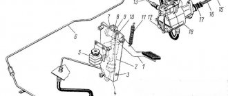
Rice. 27. Clutch drive:
a — pedal and master cylinder; b - working cylinder and fork: 1 - servo spring; 2 — pedal spring; 3 — pedal travel limiter; 4 - pedal; 5, 14 — pushers; 6, 18 — cylinder bodies; 7 — pusher piston; 8, 19 — cylinder pistons; 9, 20 — piston springs; 10, 21 — fittings; 11 — clutch release bearing; 12 — ball joint; 13 — clutch release fork; 15 - lock nut; 16 — fork spring; 17 — adjusting nut.
The hydraulic clutch drive (Fig. 27) includes: pedal 4, master cylinder and its reservoir, working cylinder, connecting pipelines and clutch release fork 13. When the clutch is disengaged, the force from pedal 4 through pusher 5 of the master cylinder is transmitted to pistons 7 and 8, which displace fluid into the pipeline and the working cylinder. The piston 19 of the working cylinder through the rod 14 turns the clutch release fork 13, which moves the clutch with bearing 11. The bearing through the thrust flange 15 (see Fig. 26) moves the inner edge of the spring 1 towards the flywheel 8. The spring bends in the opposite direction, its outer the edge through the clamps 21 removes the pressure plate 7 from the driven disk 2, and the clutch disengages - it does not transmit torque from the engine to the transmission. When the clutch pedal is released under the action of spring 1, the pressure plate presses the driven disk against the flywheel, and the clutch engages and transmits torque to the transmission. In this case, all other parts of the clutch and its drive return to their original position under the action of springs: the release fork, the pistons of the main and working cylinders and the clutch pedal.
Cabins of SKD-5, SK-5 AND SK-6 combines
Purpose and work. To consolidate knowledge of the use of combine harvester controls and instruments. Consider the features in the arrangement of instruments and controls on various models of combines. Check and adjust the control mechanisms of the working bodies of combine harvesters. Study the structure of the automatic threshing load regulator (ARZM) and the driver’s seat.
Workplace equipment. Spring dynamometer for 5 kgf (49.03 N), ruler 0-300 mm, caliper ShTs-P-0.1-200, probe (set), indicator ICH 05 class. 1, a set of feeler gauges for checking gaps in the threshing apparatus, an ignition key for the SKD-5 instrument panel, a 500 g bench hammer, an A175x0.7 screwdriver, a jack, a stand for the combine. Wrenches 8X10; 12X14; 17X19; 22X24; 27X30; 32X36; 36X41; wrench for round nuts 46-52 mm.
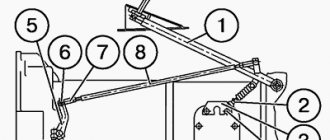
Sequence of work execution. Inspect the cabins of the combines and pay attention to the fact that all combines have the same arrangement of all pedals and gear shift lever. Note that on the SK-5 and SK-6 combines, levers 1 (Fig. 100, 101) for regulating the fuel supply, lever 16 (see Fig. 100) and lever 7 (see Fig. 101) for turning on the drive of the combine mechanisms are located similarly. , handle 23 (see Fig. 100) and handle 13 (see Fig. 101) for releasing the parking brake.
Pay attention also to the fact that on the SK-6 combine, the lever 14 for turning on the unloading auger, the handle 17 for regulating the speed of the first drum and the lever 16 for adjusting the gaps in the threshing apparatus are located to the left of the driver. On the SKD-5 and SK-5 combines, these levers are located to the right of the combiner. Please note that there are two instrument panels installed in the cabin of the SK-6 combine. On the left panel 15 (see Fig. 101) all the signal lights and alarm switches are installed, on the right panel 5 there are instruments that control the operation of the engine and the tachometer of the second drum.
On SK-5 and SKD-5 combines, all instruments are concentrated on one panel (Fig. 102, 103). The inscriptions explain the purpose of each of the switches and devices.
Find on the SK-5 and SK-6 combines equipped with automatic thresher loading regulators, the main components and controls for this regulator.
Inspect the ARZM mechanisms on both combines and make sure that they are basically the same.
Using Fig. 104, find on the SK-5 and SK-6 combines the grain loss indicator units (abbreviated as UPZ): loss converters 1 and 6, measuring unit 2 and loss indicator device 5.
Find cabin heaters on combines and consider how heat is removed from the engines. Consider fans for blowing the driver and for centrifugal air purification.
Check the availability of tools and accessories and begin work.
Clutch - device
The illustrations show the clutch design before 2009 and after. Since 2009, Lada 21214M cars have been equipped with a clutch drive with automatic compensation for wear of the driven disc friction linings.
Clutch and its hydraulic drive
(until 2009)
1 – clutch release fork pusher; 2 – adjusting nut; 3 – lock nut; 4 – working cylinder of the hydraulic clutch release; 5 – fork release spring; 6 – fitting for bleeding; 7 – flexible hose for hydraulic clutch; 8 – central pressure diaphragm spring; 9 – pressure disk; 10 – flywheel; 11 – damper spring; 12 – driven disk; 13 – pipeline;
14 – hydraulic drive reservoir; 15 – clutch housing; 16 – gearbox input shaft; 17 – clutch release bearing clutch; 18 – clutch release bearing; 19 – ball support for the clutch release fork; 20 – clutch release fork; 21 – master cylinder of the clutch release drive; 22 – clutch pedal; 23 – clutch pedal release spring; 24 – brake pedal; 25 – servo spring; 26 – pedal axis.
Clutch device (after 2009)
Slave cylinder and clutch release fork of a car since 2009: 1 - clutch release bearing; 2 — ball joint; 3 — clutch release fork; 4 — clutch release fork cover; 5 — bracket fastening bolt; 6 — bracket for fastening the working cylinder; 7 — working cylinder body; 8 — air release valve
The clutch is single-plate, dry, with a central diaphragm-type pressure spring. It is located in an aluminum crankcase, bolted to the engine block and structurally integrated with the gearbox. The clutch drive is hydraulic.
The clutch housing is connected to the flywheel with six bolts. The flywheel has three pins, which, when installed, fit into the corresponding holes in the casing, centering it. The casing is connected to the pressure plate by three pairs of elastic steel plates with rivets. The other three plates connect the casing to a thrust flange facing the clutch release bearing (“release”). This assembly (“clutch basket”) is balanced on a stand, so it should be replaced as a whole. Replacement is necessary if the surface of the pressure plate is severely worn or the spring is “settled.”
The driven disk assembly with a spring torsional vibration damper is installed between the flywheel and the clutch housing and can move along the splines of the gearbox input shaft. The disk is replaced if there is more than 0.5 mm of runout in the area of the linings, their cracking, scuffing or uneven wear, as well as if the distance from the surface of the lining to the rivets is less than 0.2 mm.
Checking the operation of combine control mechanisms
Check and adjust the steering:
- Raise the rear wheels of the combine with a jack and install a stand.
- Rotate the steering wheel to set the rear wheels of the combine to the position corresponding to straight movement. Determine its free play by rotating the steering wheel. If the stroke value exceeds 40 mm along the length of the steering wheel arc, then it is necessary to eliminate excess gaps in the connections: bipod 4 with shaft splines 5, ball pin 8 with plug nuts 9, worm 13 with roller 2.
The force on the steering wheel should be no more than 3 kgf (29.41 N). After rotating the steering wheel to the right or left all the way and then in the opposite direction by 1.5 turns, the bipod 4 should become vertical, and the wheels should have the same direction as when moving in a straight line.
Check and adjust the brake system of the combine (for all combines, the brake pedals of the left 30 and right 32 wheels are located to the right of the steering column):
- Check the brake fluid level in the reservoirs of the main hydraulic cylinders 36: unscrew the reservoir cap; Depress pedal 30 by hand until resistance to movement appears. The pedal should not go down more than 2/3 of its full travel. If the pedal “falls”, this indicates the presence of air in the brake system.
- Bleed air from the brake system.
- Lower the pedal until resistance begins to move and check the fluid level in the reservoir. The normal level is 10-15 mm below the top edge of the tank.
- Keeping the pedal in the down position, add fluid to the reservoir to the normal level and screw on the cap.
- Measure the free play of the brake pedal. Place a ruler at the end of the pedal and, holding it, lower the pedal until resistance to movement appears. Take readings from the ruler scale. The pedal free play is 25-35 mm. If the measured free play is close to the upper limit, then you need to adjust the brakes in the following sequence:
- Release the parking brake handle 27 (see Fig. 106).
- Raise the drive wheel axle with a jack and remove wheel 23.
- Open the brake drum hatch cover and, turning it, measure the gaps at the ends of the brake pads with a feeler gauge. If the gap is more or less than 0.2 mm, then you need to adjust it by rotating each of the four cap nuts with a pry bar.
- Close the drum window cover, put the wheel on and remove the jack.
- Adjust the length of the main hydraulic cylinder pusher. Loosen the pusher lock nut and, rotating it, move it until it contacts the piston, and then screw the pusher half a turn into the connecting fork and tighten the lock nut.
- Check the free play of the right and left brake pedals. If the stroke turns out to be different, you need to correct it by changing the length of one of the pushers.
For joint braking, the pedals can be locked with latch 31.
For all combine harvesters, the clutch pedal is located to the left of the steering column.
Check and adjust the clutch of the SKD-5 combine:
- Place a ruler at the end of the pedal and, pressing the pedal with your hand, lower it until resistance to movement begins. If the free play is more than 25 mm, then it is necessary to adjust the length of the control rods.
- Disconnect rod 17 from clutch pedal lever 15
- Loosen the locknut and unscrew bolt 9 2-3 turns. Pull the lever until the release bearing comes into contact with the release levers. Insert a 2 mm thick feeler gauge between the end of bolt 9 and lever 8 and screw in bolt 9 until it comes into contact with the feeler gauge. Tighten the locknut of bolt 9.
- Move lever 8 all the way to bolt 9. Loosen lock nut 18 of the fork and, rotating rod 17, adjust its length until the end of the rod coincides with the hole in lever 15. Connect rod 17 to lever 15.
READ How to bleed the clutch on a Ford Focus 1
Check and adjust the parking brake. On SK-5 and SK-6 combines, the parking brake handle is located to the left of the clutch pedal. The parking brake is designed to hold the combine when parked and on slopes up to 16°.
- Check the operation of the parking brake by pulling handle 27 up as far as it will go. If the handle is fixed higher than in the fourth slot from the bottom, then you need to shorten lever 38 or cable 37 (see Fig. 106).
- Release the brake by turning the handle around the axis and moving it down.
Check and adjust the gear shift mechanism. On all combines the gear shift lever is located under the steering column. The gear shift diagram is shown on the plate. By moving the lever to the left and forward, first gear is engaged, to the left and backward is reverse gear, to the right and backward is second gear, and to the right and forward is third gear.
- Lift the rubber cap from the rocker mechanism and check the installation of the rockers. In the central position, the grooves on both scenes should be located opposite each other.
- Loosen the fork locknuts 35 (see Fig. 106) and, rotating them, set the rocker arms to the correct position.
Check the operation of the fuel control lever. On the SK-5 and SK-6 combines, the fuel supply control lever is located in front of the steering column, and on the SKD-5 combine, such a lever is installed on the right side of the bunker wall. On all combines, to increase the fuel supply, the lever must be moved back, towards you, and to decrease it, it must be moved forward, away from you.
Check the operation of the concave clearance control lever. On the SK.-5 and SKD-5 combines, levers with sectors are installed to the right of the driver’s seat to change the gaps in the threshing apparatus. On the SK-6 combine, such a lever is installed on the left. On all combines, the lever must be moved down to increase clearance.
- Move levers 14 (see Fig. 100) and 16 (see Fig. 101) up the sector until it stops.
- Open the inspection hatches in the thresher panels and measure the gaps at the inlet and outlet. Make sure there is no saddle-to-slave misalignment.
- Rotate the drum manually to ensure that the whips do not touch the concave.
Check the operation of the hopper unloading auger clutch. On SKD-5 and SK-5 combines, the mechanism for turning on the unloading auger is located on the front wall of the bunker. On the SK-6 combine, the lever for turning on the bunker unloading auger is located in the left front corner of the cab under the instrument panel. By moving the lever back, the unloading auger drive on the SK-6 and SKD-5 combines is turned on.
- Move the unloading auger activation lever to the “on” position. In this position, the jaw clutch teeth should overlap to their full depth.
- Move the lever to the “off” position. The gap between the teeth of the engagement clutch must be at least 3 mm.
- Adjust the gap by changing the length of the adjusting rod.
Check the operation of the threshing clutch engagement lever and the header drive release lever (the location of these levers is the same on the SK-5 and SK-6 combines):
- Move levers 16 (see Fig. 100) and 8 (see Fig. 101) back to turn on the working parts of the header.
- Using a caliper, measure the distance from the limiter to the belt. It should be no more than 5 mm. The gap is adjusted by moving the stopper groove relative to the bolt when the fastening nut is released. On the SKD-5 and SK-5 combines, the threshing clutch is engaged by moving forward, away from you, and on the SK-6 combine, vice versa. To adjust the mechanism for engaging the threshing clutch on the SKD-5 and SK-5 combines: 1. Set the gear shift lever to the neutral position. Disconnect the drive clutch of the combine's working parts. Turn on the decompressor.
- Remove the clutch hatch cover. Rotate the clutch shaft and place equalizing lever 3 opposite the hatch in the clutch housing.
- Using a feeler gauge, check the gap between cap 2 and the end of special bolt 1 through the slot in cap 2.
- The gap value of 0.5 mm is set by loosening the lock nut and rotating bolt 4.
- Having removed the dipstick and holding equalizing bolt 4 with a wrench, tighten the nut and check the gap again. The gaps of the other two equalizing levers are adjusted in the same way.
Check the operation of the drum speed control handles, which are available only on SK-5 and SK-6 combines. On the SK-5 combine, such a handle 17 (see Fig. 100) is located to the right of the seat. To increase the speed of the drum, it is rotated counterclockwise.
On the SK-6 combine, this handle 17 (see Fig. 101) is installed to the left of the driver. By rotating the handle clockwise while the thresher is running, the speed of the drum increases.
Check the operation of the hay unloading mechanism. The pedal of the hay unloading mechanism on all combines is the outermost pedal on the right. Check the operation of the unloading mechanism by pressing the pedal. Both latches must open at the same time, otherwise you will have to adjust the length of the rods by screwing the forks onto the eye bolts.
Check the installation of the hydraulic system distributor handles. Depending on the configuration of the SK-5 and SK-6 combines, the number of distributor sections can vary from five to seven. The procedure for using the handles is explained by signs with conventional symbols. Move each of the handles from one extreme position to the other. The length of the adjusting rods must be such as to ensure full travel of the spools in both directions from the neutral position.
On the SKD-5 combine, the neutral position of the distributor handles of the travel speed variator and the distributor valve must ensure complete coincidence of the holes of the spools and the distributor bodies.
Check the operation of control devices and alarm systems:
- Turn on the ignition switch on the Sibiryak combine or the mass switch (on the SK-5 and SK-6 combines it is located on the side of the landing).
- Apply the hand parking brake. Red light 21 (see Fig. 102) and 10 (see Fig. 103) should light up.
- Move switch lever 10 (see Fig. 102) to the left. The green light 20 should blink (see Fig. 102).
- Set switches 2 (see Fig. 102) to the “sidelights, taillights and instruments are on” position. Move the switch to the “headlights on” position.
- Set the low and high beam headlights using the foot switch. When the high beam is on, blue lights 1 should light up (see Fig. 102).
- Turn on switches 5 (see Fig. 102) the rear lights.
- Turn on the lamp with switches 18 (see Fig. 102), the blower fan with switches 4 (see Fig. 102), and the air purification fans with switches 3 (ohm. Fig. 102).
- Turn on the lighting in the grain bin using switch 19 (see Fig. 102). Press the hopper full indicator valve. When the contacts are closed, the green light 9 will light up.
- Check the operation of the straw walker alarm by pressing the valve against the thresher cover. If the indicator is working properly, red light 8 will light up and an audible signal will sound. Turn switches 17 (see Fig. 102) to the “off” position.
- Press the pedal of the stacker unloading mechanism and manually open the rear stacker valve. Red light 16 should light up (see Fig. 102). Close the rear valve.
- Insert a wooden block between the scraper and the casing of a grain or grain elevator. When turning the augers of grain or grain elevators, cause the safety clutches to slip.
READ How to adjust the clutch on gas 53
The red light 8 on the instrument panel should light up and the sound signal should sound. Turn off the signal with switch 17 and remove the block.
adjustment :
- Adjust the tilt of the seat back with screws 7
- Loosen nuts 1 on both sides of the seat and move the seat along guides 2, adjusting the forward position of the seat.
- Adjust the seat height by rotating the threaded bushing 4.
- Adjust the seat according to the driver’s weight by rotating screw 3. Levers 5 and 6 of the parallelogram under load should be set to an almost horizontal position.
- Turn handle 9 up and tilt the seat back. If the seat rocks for a long time after a push or becomes too hard, then you need to install 3 special washers on the screw or disassemble and wash the shock absorber.
Remove and disassemble the seat shock absorber:
- Unscrew the two nuts securing the shock absorber rod to the upper seat bracket. Unscrew the nut of the lower bolt, unscrew the bolt and remove two rubber and one metal bushings. Remove the shock absorber from the seat.
- Secure the shock absorber vertically in a vice. Unscrew nut 17 and remove washer 27
- Unscrew round nut 26 and remove rod 28 from the shock absorber body along with guide 18, spring 19, races 23 and 25, seals 21, 22 and 24.
- Unscrew nut 8 of piston 13. Remove spring 9, plate 10, sleeve 11, plate 14, spring 15 and plate 16.
- Reassemble the shock absorber in reverse order. Measure the outer size of the bushing I. If it is less than 11.99 mm, replace the bushing, otherwise the seat will sway too much. Screw nut 8 all the way into plate 10 with a tightening torque of 5-7 kgf-m (49.03-68.64 N-m). The housing nut 26 is tightened with a tightening torque of 5-7 kgf-m (49.03-68.64 N-m).
Disassemble the ARZM distributor:
- Disconnect the distributor spool plug 9 from the lever, the distributor body from the pipelines and remove it from the mounting brackets 1 on the combine.
- Unscrew plug 20 of the overflow section, pull out spring 21 and piston 22.
- Unscrew plugs 23 of shut-off valves, pull out springs 24, balls 25 and press out valve seat 26.
- Unscrew nut 11, unscrew screw 10, bolts and remove cover 12 of the safety valve.
- Pull out bushing 16 with spring 15, guide 17 and ball 19. Remove O-rings 13, 14 and 18 from bushing 16 and screw 10.
- Unscrew nut 7, pull out spring 6 with washer 3. Disconnect hollow axle 5 from fork rod 9. Unscrew cup 4 from spool body.
- Unscrew the three clamping screws and disconnect the overflow section from the spool section and from the rear cover.
Inspect the rubber sealing rings installed at the joints of the three sections, check their integrity and reassemble the distributor in the reverse order.
Specifications
Dimensions:
- length – 7607 mm;
- width – 3930 mm;
- height – 4100 mm.
The mass of the combine is 7400 kg.
Performance characteristics:
- base header width – 5000 mm;
- productivity – 5 kg/sec;
- drum rotation speed – 2900 rpm;
- number of knife attachments – 64 pcs.;
- Hopper capacity – 3000 l;
- bunker unloading speed – 40 l/sec;
- unloading height – 2900 mm.
Modifications and features
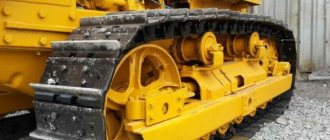
Niva SK 5 is one of the most common domestic grain harvesters. , in addition to the basic version, offered a huge number of modifications of this model. The most common versions:
- Niva SK 5A – basic variation with an increased power engine (120 hp);
- Niva SK 5AM - an improved modification with a 140 hp unit. and a transmission shifted to the left;
- Niva SK 5M-1 – version with hydrostatic transmission;
- Niva SKP 5M-1 is a model additionally equipped with a replaceable half-track. The improvement made it possible to use the combine on soil with high humidity;
- Niva SKK 5 is a steep-slope variation designed for use on surfaces with a slope of up to 30 degrees.
The basic Niva SK 5 has been modernized several times. The latest versions of the combine have acquired fluorine rubber seals with a long service life (previously rubber seals were used). Tight connections increased the reliability of the hydraulic system. The new generation Niva SK 5 used drive belts produced in Germany, which increased the operating time of the variator.
Series advantages:
- low cost. The model will cost much less than most analogues;
- efficiency;
- simplicity of design and ease of maintenance and repair;
- availability of spare parts, which are sold almost everywhere and are inexpensive;
- adaptability to Russian working conditions. Niva SK 5 feels great on specific soil and in harsh climates; the combine is not afraid of low-quality fuel.
Disadvantages of the series:
- the belt drive does not add smoothness on relatively soft soil with a full bunker;
- the attachment system for the reaping part is not particularly reliable;
- The build quality of the model is not always significant.
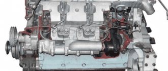
Engine
The basic versions of the Niva SK 5 were equipped with 5 diverse power plants:
- SMD-17K (power – 100 hp);
- SMD-18K (power – 100 hp);
- SMD-19K (power – 120 hp);
- SMD-20K (power – 120 hp);
- SMD-21K (power – 120 hp).
Later, a more powerful 140-horsepower unit appeared.
All of the above engines operated on diesel fuel and had a similar design (4-stroke units with an in-line design and 4 cylinders). The 120- and 140-horsepower variations were equipped with supercharging. Before entering the turbine, the air flow was forcibly cooled, which improved engine performance. Old modifications of the units had a gasoline start type, new versions were equipped with a starter with a long service life.
Modern Niva-Effect combines are equipped with a D-260 diesel engine (power - 155 hp), which operates reliably even under critical loads. In terms of fuel consumption, the unit looks much more economical than previous engines.