When buying bread in a store, people very often don’t even think about how hard and responsible work it is to grow this very bread. Centuries pass, and bread invariably occupies a dominant place in the diet. How many expressions, aphorisms and wisdom are associated with this product. And today we will talk about one of the tools that plays a vital role in bread production.
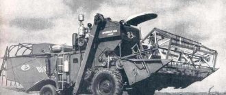
1. SK-3
Self-propelled harvester, 3rd model. Soviet grain harvesting machine, which was created by the GSKB for self-propelled grain combines and cotton harvesting machines in the city of Taganrog. The project was led by Canaan Ilyich Izakson. The car was produced from 1958 to 1964. In total, 169 thousand combines were created. This was the first Soviet combine harvester equipped with hydraulic power steering. SK-3 was also awarded a diploma from the Brussels exhibition.
2. SK-4
Self-propelled combine, 4th model. As you might guess, it replaced an older model - SK-3. The machine was produced from 1964 to 1974 at the Taganrog Combine Harvester Plant, as well as at Rostselmash. The grain harvester received an award from the Leipzig International Trade Fair, as well as awards from trade fairs in Brno and Budapest. The team developing the machine under the leadership of H.I. Izakson was awarded the Lenin Prize.
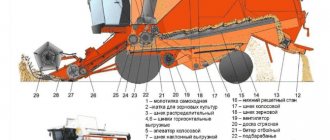
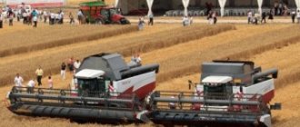
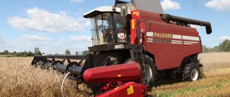
3. SKD-6 “Sibiryak”
A two-drum Soviet combine harvester, which was produced from 1981 to 1984 at the Krasnoyarsk Combine Harvester Plant. The car was a product of a deep modification of the SKD-5 “Sibiryak”, which was produced since 1969 and, despite its high reliability, became obsolete by the 80s of the 20th century. The machine had many “special” modifications, including for harvesting rice, working in areas without black soil, and a model with an extended track.
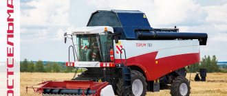
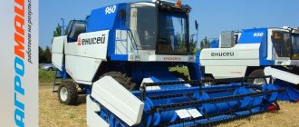
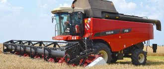
4. Yenisei 1200
Even young people should remember the combine harvester with the beautiful name “Yenisei” well from their childhood. The fact is that production of the car began in 1985. The combine was suitable for harvesting a wide variety of crops, including sunflowers, herbs, legumes and cereals. The machine could also harvest crops in “hard-to-reach” areas of the field.
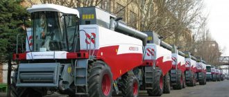
5. Don-1500
Perhaps the most popular combine harvester in the CIS after the collapse of the Soviet Union. The car began mass production in 1986. For objective reasons, the car was used for a very long time in the former republics of the union. The widespread abandonment of the combine harvester began only in 2006, when it was quickly replaced by more advanced imported and domestic models.
6. KSG-F-70
A very interesting example. A Soviet tracked combine harvester, which was developed specifically for working on waterlogged soils. For the most part, the machine worked with forage crops: grass and corn. The Donselmash combine was produced in the city of Birobidzhan. Most of these machines were in service with Far Eastern farms.
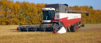
7. SK-5 "Niva"
Soviet combine harvester, produced since 1970 by the Rostselmash enterprise. The development was led by Izakson Canaan Ilyich. The machine is notable for the fact that it could become the hallmark of Soviet combine harvester construction. There is nothing surprising in this; the car was one of the most widely used in the USSR of all time.
Sibiryak combines have been produced by a plant located in Krasnoyarsk since 1969. The equipment is designed for harvesting cereals and legumes.
When installing additional equipment, it was used to collect sunflowers and cereals.
Creation
Despite the growth of the main indicator of reliability - the availability factor, the design of the SKD-5 Sibiryak combine, produced since 1969, by the end of the 70s was already obsolete and no longer met the requirements for grain harvesters. Work on the deep modernization of the old Sibiryak ended with the launch of the new SKD-6 into serial production in February 1981. The Nazarovo Agricultural Machinery Plant has mastered the production of harvesting parts with a working grip of 5 m for the Krasnoyarsk plant. The design of the SKD-6 increased throughput, productivity and reliability of the technological process, reduced the duration of combine maintenance, and special attention was paid to cabin comfort.
Purpose of the equipment
The combine is used mainly to harvest grains and cereal crops using direct, separate combining. Thanks to additional equipment, the functionality expands, allowing you to process other crops:
- Cereals.
- Legumes.
- Soy.
- Sunflower.
- Corn for grain and silage.
- Seeds of herbs.
Each part included in the Sibiryak Combine performs a specific job.
Sources
- “Tractors and agricultural machines”, No. 10, 1981.
- Chernoivanov V.I., Andreev V.P.
Restoration of parts of agricultural machines - M.: Kolos, 1983.
When buying bread in a store, people very often don’t even think about how hard and responsible work it is to grow this very bread. Centuries pass, and bread invariably occupies a dominant place in the diet. How many expressions, aphorisms and wisdom are associated with this product. And today we will talk about one of the tools that plays a vital role in bread production.
1. SK-3
Self-propelled harvester, 3rd model. Soviet grain harvesting machine, which was created by the GSKB for self-propelled grain combines and cotton harvesting machines in the city of Taganrog. The project was led by Canaan Ilyich Izakson. The car was produced from 1958 to 1964. In total, 169 thousand combines were created. This was the first Soviet combine harvester equipped with hydraulic power steering. SK-3 was also awarded a diploma from the Brussels exhibition.
2. SK-4
Self-propelled combine, 4th model. As you might guess, it replaced an older model - SK-3. The machine was produced from 1964 to 1974 at the Taganrog Combine Harvester Plant, as well as at Rostselmash. The grain harvester received an award from the Leipzig International Trade Fair, as well as awards from trade fairs in Brno and Budapest. The team developing the machine under the leadership of H.I. Izakson was awarded the Lenin Prize.
3. SKD-6 “Sibiryak”
A two-drum Soviet combine harvester, which was produced from 1981 to 1984 at the Krasnoyarsk Combine Harvester Plant. The car was a product of a deep modification of the SKD-5 “Sibiryak”, which was produced since 1969 and, despite its high reliability, became obsolete by the 80s of the 20th century. The machine had many “special” modifications, including for harvesting rice, working in areas without black soil, and a model with an extended track.
4. Yenisei 1200
Even young people should remember the combine harvester with the beautiful name “Yenisei” well from their childhood. The fact is that production of the car began in 1985. The combine was suitable for harvesting a wide variety of crops, including sunflowers, herbs, legumes and cereals. The machine could also harvest crops in “hard-to-reach” areas of the field.
5. Don-1500
Perhaps the most popular combine harvester in the CIS after the collapse of the Soviet Union. The car began mass production in 1986. For objective reasons, the car was used for a very long time in the former republics of the union. The widespread abandonment of the combine harvester began only in 2006, when it was quickly replaced by more advanced imported and domestic models.
6. KSG-F-70
A very interesting example. A Soviet tracked combine harvester, which was developed specifically for working on waterlogged soils. For the most part, the machine worked with forage crops: grass and corn. The Donselmash combine was produced in the city of Birobidzhan. Most of these machines were in service with Far Eastern farms.
7. SK-5 "Niva"
Soviet combine harvester, produced since 1970 by the Rostselmash enterprise. The development was led by Izakson Canaan Ilyich. The machine is notable for the fact that it could become the hallmark of Soviet combine harvester construction. There is nothing surprising in this; the car was one of the most widely used in the USSR of all time.
The base of the previous generation combine was used to create the 6 series equipment. The main power plant is the SMD-20 engine. SKD 6 Siberian is suitable for harvesting unevenly ripened, difficult-to-thresh crops.
The previous SKD5 series showed good results and guaranteed a high level of performance. But the obsolescence of technology occurred quickly and ended by the end of the 1970s. Even then there was no compliance with the requirements for such devices.
Therefore, the manufacturing plant decided to modify the installation by releasing a new model. In February 1981, the latest development, designated SKD-6, was already put into production.
Combine harvester Sibiryak
Thanks to the use of modern technologies, the following results have been achieved:
- Reliability and performance, throughput increases.
- Reduced duration of technological maintenance.
- Increased comfort inside the cab for the driver.
| Potato harvesters | |
| Silage harvesters | |
| Beet harvesters | |
| Corn harvesters | |
| Cotton harvesting | |
| Tomato harvesters | |
| Root harvesting | |
| Tops removal | |
| Cabbage harvesters | |
| Flax harvesting | |
| Fruit and nut harvesters | |
| For harvesting grass seeds | |
| “Well, now, papa, I will decisively say - and mummy too, as you wish - I will decisively say that you will let me into military service, because I can’t... that’s all... The Countess raised her eyes to the sky in horror, clasped her hands and turned angrily to her husband. - So I agreed! - she said. But the count immediately recovered from his excitement. “Well, well,” he said. - Here’s another warrior! Stop the nonsense: you need to study. - This is not nonsense, daddy. Fedya Obolensky is younger than me and is also coming, and most importantly, I still can’t learn anything now that ... - Petya stopped, blushed until he sweated and said: - when the fatherland is in danger. - Complete, complete, nonsense... - But you yourself said that we would sacrifice everything. “Petya, I’m telling you, shut up,” the count shouted, looking back at his wife, who, turning pale, looked with fixed eyes at her youngest son. - And I’m telling you. So Pyotr Kirillovich will say... - I’m telling you - nonsense, the milk hasn’t dried yet, but he wants to go into military service! Well, well, I’m telling you,” and the count, taking the papers with him, probably to read them again in the office before resting, left the room. - Pyotr Kirillovich, well, let's go have a smoke... Pierre was confused and indecisive. Natasha's unusually bright and animated eyes, constantly looking at him more than affectionately, brought him into this state. - No, I think I’m going home... - Like going home, but you wanted to spend the evening with us... And then you rarely came. And this one of mine... - the count said good-naturedly, pointing at Natasha, - is only cheerful when you are around... - Yes, I forgot... I definitely need to go home... Things to do... - Pierre said hastily. “Well, goodbye,” said the count, completely leaving the room. | |
Main defects of bridges
The main defects of the front axle of the combine: broken parts, increased noise, isolated knocks, increased heating during operation and violation of adjustments as a result of wear of bearings and their seats (1), splined, keyed and smooth moving connections, violations of riveted, bolted and other fixed connections, as well as as a result of wear of anti-friction linings, gearing and bending of individual parts, wear of the swing axis and the bushing for this axis in the front axle beam, wear of pins, pins and holes for them; wear of the axle shaft, bushings for the axle shaft, bearing seats and bearings; wear or damage to splines and threads. Wear of front axle parts disrupts its adjustment, and failure of parts can lead to an accident.
The main defects of the rear axles: bent rear axle, transverse rod and swing arms, wear of the rear axle seat for the king pin, king pins and bushings for the king pins (3), seats for the bearings of the axle axles, thread failure. Wear of rear axle parts disrupts the alignment of the rear wheels, increases one-sided wear of the rubber on them and makes driving difficult.
Premature wear of rear axle parts is caused by untimely lubrication, driving at high speeds on uneven roads, improper adjustment of rotation couplings, bevel gears and bearings, long-term operation with unacceptable load, and the use of lubricants intended for this machine or that do not correspond to the change of year.
Technical characteristics of Sibiryak
The following parameters are typical for combine harvesters of all modifications:
- 3.2 m3 – the working volume for the cabin.
- 150 by 75 mm – dimensions of elevator scrapers.
- 160 millimeters is the standard diameter for augers.
- The rotation of the reels is mechanically adjusted in frequency.
- The inclined auger is controlled from the cabin and is itself hydraulic.
- The unloading auger drive operates directly from the engine.
- 4.5 m3 is the general capacity of the bunker.
- 6.3 kg/sec – throughput level.
- The engine used is from the SMD-20 series.
Soviet combine
Restoration of bridge parts
The front axles are dismantled on special stands. The techniques for disassembling and defect detection of parts are the same as for repairing gearboxes. Restoration of front axle parts consists of separate operations, depending on the nature of the defect. The transmission or front axle housing of a combine, usually cast from gray cast iron, may have the following defects: cracks, fractures, wear and damage to threaded holes, wear of bearing seats and housings or bearing cups.
The body is rejected in case of emergency fractures, as well as depending on the defect, technological capabilities of repair and economic feasibility.
Cracks in the walls and bottom, holes, as well as worn threaded holes, bearing seats and other defects are restored using the same techniques as when repairing gearbox housings. The front axle housing of automobiles, made of malleable cast iron or steel, has the following defects: damage or wear of the holes for the center bolts of the springs, bending of the axle housings, wear of the seats for the outer and inner rings of bearings and seats for the seals, wear of the internal and external threads . The damaged hole for the head of the central bolt of the spring is welded, cleaned and a hole of normal size is drilled. Bent casings are adjusted under pressure.
The seats for the inner rings of the bearings and for the seal are fused, machined and ground to normal size.
Worn seats for the outer rings of bearings in cast iron housings are restored by installing bushings, and in steel ones, in addition, by surfacing with subsequent processing to normal size.
The damaged external thread on the axle housing is fused and a new one is cut. Worn washers for bearing rings and seals are restored by surfacing, installing a bushing or expanding with subsequent processing to the nominal size. Holes with damaged threads for bolts securing the roller bearing housing or gearbox housing are drilled out using special tools and threads are cut to an oversize size.
The differential parts have the following main wears: bearing seat, holes for the journal of the axle shafts, end and spherical surfaces for the semi-axial pinion gear, holes for the spider bearings and for the tie bolts in the differential cup, teeth, end surfaces and holes in the satellites, spider journals, teeth and end surfaces of the semi-axial gears (12).
The seat for the differential cup bearing is installed by expansion, surfacing, chrome plating or iron plating, followed by processing to the nominal size. To avoid warping of the differential cup (8) during surfacing, it is preheated.
The holes for the journals of the axle gears are bored, and the journals of these gears are chrome-plated and ground to obtain a normal clearance of 0.065...0.165 mm.
Sometimes they do the opposite: the gear journals are ground until signs of wear are revealed, and the holes in the differential cup are restored by installing a bushing made of a material similar to the material of the cup, and they are processed until the required clearance is obtained.
In case of wear and scuffing, the end surface under the semi-axial gear and the spherical one under the satellites is ground until wear marks are removed and ground.
The holes of the crosspiece bearings are deployed to accommodate the increased size of the bearings.
The holes for bolts or rivets for fastening the driven gear are deployed to an increased size.
The satellites (11) and semi-axial gears (12) with worn teeth are discarded. The damaged or worn end surface of the semi-axial gear and the spherical surface of the satellites are machined and ground.
Worn holes of the satellites (11) are ground until signs of wear are removed and the correct geometric shape is obtained.
The axles or necks of the crosspieces are chrome-plated and ground to the size of the resulting holes in the satellites, creating the necessary clearance, and a tight fit in the holes of the differential cup.
The necks of the crosspieces can be restored by installing cemented bushings, which are then ground to the size of the satellite holes. After grinding, all axes of the crosspiece necks should lie in the same plane and be perpendicular to each other. The permissible deviation is 0.05 mm at the extreme points. 280
Axle shafts, most often made from alloy steel grades 40KhGTR, 40Kh, 35KhGS, may have the following defects: wear of splines, seats, bearings and seals, wear of holes in the flange, bending.
Axle shafts are rejected if they are broken, cracked, or splines worn to sizes exceeding the permissible ones, and automobile axles are rejected if the flange is cracked or broken off.
Worn areas for seals and bearings, keyways and splines are restored in the same way as gearbox shafts.
Worn holes in the axle flange are welded and new ones are drilled. Sometimes new holes are drilled between existing ones without welding the latter. The holes are drilled using an overhead jig and a special device.
Bent axles are adjusted under pressure.
The front wheel hubs of cars, usually made of malleable cast iron K.Ch 35-10 or K.Ch 37-12, have the following defects; wear of the bearing seats, warping of the brake drum mounting flange, wear of the holes for the wheel mounting studs and threaded holes for the studs or axle mounting bolts. The hub is rejected if it is cracked or broken.
Worn bearing seats are restored by installing bushings or welded and bored.
Warping of the hub flange for attaching the brake drum is eliminated by grinding using a special tool.
The holes for the wheel studs are restored by installing repair bushings. Damaged or torn threads in the holes for the studs or bolts of the axle flange are restored by installing threaded inserts (screws) or holes are drilled between the existing ones on the jig using special tools and a new thread is cut.
Shafts, axles and gears of rear axles and transmissions have the same defects; they are restored using the same techniques as similar parts of gearboxes.
Restoration of rear axle parts. In case of unilateral wear, the swing axis is rotated 180°, and in case of bilateral wear, it is welded and machined to a normal or enlarged size. The hole for the axle is expanded to an increased size or restored by installing a bushing. The seats for the axle journal shaft bushings are welded and machined to a normal size.
Worn holes for pins and pins are reamed to an increased size and new pins and pins are made.
The seats for the bearings of the steering axles are restored by ironing or applying a polymer elastomer. Worn splines of the rotary axles or shafts of the axle axles are fused with plasma jets or vibro-arc surfacing, ground and new ones are cut. It is allowed to install a key instead of a splined connection of the swing arms with the axles. Bent swing arms are straightened, and those with cracks are discarded.
The bent and twisting of the front axle is determined with various devices, templates, rulers, and squares. The axles are driven under pressure in a cold state.
At specialized auto repair plants, front axles are checked and adjusted on special stands. Before checking, the axle platforms for attaching the springs are restored. The areas are welded and processed with an abrasive wheel on a flexible shaft.
An axle with cracks is discarded. If there is slight wear, the holes for the kingpin are reamed to a larger size; if there is heavy wear, they are bored out. Bushings are pressed into the bored holes and deployed to the normal size. The seating surfaces of the steering axles for the bearings are restored by chrome plating or iron plating, followed by grinding to a normal size. Restoration by electromechanical processing with or without the use of additional material, but without processing the axle fillets, is allowed. It is also possible to restore bearing seats by applying a film of GEN-150 (B) elastomer. It is dangerous to use manual electric arc or other types of electric arc and gas surfacing; they reduce the fatigue strength of the axle, which leads to breakdown and accident.
Worn pin bushings are replaced with new ones. They are deployed perpendicular to the inner ends of the bushings, ensuring alignment of the holes. One bushing is pressed in and unrolled by inserting the reamer guide shank into a specially left old bushing, then the second bushing is pressed in and machined. When pressing, make sure that the lubrication holes are aligned. After processing, the surfaces and oil grooves of the bushings are thoroughly cleaned of chips.
Worn holes are deployed and bushings with an increased outer diameter are pressed into them with an interference fit of 0.01...0.1 mm.
The damaged thread of the trunnion shank is ground and a new one, repair size, is cut, or a thread of normal size is welded and cut.
The kingpin (3) is characterized by wear on the outer surface under the bushings. It is chrome plated and polished to a normal or larger size.
Sometimes the kingpins are ground until wear is removed, and the bushings are reamed to accommodate the reduced size of the kingpin.
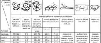
Features of SKD-6 maintenance
Before harvesting, it is important to assess the condition of both the equipment itself and the crop requiring processing. Depending on this, specific working tools are selected and configured.
About adjustment
First, the combine must travel 50-100 meters. Then he is forcibly stopped. This allows you to control the quality of work and make additional adjustments if necessary.
There are several reasons that equipment may malfunction, even with preliminary adjustment:
- Unevenness of the field.
- Clogging.
- Stalky.
The bunker uses certain patterns depending on how much grain is lost.
Sometimes the equipment is checked twice every day. The main reason is changes in humidity levels. If the plot is seeded, it is recommended to use combines that have harvested no less than 100 and no more than 350 hectares of crops. Then the percentage of microdamage and fragmentation decreases. The manufacturer produces a special bag with tools to help with adjustments.
Mode Determiner – part of the device that contains information regarding the pre-type setting. The corresponding designations are placed on the internal and external disks with which the system is supplied.
Preliminary work is easy to do - just align the marks of the disks inside and outside.
On eliminating the main defects in bridges
The following defects are more common in bridges:
- The appearance of parts with kinks.
- Increased noise.
- The appearance of extra knocks.
- Operation of parts with high heat.
- Carrying out adjustments with violations.
Do not forget that literally every part and mechanism is subject to serious wear and tear during operation.
The combine is designed to work with various crops
Rear axles work with approximately the same problems, only the rear axle, transverse link and swing arms may be bent in addition. The reason is long-term operation under unacceptable load, untimely use of oil.
To restore technical characteristics, the front and rear axles are disassembled, for which special stands are used. It is allowed to use the same techniques as in the case of conventional gearboxes in modern cars. Specific operations depend on which part broke and what damage appeared.
Welding and tapping are standard procedures for situations where threads, external or internal, are damaged. Processing takes place for normal or enlarged sizes. Templates, rulers or squares help determine the bent and twisting of the axles located at the rear or front.
Self-propelled, wheeled, double-drum, designed for harvesting cereal crops by direct and separate combining. Using additional accessories, a combine can be used to harvest grass seeds, corn for grain and silage, sunflowers, soybeans, legumes and cereals. To harvest the non-grain part of the crop, it is equipped with a stacker. It consists of a reaping part, a thresher (with a double-drum threshing apparatus, separating, cleaning and transporting devices), a hopper with an unloading device, a motor unit, a power transmission, a chassis, a cabin with a control platform, a hydraulic system, electrical equipment and an alarm system.
The reaping part includes a header and an inclined chamber mounted on the thresher. The header body is hinged on the inclined chamber at three points on a central spherical hinge and two hinged spring blocks and is balanced by these springs. Thanks to this, the soil relief is copied in the longitudinal and transverse directions. The cutting apparatus, auger, reel and drive mechanisms for these working parts are mounted on the header body.
The reel is universal, with an eccentric mechanism and spring tine fingers. It is driven by a double-circuit chain transmission from the upper pulley of the reel speed variator.
The feeder chamber consists of a housing and a chain-slat conveyor. The body is pivotally connected to the receiving chamber of the thresher. The cutting apparatus has single forged steel fingers with notched liners.
The thresher includes a receiving beater, a double-drum threshing and separating device, a straw walker, cleaning, transport devices, drives and mechanisms for adjusting the working parts. The receiving beater blades are located tangentially.
The threshing and separating device consists of a first threshing drum, a concave of the first drum, an intermediate beater, a separating grid of the intermediate beater, a second drum, a concave of the second drum with a guide grid and a breaker beater. Threshing drums - beaters. The technological process of threshing and separation in a double-drum thresher occurs in two stages. The first stage of threshing of the grain mass takes place in the first threshing apparatus, the drum of which, at a reduced rotation speed and increased gaps between the whips to the concave slats, threshes the ripest, largest and most easily processed grain with minimal damage. The second stage occurs in the second threshing apparatus, the drum of which operates in a more rigid mode (increased rotation speed and smaller threshing gap).
The rotation frequency of the threshing drums is changed by a hydromechanical device. The variator of the first drum is located on the left side of the thresher, the second on the right. The variators are controlled by hydraulic cylinders from the combine operator's workplace.
The threshing and separating device is equipped with a mechanism for reverse scrolling of the first drum. Four-key straw walker. The separating surface of the first cascade of straw walker keys has been changed (unlike the keys of the SKD-6 straw walker).
The cleaning system includes a screen, a double-sieve mill with an upper sieve extension and a fan. The gaps of the sieve blinds and extension, as well as the rotation speed of the fan impeller, are adjustable. The combine (unlike the SKD-6) is equipped with a cleaning system reinforced with a wind grill. Includes new screens, extension, modified rear screen hangers. The combine thresher is equipped with a post-threshing device.
Grain and grain elevators are scraper elevators with top feed. Grain tank with increased capacity. It has distribution and unloading augers, a vibrator to speed up the unloading of grain. The hopper lid is detachable. The unloading auger is moved from the transport position to the working position and back by a hydraulic cylinder without a latch, and is equipped with a damper controlled from the operator’s workplace. The inclined part of the unloading auger has been extended. The auger drive is autonomous, directly from the engine. Mounted straw stacker, with double-acting hydraulic cylinders, with mechanical filling of the chamber and straw pre-pressing, with a capacity of 9 cubic meters. The drive of the straw filler is V-belt.
The combine is equipped with a motor unit with a four-cylinder SMD-22 engine. which includes an engine air cleaner air intake, a muffler, quick-detachable air ducts, air cooling systems, a clutch with a plate connection between the flywheel and the drive discs, and a threaded connection of oil lines to the oil cooler. The engine is installed on the roof of the thresher behind the hopper parallel to the axis of the drive wheels and mounted on the sub-motor frame on shock absorbers. Started by starter motor.
There is a drive wheel axle with a left-hand gearbox and a single-circuit variator for the chassis drive. A widened steering axle was introduced.
A cabin with a softened ceiling, a door, seals and oversized side windows is located on the driver's platform. Equipped with a soft seat and an additional folding one, a ventilation system with purified air supply, an electric windshield wiper, electric lighting, a thermos for drinking water and a first aid kit. A heater-cooler can be installed in the cabin. The ceiling and panels are covered with soundproofing material. All the main combine controls, instruments and control lights are located in the cab. The steering is hydrostatic. Steering column with adjustable tilt angle.
The electrical equipment system is single-wire, direct current, voltage 12 V. Alternating current generator with built-in rectifiers. The hydraulic system consists of two independent systems (main and steering). There is an autonomous overflow section.
The hydraulic system lifts and lowers the header and reel, moves the reel on supports, cleans the air intake, accelerates the unloading of grain from the bunker using a vibrator, moves the unloading auger from the transport position to the working position and back, changes the speed of the combine and the rotation speed of the reel, closes the stacker valve and turning the steered wheels.
SPECIFICATIONS
| Working width, m | 4.1, 5, 6 |
| Throughput, kg/s | 6 |
| Productivity per hour of main time (when harvesting upright wheat with a yield of 40...50 c/ha and a humidity of 10...18%), t | 7…9 |
| Speed, km/h | |
| working | 1,04…7,2 |
| transport | up to 20 |
| Cutting height control limits, mm | 50…180 |
| Engine | |
| brand | |
| power, kWt | 103 |
| Engine crank painting frequency s-1 (m-1) | 33,3 (2000) |
| Thresher width, mm | 1200 |
| Thresher type | double drum |
| Drum diameter (first/second), mm | 550/550 |
| Drum shaft rotation speed, s -1 (min -1) | 7,3…22,5 (43,8…1350) |
| Angle of drum deck wrap, degrees | 127 |
| Straw walker key length mm | 2862 |
| Grain bin capacity, cubic meters. | 4.5 |
| Productivity of the unloading auger when unloading wheat, kg/s | 17.0 |
| Track, mm | |
| driving wheels | 2419 |
| managed | 1215 |
| Tire pressure, mPa | |
| driving wheels | 0.23 |
| managed | 0.21 |
| Ground clearance, mm | 380 |
| Overall dimensions with a 5m wide header in working position, mm | 10640x7510x3800 |
| Weight, kg | 9400 |
In pre-revolutionary Russia there was no production of combine harvesters. In the USSR, culture arose in the late 20s and early 30s. In 1930, production of Kommunar combines began in Zaporozhye. In 1932, the production of these combines was organized in Saratov. In 1931-32, the production of trailed grain harvesters S-1 began. They passed 2.5 kg of grain per second through a thresher and harvested, in addition to grain, sunflower, corn, millet and other crops. During the pre-war years, combine factories of the USSR (mainly Rostselmash and Zaporozhye Kommunar) produced almost 200 thousand combines for agriculture, which played a big role in the mechanization of harvesting.
Combine harvester construction reached new powerful developments in the USSR after the Great Patriotic War of 1941–45. A clearer specialization of agricultural engineering plants was carried out; The main enterprise of the Soviet combine harvester industry was the production of trailed combine harvesters S-6 and RSM-8. From 1947 to 1956, Taganrog, Tula and some other plants produced self-propelled S-4 combines, and in 1956-58 - modernized S-4M combines. In 1958, the Central Committee of the CPSU and the Council of Ministers of the USSR adopted a resolution to stop the production of trailed grain harvesters and to organize the production of more productive self-propelled combines. By this time, a model of the SK-Z self-propelled combine had been created and the production of combines began at the Taganrog Combine Plant. Since 1962, these factories began to produce self-propelled combines.
Here are the most popular options:
SK-3
At one time it became a real breakthrough.
Self-propelled harvester, 3rd model. Soviet grain harvesting machine, which was created by the GSKB for self-propelled grain combines and cotton harvesting machines in the city of Taganrog. The project was led by Canaan Ilyich Izakson. The car was produced from 1958 to 1964. In total, 169 thousand combines were created. This was the first Soviet combine harvester equipped with hydraulic power steering. SK-3 was also awarded a diploma from the Brussels exhibition.
SK-4
Received worldwide recognition.
Self-propelled combine, 4th model. As you might guess, it replaced an older model - SK-3. The machine was produced from 1964 to 1974 at the Taganrog Combine Harvester Plant, as well as at Rostselmash. The grain harvester received an award from the Leipzig International Trade Fair, as well as awards from trade fairs in Brno and Budapest. The team developing the machine under the leadership of H.I. Izakson was awarded the Lenin Prize.
SKD-6 "Sibiryak"
It was a great car.
A two-drum Soviet combine harvester, which was produced from 1981 to 1984 at the Krasnoyarsk Combine Harvester Plant. The car was a product of a deep modification of the SKD-5 “Sibiryak”, which was produced since 1969 and, despite its high reliability, became obsolete by the 80s of the 20th century. The machine had many “special” modifications, including for harvesting rice, working in areas without black soil, and a model with an extended track.
Yenisei 1200
Reliable and hardy cleaner.
Even young people should remember the combine harvester with the beautiful name “Yenisei” well from their childhood. The fact is that production of the car began in 1985. The combine was suitable for harvesting a wide variety of crops, including sunflowers, herbs, legumes and cereals. The machine could also harvest crops in “hard-to-reach” areas of the field.
Don-1500
Everyone remembers this combine.
Perhaps the most popular combine harvester in the CIS after the collapse of the Soviet Union. The car began mass production in 1986. For objective reasons, the car was used for a very long time in the former republics of the union. The widespread abandonment of the combine harvester began only in 2006, when it was quickly replaced by more advanced imported and domestic models.
KSG-F-70
A machine for working in difficult conditions.
A very interesting example. A Soviet tracked combine harvester, which was developed specifically for working on waterlogged soils. For the most part, the machine worked with forage crops: grass and corn. The Donselmash combine was produced in the city of Birobidzhan. Most of these machines were in service with Far Eastern farms.
Description of models
Basic modifications of SKD combines were equipped with a wheeled chassis with pneumatic tires. There were versions designed for rice harvesting, which had a tracked undercarriage. This design provided increased maneuverability and reduced specific ground pressure.
A header consisting of a header and an inclined tray is installed on the front of the machine. The header body is mounted on the tray through hinged supports and balancing springs. This joint design ensures copying of the ground topography during operation in the longitudinal and transverse directions. The header body is designed to accommodate the cutting tool, reel and auger mechanism.
The machines use a reel with an eccentric mechanism.
The drive is carried out by a chain gearbox. The collected material passes through the header mechanisms and then enters the feeder chamber, which is equipped with a plate conveyor belt. The cut stems fall into threshing drums, after which a straw and grain separation apparatus is installed. The machine is equipped with a blower, which additionally cleans the grain from impurities.
The waste is discharged onto the ground surface through a stacker, and the grain is stored in an on-board storage hopper. The design of the unit has an automatic alarm that is triggered when it is full.
SKD-5
The machines used a 4-cylinder diesel engine SMD-18KN with a power of 100 hp. With. The engine was equipped with a turbocharger without a compressed air cooling system. The power unit is equipped with a single-disc dry clutch with a mechanical drive from a pedal located in the operator's cabin. The transmission includes a 3-speed gearbox integrated into the drive axle design. Torque is transmitted to the axle shafts through a bevel gearbox equipped with a differential. Additional planetary gearboxes are installed in the hubs.
See » The most popular Russian combines from Soviet times to the present day
The steering on early cars was mechanical, later a hydraulic booster appeared. Hydraulically driven drum brakes are installed only on the drive axle. To hold the combine in the parking lot, a mechanically driven band brake is used.
Machine Specifications:
- operating speed - 1.2-8.46 km/h;
- productivity (hourly) - 7.6 tons;
- travel speed - 21 km/h;
- storage chamber capacity - 9 m³;
- length - 9.8-11.19 m;
- height - 4.0 m;
- width (in working condition) - 3.5-4.92 m;
- curb weight - 7450 kg.
There was a modification of the SKD-5M, which was distinguished by the use of a number of components unified with the Neva combine. The vehicle used a modified cabin configuration and an enlarged grain bin. The entire design of the combine has undergone modifications, making it more reliable and productive.
SKD-6
The combine is a modernized machine of the SKD-5 model, which began to use a header with a working width of 5 m. To increase the productivity of the machine, it was necessary to install an improved power unit. The equipment used a 140-horsepower SMD-20 diesel engine.
Purpose and content of the work
. To consolidate knowledge of the use of combine harvester controls and instruments. Consider the features in the arrangement of instruments and controls on various models of combines. Check and adjust the control mechanisms of the working bodies of combine harvesters. Study the structure of the automatic threshing load regulator (ARZM) and the driver’s seat.
Workplace equipment
. Spring dynamometer for 5 kgf (49.03 N), ruler 0-300 mm, caliper ShTs-P-0.1-200, probe (set No. 2), indicator ICH 05 class. 1, a set of feeler gauges for checking gaps in the threshing apparatus, an ignition key for the SKD-5 instrument panel, a 500 g bench hammer, an A175x0.7 screwdriver, a jack, a stand for the combine. Wrenches 8X10; 12X14; 17X19; 22X24; 27X30; 32X36; 36X41; wrench for round nuts 46-52 mm.
Work sequence
. Inspect the cabins of the combines and pay attention to the fact that all combines have the same arrangement of all pedals and gear shift lever. Note that on the SK-5 and SK-6 combines, levers 1 (Fig. 100, 101) for regulating the fuel supply, lever 16 (see Fig. 100) and lever 7 (see Fig. 101) for turning on the drive of the combine mechanisms are located similarly. , handle 23 (see Fig. 100) and handle 13 (see Fig. 101) for releasing the parking brake.
Pay attention also to the fact that on the SK-6 combine, the lever 14 for turning on the unloading auger, the handle 17 for regulating the speed of the first drum and the lever 16 for adjusting the gaps in the threshing apparatus are located to the left of the driver. On the SKD-5 and SK-5 combines, these levers are located to the right of the combiner. Please note that there are two instrument panels installed in the cabin of the SK-6 combine. On the left panel 15 (see Fig. 101) all the signal lights and alarm switches are installed, on the right panel 5 there are instruments that control the operation of the engine and the tachometer of the second drum.
On SK-5 and SKD-5 combines, all instruments are concentrated on one panel (Fig. 102, 103). The inscriptions explain the purpose of each of the switches and devices.
Find on the SK-5 and SK-6 combines equipped with automatic thresher loading regulators, the main components and controls for this regulator.
Inspect the ARZM mechanisms on both combines and make sure that they are basically the same.
Using Fig. 104, find on the SK-5 and SK-6 combines the grain loss indicator units (abbreviated as UPZ): loss converters 1 and 6, measuring unit 2 and loss indicator device 5.
Find cabin heaters on combines and consider how heat is removed from the engines. Consider fans for blowing the driver and for centrifugal air purification.
Check the availability of tools and accessories and begin work.
Assembly and adjustment of bridges
Assembly and adjustment of the front axle are carried out on disassembly stands.
The front axles of combine harvesters are assembled in this sequence. The front axle is placed on a stand. The steering arms are secured in the pivot axles, the axles are installed on the axle, and the transverse steering rod is mounted. Install support brake discs and brake pads. The brake drums and wheel assemblies are installed. Check the correct installation of the wheels and adjust their toe angle and maximum steering angle. A certain camber angle of the front wheels and the angle of rotation of the kingpin back are provided for by the design of the front axle and steering axles.