How much does a new T 25 tractor cost?
Weight - 1550 kg. The car comes with all documents and instructions. Price - about 600,000 rubles without attachments. The next worthy analogue of the Russian tractor T
—
25
is the Chinese tractor manufacturer Xingtai, which produces units of various capacities.
Interesting materials:
How many ml in one glass? How many ml of wine is poured into a glass? How many mm should a lymph node be? How many mm are in a stack? How much milk for 1 kg of parmesan? How much milk is needed to make condensed milk? How much milk is in one Faceted glass? How much milk is in a 250 ml glass? How long should you freeze meat for a dog? How much brain does an octopus have?
Design of the power take-off shaft of the T-25 tractor
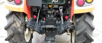
PTO — The power take-off shaft of the T-25 tractor transmits rotation from the engine to mounted and trailed mechanisms. The T-25 tractor is equipped with a shaft with a dependent drive; before turning it on or off, you need to stop the tractor. The PTO is located at the rear of the tractor. When the shaft is not used, its tail is closed with a special-purpose cap.
Design
The power take-off shaft of the T-25 tractor is the switching mechanism and shaft, which are located in the hydraulic lift of the intermediate shaft, which is mounted in the main gear. The PTO and the main one are equipped with toothed rims, which are connected after switching on by a gear coupling. On the neck of the main shaft there is an inner ring of the ball bearing, which is pressed all the way into the ring gear and secured with a retaining ring.
The outer ring of the bearing is located in the bore of the housing part of the main gear. The displacement of the axes of the outer ring is limited by the bushing and shoulder, which center the hydraulic lift body in relation to the main gear. On the end side of the intermediate shaft there is a boring with a pressed-in bronze bushing, which represents the front support for the shaft.
There are special drillings for special purposes in the shaft, through which oil is supplied to lubricate the bushing. At the front of the splined end of the main shaft there is a bushing that connects the shaft to the transmission drive shaft. The second shaft support is a bearing, which is installed in the bore of the hydraulic lift body between the retaining ring and the seal socket.
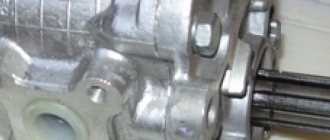
The splined end is bolted to the hydraulic lift body. When the PTO is put into operation, a part is installed on its splines that connects the shaft to the drive of the equipment used. The radial groove is used to fix shaft-mounted products.
Switching device
The shaft engagement mechanism includes a lever welded to the axle and fork. The fork is fixed to the axis with a bolt; the fork horns contain crackers that fit into the gear coupling. A flat spring is attached to the lever, at the end of which a plastic handle is mounted. In order to turn on the shaft, you need to move the handle back until the springs pass through the boss on the body of the hydraulic lift.
The fork will move the coupling forward, as a result of which the ring gears of these shafts will unite. The shaft is turned off and on only when the clutch is disengaged. All components and mechanisms of the power take-off shaft on the T-25 tractor are lubricated with oil that comes from the gearbox and do not require additional lubrication.
Do-it-yourself heating of the T 25 tractor cabin video
Cabin | Topic author: Calanthe
Dmytro (Avital) https://olx.ua/uk/i2/obyavlenie/traktor-t-25-kabina-ID..
Dmytro (Avital) https://olx.ua/uk/i2/obyavlenie/karkas-tenta-kabina-na..
Tags: Do-it-yourself heating of the T 25 tractor cabin video
Test stove tractor T 25
Guys, tell me how to install a stove in the T-25, heating using oil from the engine or hydraulics, the stove is from a field. | Topic author: Vasily
Diana Have you ever heard of such a thing as blood pressure?
Vera Isn't it easier to think about exhaust gases?
Maria I don’t understand, do you mean a tank or a tractor?
Vitaly Yes, install a potbelly stove, and don’t worry
Nadezhda It is necessary to start the oil from the engine, and not from the hydraulics, and most likely the heater radiator will not withstand the pressure Anatoly, usually install oil radiators, they are designed for this.
Lydia and not easier from the cooling system. but from hydraulics .. I’m the first to hear this .. that hydraulics provide heat
Alla hydraulics cannot be broken, but you can connect current to the engine instead of the oil cooler. if he is. there is still a ribbed coil on the side of the cylinders. but I think it won’t help much in winter and air-cooled engines don’t heat up
Zoya A T-25 air cooling?? ? You have two options: 1. lay a reinforced hose with a diameter of 100 mm from the air cooling fan into the cabin. You can go straight to the engine. You can adjust it simply by plugging the hole. 2. More powerful generator and electric blower.
Elena, you can get a gasoline one from a Cossack, I think this is the cheapest option, or you can get an autonomous one, it’ll cost about 10 thousand, but you’ll be like on the Canary Islands!
Page from the section → The power of technology ↓ You might be interested ↓
Source
Repair manual . — https://aido.ucoz.ru/
Year of release: 1972 Author: Gerasimov A.D., Golubchik S.F., Kulchitsky R.I., Khodulin Yu.A., Tsyganenko V.R., Shaanov A, I. Genre: Repair and operation manual Publisher: Kolos Format: DjVu Quality: good Number of pages: 175 Language: Russian The book examines the design and operation of the T-25 tractor.
The issues of machine care are covered in detail, recommendations are given for the most rational use of the tractor in all work, as well as for aggregating it with various agricultural equipment. machines and tools. is a wheeled universal machine of the 0.6 t class with a semi-frame, rear drive and front steered wheels. Reversing all main gears allows you to use both forward and reverse gear when working. The tractor track and ground clearance can be adjusted. The D-21 engine runs on diesel fuel and develops a power of 20 hp. With. at 1600 rpm. The T-25 tractor is used in gardens, vegetable gardens and small field plots for applying fertilizers, controlling weeds and pests, sowing, planting and harvesting vegetables, harvesting hay, and plowing light soils. In addition, the tractor is used to drive stationary machines, for light loading and earth-moving work, in construction and for transport. The T-25 tractor was created on the basis of the previously produced DT-20 machine. The book is intended for machine operators working on tractors. The T-25 tractor is a wheeled universal machine of the 0.6 t class with a semi-frame, rear drive and front steered wheels. Reversing all main gears allows you to use both forward and reverse gear when working. The tractor track and ground clearance can be adjusted. The D-21 engine runs on diesel fuel and develops a power of 20 hp. With. at 1600 rpm. The T-25 tractor (Fig. 1) is used in gardens, vegetable gardens and small field plots for applying fertilizers, controlling weeds and pests, sowing, planting and harvesting vegetables, harvesting hay, and plowing light soils. In addition, the tractor is used to drive stationary machines, for light loading and earth-moving work, in construction and for transport. The T-25 tractor was created on the basis of the previously produced DT-20 machine. As a result of the modernization, the engine was replaced on the tractor, a permanently closed clutch, an inclined steering column, more advanced floating brakes were introduced, all controls were changed, and a more comfortable sprung seat was installed. The tractor has modern external shapes. Thanks to an increase in engine power and a slight increase in operating and transport speeds, the productivity of the unit has increased. A more convenient location of the controls improved working conditions and made it easier to operate the tractor. The general structure of the tractor is shown in Fig. 2. Engine. The T-25 tractor is equipped with a two-cylinder four-stroke air-cooled D-21 engine produced by the Vladimir Tractor Plant. The engine has a compression ignition operating process and direct fuel injection into the combustion chamber located at the crown of the piston. It starts on diesel fuel with an electric starter.
Chapter IX
WORKING AND AUXILIARY EQUIPMENT OF TRACTOR T-25
POWER TAKE-OFF SHAFT DRIVE OF TRACTOR T-25
To transmit rotation from the engine to the active working parts of agricultural machines and implements, the T-25 tractor is equipped with a power take-off shaft (PTO).
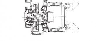
The power take-off shaft drive consists of an intermediate shaft 8 (Fig. 72), installed in the main gear housing, shaft 18 and its activation mechanism, located in the lower compartment of the hydraulic lift housing. The intermediate shaft and the power take-off shaft are made integral with the toothed rims, which are connected by a gear coupling 22 in the engaged position of the shaft.
The inner ring of the double-row ball bearing 9 is pressed onto the journal of the intermediate shaft until it stops against the gear ring and secured with a spring retaining ring 24. The outer ring of the bearing is installed in the bore of the main gear housing. The outer ring is kept from axial displacements by the housing flange and the bushing 10, which simultaneously centers the hydraulic lift housing 20 relative to the main gear housing. In the annular groove of the bushing there is a spring ring 11, sandwiched between the wall main gear and the hydraulic lift body.
A bronze bushing 23 is pressed into the bore at the end of the intermediate shaft, which serves as the front support for the power take-off shaft 18. To supply oil to the rubbing surfaces of the bushing, special drillings are made in the shaft. A sleeve 25 is riveted to the front splined end of the intermediate shaft 8, with which the intermediate shaft is connected to the drive shaft of the additional transmission.
Bearing 14, which serves as the second support for shaft 18, is installed in the bore of the hydraulic lift housing between the spring retaining ring 13 and the seal socket 19. The inner ring of the bearing is pressed onto the shaft journal until it touches the outer retaining ring 21 and is clamped by a nut 15 with a lock washer. The splined end of the power take-off shaft is closed with a protective cap 17, bolted together with the oil seal socket to the hydraulic lift body.
When working with the PTO drive, the protective cap is removed, and parts that connect the shaft to the drive of the agricultural machine are installed on the shaft splines. The radial groove on the splined end of the shaft is intended for fixing parts installed on the shaft.
The mechanism for engaging the power take-off shaft consists of a fork 2 and a lever 5 welded to the axis 3.
The fork 2 is secured to the axis with a bolt 12, and in the drillings of the fork horns, crackers 1 are installed, which fit into the radial groove of the gear coupling 22.
A flat spring 6 is riveted to lever 5, at the end of which a plastic handle 7 is attached. To engage the PTO, you must move the handle back until the spring passes through the boss on the hydraulic lift body. In this case, the fork 2 will move the clutch 22 forward and connect the gear rims of the intermediate shaft 8 and the power take-off shaft 18. In the off position, the gear coupling is completely located on the teeth of shaft 18 and therefore rotation is not transmitted from the intermediate shaft. Engaging and disengaging the PTO should only be done with the clutch disengaged. The bearings and gears of the power take-off shaft are lubricated with oil coming from the main gear housing and do not require additional lubrication. Two self-clamping oil seals 16 protect against oil leakage from the PTO cavity. The felt ring seals the bore under the release lever axis.
Rice. 72. Power take-off shaft drive:
1 — shutdown fork cracker; 2 — PTO release fork; 3 — lever axis; 4 — felt seal; 5 — PTO release lever; c - flat spring of the release lever; 7 — lever handle; a — intermediate shaft; 9 — double-row ball bearing; 10 — centering sleeve; and and 13 — retaining rings; 12— bolt securing the shutdown fork; 14 - ball bearing; 15 - nut; 16 — self-clamping oil seal; 17 — protective cap; 18 — power take-off shaft; 19 — seal socket; 20 — hydraulic lift housing; 21 — retaining ring; 22 — gear coupling; 23 - bushing; 24 — retaining ring; 25 — splined bushing.
content .. 91 92 95 ..
