Combine harvesters
Type of combines
The combines are designed for harvesting cereal crops using direct and separate combining.
With additional accessories, a combine can be used to harvest cereals and oilseeds, corn for grain, and grass seeds. Self-propelled, trailed and semi-mounted combines are used. According to the direction of flow of plant mass and heap relative to the direction of movement, T-, L- and U-shaped schemes of combines are distinguished.
The T-shaped scheme of combines is used in self-propelled combines. In them, the cut plants come from the right and left sides of the header to its central part, where the direction of the flow changes by 90˚. Harvesters made according to this design are characterized by high maneuverability and good visibility of the area of cut plants. However, in such combines the drive of the working parts is more complicated, and the overall dimensions (height and length) are increased.
L-shaped patterns are used in trailed or mounted combine harvesters. Trailed combines are less maneuverable than self-propelled ones; when harvesting, they increase the metal turnover across the field. Compared to self-propelled combines, the use of trailed combines results in lower operating costs and capital investments.
The U-shaped scheme is implemented in combines, in which the longitudinal axis of the thresher is parallel to the header. This scheme is compact, less material-intensive, and convenient for maintenance. The use of axial rotary threshers expands the capabilities of U-shaped combine harvesters, especially small ones.
Depending on the design of the working parts of the threshing machine, a distinction is made between drum-straw walker (classical design) and axial-rotor combines, in which the grain is threshed and separated from the resulting heap by a rotating rotor and a casing (deck) bordering it.
The main parts of combine harvesters: a reaping part, a pick-up, a thresher, a hopper with a device for unloading grain, devices for collecting, crushing, compacting or scattering the non-grain part of the crop, a cabin, control systems and monitoring the operation of the combine, as well as devices for harvesting various crops.
Combine Harvester Workflow
When a combine with a classic thresher moves, the dividers 1 of the header (Fig. 1) separate a strip of stems equal to the working width of the combine, and the reel bars 2 capture a portion of the stems from this strip and bring it to the cutting device 3. The cut mass of the reel bars is fed to the auger 4. The right and left blades of the auger move the grain mass to the middle, where it is captured by the fingers of the middle part of the auger and fed from below to the beater 5 spacers with retractable fingers (in some combine designs such a beater is not used). The fingers of the beater 5 pull apart the mass fed by the auger, reducing the “dead” zone between the auger and the floating conveyor 6, which increases the uniformity of the flow. The slats of the lower branch of the conveyor 6 capture the mass and, pressing it against the bottom of the feeder chamber housing, move it to the threshing device. In a number of combines, a receiving beater with blades is installed between the floating conveyor and the threshing device, guiding the stalks to the threshing-separating device. It includes drum 7 and deck 8 (concave), which disrupt the connection between the grain and the ear. Part of the grain (80...95%) and small impurities (chaff) pass through the concave holes and enter the transport board 9.
The remaining mass (coarse heap) coming out of the threshing space is directed by the beater 10 to the straw walker 17, where free grain is released from the straw by shaking. A small heap (grain, chaff) that has fallen through the holes of the straw walker is poured onto the transport board through the trenches of the keys.
The straw, moved by the straw walker to the exit, arrives at the rakes of the straw filler 21. The teeth of the rakes capture a portion of straw and move it into the stacker chamber 20. When the chamber is filled with straw to the upper level, the rakes begin to compress the mass. If straw is removed by chopping or pressing, then a chopper is installed instead of a stacker.
Rice. 1. Working process of the Don-1500B combine: 1 - dividers; 2 - reel; 3 — cutting apparatus; 4 - auger; 5 — spacer beater; 6 - floating conveyor; 7 - drum; 8 — deck (concave); 9 — transport board; 10 — impact beater; 11 — fan; 12 — pre-threshing device; 13 — grain elevator; 14, 15 - upper and lower sieves, respectively; 16 — grain elevator; 17 — straw walker; 18 — extension of the upper sieve; 19 — chaff filler; 20—accumulator; 21 — straw filler; 22 — grain bunker; 23 - distribution screw
Grain and chaff pass between the fingers of the transport board and fall onto the front part of the upper sieve 14, and long impurities (breaks), sliding along the fingers of the transport board grid, arrive closer to the middle of the sieve. Light impurities are blown out by the air flow coming from the fan 11, and then pushed into the stacker chamber by the rake of the floor filler 19.
Grain and some impurities are processed on the upper 14 and lower 15 sieves and, passing through them, enter the grain auger and elevator 13. The grain elevator and distribution auger 23 direct the grain into the hopper 22. When the hopper is filled, the grain is unloaded into vehicles. Large impurities (unthreshed ears) come off the sieves. The discharge from the upper sieve partially falls through the holes of the seal 18, enters the lower spikelet auger, and then is fed by the elevator 16 to the pre-threshing device 12. The pre-threshed spikelets and grain go to the sieves.
When combining separately, pick-up platforms are used, installed instead of the header, or finger-type or drum pick-ups with spring fingers are hung on the header. The selected plant mass is then fed to the auger and working parts.
Combines with a drum-deck threshing-separating device and a straw walker are widely used. The working process proceeds reliably, and the throughput reaches 5 kg/s per 1 m of thresher width. By equipping these combines with additional attachments, a variety of crops can be harvested. However, a further increase in the productivity of such combines causes an unacceptable increase in their overall dimensions and weight.
The increased weight of the combine leads to significant environmental disturbances: the soil becomes over-compacted, the ruts deepen, roads, bridges, etc. are destroyed. Due to the increased size of the straw walker, inertial loads increase, reducing the reliability of the machine and increasing economic indicators. The large overall dimensions of the combine impair its maneuverability and complicate maintenance and repair work.
content .. 1 2 3 7 ..The device of the drive and executive body of the Ural-10A combine
The dual planetary-disk executive body of the combine consists of two independent bodies (left and right), kinematically connected through a common gearbox
Rice. 2.12 Scheme of a set of cutters: a) on a cutter disk; b) on the tap
Rice. 2.13 Diagram of a set of cutters: a) on the side cutters of the berm body; b) on the auger
portable rotation located between them (Fig. 2.15). Both executive bodies of the combine and the portable rotation drive are mounted on a common platform, which is hinged with the help of two hydraulic jacks and an axle on the front frame of the scraper conveyor.
The executive body can be assembled into one of three standard sizes of excavation with a height of 2.2; 2.4; 2.6 m. The transition from one standard size to another is carried out by extending the handles of the transfer gearbox and changing the position of the axis of the executive body using a movable platform on which the executive body is mounted. Each executive body (left and right) of the combine consists of an executive body gearbox and a transfer gearbox, two cutting discs, a piping device and a BA02-315M8 electric motor.
The executive body of the combine carries out the destruction of the face with two pairs of cutting discs, each of which is equipped with eleven D6-22 cutters and two burrs equipped with six pairs of D6-22 cutters.
The rotation of the cutting discs, just like on the Ural~20A combine, is carried out simultaneously in two directions: around their own (relative to the movement) and the main (transferable movement) axes.
The actuators, rotating in opposite directions (transferable motion), move the destroyed mass to the receiving part of the scraper conveyor.
The rotation of the cutting discs is provided by electric motors VA02-315M8 (relative movement) and VRP 200L4P (portable movement) through the gearboxes of the executive body, dispensing and portable movement.
The intakes are driven, unlike the Ural-20A combine, only with the help of a portable electric motor with a rotation speed of n = 4.75 min'1, because They are mounted rigidly on the transfer gear housing. The kinematic diagram of the actuator drive is shown in Fig. 2.16. Tables 2.5 and 2.6 show the characteristics of the gear wheels of the actuator drive (relative and portable motion) and bearings, respectively.
The executive bodies of the combine (left and right) in the working position are rotated relative to each other at an angle of 90°. Before
By driving the combine away from the excavation, the executive bodies are deployed to a position that prevents the cutting tool from touching the walls of the excavation. The turn is carried out after desynchronization of the portable movements of the left and right
Rice. 2.15. Drive and executive body of the Ural-1 OA combine: 1 - cutting discs; 2 — transfer gearbox; 3 — gearbox of the executive body; 4 — portable rotation gearbox; 5 - electric motor
Rice. 2.16. Kinematic diagram of the drive of the executive body of the Ural-10A combine: 1-5, 7-13, 17, 18, 20, 22-24, 27-29, 32, 33 - gear wheels; 6, 14, 15 — gear couplings; 16,19,21, 25,26, 30, 31,34-44 - bearings
Table 2.5
Position in Fig. 2L6
| Number of teeth | Module, mm | Position in Fig. 2L6 | Number of teeth | Module, mm | |
| 1 | 31 | 14 | 14 | 18 | 6 |
| 2 | 25 | 14 | 15 | 32 | 3 |
| 3 | 16 | 16 | 17 | 12 | 6 |
| 4 | 16 | 14 | 18 | 21 | 6 |
| 5 | 21 | 16 | 20 | 66 | 6 |
| 6 | 31 | 6 | 22 | 66 | 6 |
| 7 | 65 | 6 | 23 | 27 | 6 |
| 8 | 65 | 6 | 24 | 12 | 6 |
| 9 | 65 | 6 | 27 | 25 | 14 |
| 10 | 37 | 14 | 28 | 17 | 10 |
| 11 | 90 | 6 | 29 | 44 | 10 |
| 12 | 37 | 6 | 32 | 13 | 14 |
| 13 | 15 | 6 | 33 | 25 | 14 |
Table 2.6.
| Position in Fig. 2.16 | № iodshipn ika | GOST | Number iodshini ncov | Positions in Fig. 2.16 | >»2 iodshipn ika | GOST | Number IODSHIPN ncov |
| 16 | 130 | 8338-75 | 3 | 36 | 3526 | 5721-75 | 2 |
| 19 | 3610 | 8328-75 | 6 | 37 | 2097960 | 6364-78 | 2 |
| 21 | 3610 | 5721-75 | 6 | 38 | 236 | 8338-75 | 2 |
| 25 | 3528 | 5721-75 | 1 | 39 | 2097736 | 6364-78 | 2 |
| 26 | 3620 | 5721-75 | 8 | 40 | 7536 | 333-79 | 8 |
| 30 | 3626 | 8338-75 | 1 | 41 | 3536 | 5721-75 | 2 |
| 31 | 3620 | 5721-75 | 1 | 42 | 3622 | 5721-75 | 20 |
| 34 | 3524 | 5721-75 | 4 | 43 | 2097732 | 6364-78 | 4 |
| 35 | 3614 | 5721-75 | 12 | 44- | 2097968 | 6364-78 | 2 |
Table 2.7
| Position in Fig. 2.20 | Number of teeth | Module, mm | Positions on rice. | Number of teeth | Module, mm |
| 2 | 19 | 6 | 12 | 66 | 6 |
| 3 | 19 | 6 | 13 | 12 | 6 |
| 5 | 18 | 12 | 14 | 66 | 6 |
| 7 | 18 | 12 | 15 | 32 | 3 |
| 8 | 18 | 12 | 16 | 12 | 6 |
| 9 | 18 | 12 | 18 | 12 | 6 |
| — | — | — | 20 | 12 | 6 |
Table 2.8
| Position in Fig. 2.20 | Bearing No. | GOST | Number of bearings |
| 1 | 53616 | 5721-75 | 6 |
| 4 | 3620 | 5721-75 | 2 |
| 6 | 3618 | 5721-75 | 1 |
| 10 | 3622 | 5721-75 | 1 |
| 11 | 130 | 8338-75 | 3 |
| 17 | 3610 | 5721-75 | 6 |
| 19 | 3610 | 5721-75 | 6 |
executive bodies, ensured by switching gear couplings in the gearboxes of the executive bodies
The gearbox of the executive body of the Ural 10 A combine harvester (2.17) is designed to transmit rotation from the electric motors of relative and portable movements to the transfer shaft
and incisal discs. The gearbox consists of a drive shaft 14 mounted on two roller bearings in a support 13 fixed in a cast housing 12. Through a coupling half 11
The drive shaft is connected to the sun gear 10 of the T-2K-N type planetary gear, which transmits movement to three satellites 9 of the planetary gear, which are in fixed engagement with the fixed ring 8
The planetary gear carrier 7 and the coupling half 16 are secured to the shaft 6 using splines.
The gearbox has a hollow shaft 5 mounted on two roller bearings, to which a portable rotation gearbox transmits rotation through a gear wheel 4 and half-coupling 3.
With the help of keys 2, rotation from the hollow shaft 5 is transmitted to flange 1 and then to the housing of the transfer gear (transferable movement). From the main electric motor BA02-315M8, through coupling half 15, drive shaft 14, sun gear 10, planetary gear carrier 7, shaft 6 and coupling half 16, rotation is transmitted to the transfer gear gears.
The transfer gearbox of the Ural-10A combine (Figure 2.18) is designed to transmit torque from the gearbox of the executive body to the cutting discs and spools. It consists of a cast housing 8, fixed to the body of the gearbox of the executive body. Shafts 3, 5 bevel gears 4 and 2 are mounted in the bores of the housing on roller bearings. Spur wheels 6 are mounted on shafts 5. Two handles 9 are mounted on shafts 5, inside which parasitic gears 10 are located, located in
meshing with cylindrical wheels 6 and 12. The cylindrical gear 12 is fixed on the drive shaft 11 of the cutting disk 1, which is equipped with cutters of type D6-22. Cutting disks 1 receive rotation from the gearbox of the executive body through coupling 7, shaft 3, bevel wheels 2, 4, cylindrical wheels 6, 10 and 12. When adjusting the executive body to a certain standard size, handle 9 can be rotated relative to the body 8 and fixed with bolts in the desired position. position On the housing 8 of the transfer gearbox, the intake valve is secured with bolts. The mesh of bevel gears 2 and 4 is adjusted using shims.
Rice. 2.17. Gearbox of the executive body of the Ural-10A combine 1 - flange, 2 - key, 3 - half-coupling, 4 - gear, 5 - hollow shaft, 6 - shaft, 7 - carrier, 8 - crown, 9 - gear, 10 - shaft gear, 11 - cage, 12 - housing, 13 - support, 14 - half-coupling shaft, 15 - half-coupling, 16 - half-coupling
Rice. 2.18. Distributing gearbox of the Ural-10A combine 1 - cutting disk, 2 - bevel gears, 3 - ML, 4 - 5-ml bevel wheel, 6 - gear wheel, 7 - half-coupling, 8 - housing, 9 - handle, 10 - gear wheel, 11 - shaft, 12 - gear wheel
Rice. 2.19. Upper fender of the Ural-10A combine: 1 - drum, 2 - gear half-coupling, 3 - shaft, 4,5,6,7 - gear, 8 - shaft. 9 - carrier, 10,12 - sun wheel, 11 - carrier, 13 - electric motor, 14 - half-coupling, 15,16 - satellite gears, 17 - housing
In terms of purpose and design, the berm bodies of the Ural-20A and Ural-10A combines are similar. The only differences are in the fastening of the gearbox (without intermediate brackets) and augers (there are no intermediate supports 22, Fig. 2.9).
The upper fender of the Ural-10A combine (Fig. 2.19) is an independent unit with a drive and is designed to form the upper part of the excavation, which is not covered by cutting discs.
The upper fender of the Ural-10 A combine is movably mounted on the gearboxes of the executive body and can be raised or lowered using two hydraulic cylinders, which ensures the required standard size of excavation or clearance in the transport position.
Rice. 2.20 Kinematic diagram of the upper fender of the Ural-10A combine: 1,4,6,10,11,17,19 - bearings; 2,3,15 - gear couplings; 5,7,8,9,12-14, 16,18,20 - gears
The fender consists of a cast body 17, made of two handles fastened together, on which the drum is mounted. The drive of the combine harvester consists of a VRP 180S4 electric motor. The drive gearbox is mounted in one of the handles and includes two 2K-N type planetary gears and three pairs of cylindrical wheels. From the electric motor 13 through the coupling half 14 and the sun gear 12, rotation is transmitted to the first planetary gear 15. In the carrier 11 of the first planetary gear, a sun gear 10 is fixed to the splines, which meshes with three satellites of the second planetary gear 16. In the bore of the carrier 9 of the second planetary gear, the sun gear 10 is fixed to the splines shaft 8 with gear 7, from which rotation is transmitted to shaft 3 through gears 6, 5, 4. At the end of shaft 3 there is a gear half-coupling cut, which engages with gear half-coupling 2 of drum 1 of the upper fender. The second side of the drum is not driven and rests through a gear coupling on a shaft mounted on bearings in the second handle of the upper fender.
The kinematic diagram of the upper fender of the Ural-1 OA combine is shown in Fig. 2.20. In table 2.7 and 2.8 give the characteristics, respectively, of the gear wheels of the drive of the upper fender and the bearings of the Ural-10A combine.
How does an agricultural combine harvester work?
A grain harvester is an agricultural machine for harvesting cereal crops such as wheat, rye, and barley. When installing additional equipment, the unit is capable of harvesting other technical varieties of grain: corn, rapeseed, buckwheat and sunflower, legumes and small-seeded mixtures.
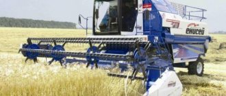
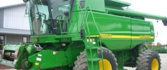
Self-propelled complexes “Don-1200”, “Don-1500” and “Vector” have become widespread among agronomists and farmers. Their productivity reaches 8-12 tons per hour, grain loss is no more than 1.5%. The complexes are used in direct and separate combining methods.
A grain harvester is a complex mechanism that performs a full technological cycle, including the following operations:
- cutting ears of grain;
- delivering them to the thresher;
- threshing grains;
- cleaning the heap;
- moving to the bunker;
- unloading grain.
Let's look at the structure of a grain harvester and the workflow from preparing the unit to its operation using the Don-1500 as an example.
Grape harvester
Rice. 4. Scheme of the technological process of a grape harvester.
self-propelled machine for cleaning technical equipment. grape varieties. It works in vineyards with row spacing of at least 2 m. The working parts of the combine are mounted on a high-clearance portal-type chassis. The combine (Fig. 4) is equipped with finger and whip shakers 1, consisting of one or two sections and equipped with impact rods made of fiberglass 2. When the machine moves over the vineyard row, the rods hit the bushes. From the impacts, the fruits fall onto the catchers 3, roll onto the conveyors 4 or into elevator buckets for feeding into the bunkers 5. During the movement, the fruits are cleaned of impurities by the air flow created by the blower fans 6. From the bunker, the berries are unloaded into vehicles traveling along the adjacent row. When harvesting difficult-to-remove grape varieties, reduce the operating speed, increase the amplitude or frequency of vibrations of the finger shaker rods, or use drum shakers. The drums perform transverse vibrations, shake the bushes, and the berries come off. They produce models that harvest grapes on the plain and areas with a slope of up to 5°, and models for working on areas with a slope of up to 12°, the latter equipped with a horizontal position stabilization system. Machine productivity is 0.4–1.0 ha/h. The completeness of harvesting from the bush is up to 99%, the completeness of catching berries is up to 99.6%. Whole bunches and berries account for up to 77% of the harvested grapes.
How the technology works
General structure of a grain combine:
- Reaper.
- Spacer.
- Tilt camera.
- Threshing and separating device (MSD).
- Bunker.
- Hoarder.
- Engine.
- Transmission.
- Chassis system.
- Hydraulics.
- Electrical equipment.
- Controls.
- Cabin.
- Electronic control system.
When harvesting separately, a pick-up platform is installed instead of a header.
Harvest dates
The best time for harvesting wheat was experimentally determined. The main harvest occurs on days 10-12 after full ripening. The grain reaches its maximum size, dries to a moisture content of no more than 20%, and the stem dries completely and acquires a golden hue.
If you start harvesting a little earlier, at the beginning of wax ripeness, the grain will be full-bodied, but not dry enough, so it will need additional drying. Delay in harvesting can lead to crop losses due to lodging of crops.
How does a combine harvester work?
The operating principle of a grain harvester is presented as follows.
The reel tilts the grain stands, and the cutting device performs the trimming. The plant mass entering the auger is narrowed and, using finger devices, is fed into the inclined chamber, then along a conveyor belt to the MSU. The receiving beater of a wheat harvester moves the raw material to the drum. Falling stones and heavy objects are thrown back into the stone catcher by screw blades and settle at the bottom.
The ears pass through the drum beats along the deck. The grains are knocked out with special notches that replace direct beats with sliding ones, reducing losses. The straw mass is transported and collides with the crossbar, and the separation process occurs. The separating zone threshes up to 100% of grain crops. Up to 80% is released from the straw mass, the remainder goes to the straw walker and fluffs up. The grains fall down, pass through the key mechanism and are cleaned on the grate, the straw enters the stacker.
The heap moves along the shaking board from the MSU and the straw walker to the finger grate. There it is cleaned, impurities are blown out by an air stream from a fan: small particles fall through the cleaning sieve and fall to the beginning of the upper element, large particles - to the middle. Through the 2/3-open blinds, grains and small spikelets fall onto the lower sieve, large residues onto the extension cord and into the spikelet auger. The grains roll down the board and enter the grain auger.
The ears of grain from the grain auger move sequentially to the grain elevator, then to the distribution auger, beater, and drum. The threshing process is repeated. The grain auger moves the raw materials into the grain elevator and bin. The chaff filler uses a compacting chamber to almost half compact the straw that has fallen into the stacker and directs the chaff to the bottom of the device. As soon as the mechanism is filled, the driver presses the pedal to unload the hay. Upon completion of the process, the stacker closes automatically.
If a chopper is installed instead of a stacker, the chaff is ground and scattered across the field.
This scheme of operation of the combine is classic.
Forage harvester
machine for mowing green crops and picking up swaths of dried seeded or natural crops. herbs, as well as for harvesting tall crops (corn and sunflower) with simultaneous chopping and loading. mass into the body of a vehicle moving nearby. It is produced in self-propelled and trailed versions, equipped with a header or windrow pick-up and a drum or disk-type chopping apparatus. Grass cutting capacity 22–40 t/h; when selecting rolls 15–70 t/h; when mowing tall crops 30–150 t/h.
Preparing for work
Bread mass cannot be standardized. A problem such as grain loss during threshing is solved by improving the design of agricultural machinery and adjusting the working parts.
Proper technical preparation of the combine for operation is the key to the uninterrupted execution of the entire technological process.
Before operating the unit, check its technical condition, completeness, and operation of all systems and units. If any malfunctions are found, they must be corrected.
- tightening fasteners;
- belt tension and chain deflections;
- location of pulleys, sprockets and circuits;
- tightness of parts;
- condition of the engine and axles;
- control pedals.
When preparing a grain harvester for operation, to reduce threshing losses, special attention is paid to setting parameters taking into account the type of crop being harvested and operating conditions. So, for wheat:
- the threshing drum is set at a speed of 900-1300 rpm;
- the main deck gap is 8-12 mm;
- sieve holes - 8-10 mm;
- fan slots - points 2-3;
- fan rotation speed - 700-850 rpm.
Direct combining
In modern agriculture, when harvesting, the direct combining method is most often used, as the most effective and convenient. Its essence lies in a single-phase mowing of the ears, followed by threshing, cleaning them from debris and transporting them to the granary. This work is most often performed by the Mega-204, Lida-1300, E-525, E-527, DON-1500, KZS-10, Mega-218, KZR-10, KZS-7 combines. Harvesting of winter wheat occurs when the grain reaches full maturity, so the harvesting period should be completed no later than a week in advance to avoid losses due to overstaying.
The popularity of the method is explained by a number of advantages:
- Low energy consumption and low cost of harvesting;
- Independence from weather conditions;
- Minimal yield loss.
Direct combining is best used if the ears are evenly ripened and there is no lodging.
Exploitation
The operation of the grain harvester must be carried out according to the instructions:
- Check the oil level in the engine, gearbox, hydraulic tank, coolant in the radiator, fuel in the fuel tank.
- Select the appropriate gear with the drive lever in the middle position, push forward and start moving.
- Adjust driving speed and check brakes.
- When the air temperature is below 0°C, the engine should be idled for several minutes.
- Switching gears is carried out on a flat surface of the ground. First, the switch is set to neutral gear, then to the desired gear.
- The brake pedals are engaged. The system is used smoothly. It is forbidden to drive downhill in neutral.
- When the combine is moving on public roads, the headers are installed in their places, the direction of the front and rear headlights must be adjusted, only the low beam is turned on. The grain tank is empty.
- When driving across the field, use the steering brakes to reduce the turning radius. On soft areas, reduce the pressure in the front tires. On steep slopes, stability improves with increased tire pressure. If the hopper is half loaded, the chances of it tipping over are minimal.
- When threshing, to ensure uniform loading, they operate at high speeds of the power unit. The speed of movement, the cutting height and the reel are pre-regulated so that the loading of bread occurs evenly and continuously. Then a test drive is performed with the adjusted parameters.
How to harvest in the old days
Back in the Stone Age, people discovered that the seeds of some plants are very filling and can be stored for a long time. Therefore, they tried to settle near the fields in order to gather. They cut ears of wild wheat, rye, and barley with stone knives and ate them for food. Later, people themselves sowed wheat and used tools to reap it.
The sickle was the most popular; it was convenient for cutting cereals due to its tall stem. Peasants collected the mown ears into sheaves, which were left in the fields to dry. The dried plants were collected and subjected to grain threshing. It was carried out with special threshing machines, which consisted of two sticks connected by a chain. Next, the grain was sent for storage, and the hay remaining after threshing was fed to livestock.
Combine harvesters: classification, operating principle and features of each
Combine harvesters are highly specialized agricultural machines used for harvesting grain.
Functionally, they combine the operations of several devices - a reaper, a winnower and a thresher. Thanks to the full automation of work processes, they allow you to complete the harvesting season in a short time, which is important for maintaining the quality and nutritional value of the harvested material. The first grain harvesters appeared in the USA by the middle of the 19th century. They were wheeled carts that made it possible to cut, clear the stalks of grain and initially winnow them from the husk. The appearance of modern combine harvesters for harvesting cereal crops has undergone significant changes. With their high productivity and impressive dimensions, they do not create an anthropogenic load on the soil, carefully process both the grain itself and the straw and minimize human participation in the technological process.
Today, the range of grain harvesting equipment has expanded so much that it is difficult to answer which grain harvester is better. Due to the relevance of this issue, we will dwell in more detail on the classification, design features and maintenance of each type of these agricultural machines.
Harvest storage
After harvesting, it is necessary to preserve it for as long as possible without losing weight and quality. Before placing in the granary, wheat must be thoroughly dried to a moisture content of 10-12%, and disinfection must be carried out in the granary itself. Next, the yield of winter wheat is usually measured. For this purpose, a measure of wheat volume is used, such as a bushel (35.2393 dm3) or a seed sowing rate (number of seeds in million pieces). The capacity of the room should also be taken into account.
In storage facilities, crops are stored in bulk. The bulk density of wheat determines how much a cube of wheat weighs and is equal to 750-850 kg/m3.
Wheat warehouses require constant maintenance. Personnel should monitor factors such as:
- Grain moisture;
- Room temperature;
- Air exchange.
High water content and temperatures above 10-12 degrees are very favorable for bacteria and microorganisms that can harm the crop, reducing its quality and leading to weight loss. Such conditions can also promote the germination of grain, which will significantly complicate its storage. A ventilation system must be present in the wheat storage room. If all rules and recommendations are followed, in good conditions, the shelf life of grain can reach 3-5 years. But its shelf life for sowing does not exceed 14 months.
Classification of combine harvesters
This technique is divided into several gradations:
- aggregation method;
- direction of the cut mass;
- device of the threshing and separating unit.
Based on the first characteristic, combine harvesters are distinguished:
- self-propelled - they are a full-fledged mechanism on wheels or tracks, which is driven by an internal combustion engine (for example, a KZS 10K-26 brand vehicle and most modern ones);
- trailed - a type of trailed equipment that can be aggregated through a hydraulic drive or cardan shaft to most tractors of the MTZ-80 type (KOP-3 "Rosich", trailed PN-100 "Prostor", which can work with both tracked and wheeled tractors with traction class not lower than second;
- mounted - most often found in small-sized versions. With the help of adapters, they can turn a walk-behind tractor or mini-garden tractor into a full-fledged combine harvester, albeit a compact one.
According to the distribution of the flow of the harvested grain-stem part:
- longitudinal-flow;
- T-shaped;
- cross-flow;
- L-shaped.
Depending on the threshing-separating unit, there are:
- drum - have a layout consisting of a reaper, a winnower and a thresher (for example, SK-3 or Agromash 3000);
- rotary - their design does not have a thresher. Instead, the machines are equipped with a longitudinal rotor (“John Deere” S690);
- hybrid - combine both a drum and a rotor (Massey Ferguson MF 9895 Fortia).
Let's look at each of the 3 groups separately.
Beet harvester
self-propelled or trailed machine for harvesting the roots of sugar and fodder beets. He cuts the tops, digs up the beet roots, removes them from the soil, cleans them of soil and grows them. residues and loads it into a bunker, which acts as an intermediate container (capacity 5–15 tons), or into the body of the next vehicle. The tops trimmer can be made in the form of a horizontal rotary chopper or a disk cutting device. Digging devices are, as a rule, disc or plowshare vibrating diggers, which are more effective than previously used lifting (for tops) devices. The root cleaner is made in the form of a rod conveyor or a system of active rotors with fingers arranged fan-shaped along the periphery. Modern combines have an autopilot to stabilize movement along the rows of beets, mechanisms for regulating the depth of travel of the diggers, the position of the tops trimmer and the height of the unloading conveyor; main drive working bodies are hydrofitted; management and control of technological The process is carried out using an on-board computer. Beet tops can be scattered across the field and used as organic matter. fertilizers or placed in windrows for subsequent collection and use as livestock feed. Depending on the design, beet harvesters can harvest from 1 to 6 or more rows at a time. Productivity up to 2 ha/h.
Operating principle of a grain harvester with a drum chopper
The design of drum or keyboard combines is considered classic.
At the front of these combines there are knives that cut the stems and transfer them to the reel. With its help, they gather and move towards the harvester. Due to the rotating augers, the spikelets fall onto an inclined conveyor, and from there into the thresher. The grain is threshed in the threshing drum. The part separated from the stems is woken up through the deck to the roar. The unthreshed residues are re-processed and, having been on the keys of the straw walker, end up on the same part. In this case, the straw goes into the stacker or for chopping, and the grain is winnowed and crumbled into a grain bin, from which it can be unloaded into trucks. A significant disadvantage of push-button grain harvesting units is productivity. In an equal period of time, they are able to process an area twice or even three times smaller than rotary ones.
Potato harvester
Rice. 2. Scheme of the technological process of a potato harvester.
produced in self-propelled, trailed and mounted versions; diff. models can harvest potatoes from 1 to 3 or more rows at the same time. Depending on the design, the operating staff of a potato harvester ranges from 1 to 7 people. Technological The operating process of most potato harvesters is similar, the models differ from each other. arr. design of the department units (plowshares, shakers, lump crushers, etc.). When the combine moves (Fig. 2) along the rows of potatoes, plowshares 1 cut the soil layer below the base. tiers of tubers, lift it and direct it to rod elevators 2. In front of the plowshares there are sometimes ridge drums that help guide the combine along the soil ridges containing tubers. To loosen the incoming formation, shaking devices 3 are installed under the elevators. On the first elevator, the main. some of the soil particles are separated and poured through the gaps between the rods onto the ground; on the second rod elevator, characterized by a smaller distance between the rods, fine soil fractions are separated. Next, the mixture goes to the clod crushers 4, which crush large lumps of soil, and is sent to the third elevators 5, after which it passes through the topping device 6 and is divided into two streams. The tubers, cleared of soil and tops, from the lifting drum 7 arrive at the bulkhead table 8 and grow. mass (tops, weeds), etc. - to the impurity conveyor 9. On the sorting table, the tubers are sorted manually (usually 2-4 people). The sorted tubers are sent to storage by conveyor 10. bunker 11 or into the body of a vehicle. Some models of potato harvesters provide for sorting tubers by size and packaging them into bags. The productivity of trailed combines is up to 0.35 ha/h, self-propelled four-row harvesters – up to 0.9 ha/h.
Design of a rotary type grain harvester
In the design of rotary combines, the threshing apparatus is presented in the form of a rotor. Its rotation creates a centrifugal force that facilitates threshing of the grain mass. This design is considered more productive compared to a keyboard. Therefore, it is better to purchase such models of equipment for fields with high yields.
Other advantages of rotary combine harvesters are:
- reduced number of drive and rotating mechanisms;
- less labor intensive processing.
The significant “disadvantages” of axial rotary grain harvesters are:
- restrictions in operation due to climatic parameters - these machines do their job best in arid regions;
- inability to work with wet grain;
- high resource intensity and high cost of maintenance;
- high price for the rotary combine harvesters themselves.
Forage harvester
machine for harvesting green mass of corn, sunflower and other forage crops for silage. It is produced in self-propelled and trailed versions, equipped with a header and a drum-type chopping apparatus with a device for sharpening knives. The combine mows down the plants, crushes them and feeds them through a silo into the back of a vehicle moving nearby. Productivity 1.5–2.0 ha/h.
K. s. can be equipped with a computer system for monitoring grain yield in real time during harvesting along coordinated sections of the field. The system is controlled using satellites. The memory card received in the field is read by office equipment and printed in the form of field yield maps used in the precision farming system (see article Farming systems).
Features of hybrid grain combines
Hybrid combines are specialized agricultural machines used for harvesting grain and leguminous crops. They combine threshing devices of the two previous groups. In terms of their functional characteristics, they differ from keyboard machines, but the peeling process itself is carried out in rotors, into which the stem-grain part is fed after the beating drum. Thanks to the lattice structure of the rotors, the threshed grain spills directly onto the sieve frame, eventually ending up in the receiving hopper.
Storage at home
Before storing wheat at home, you need to find a suitable container for it. Usually these are small fabric bags or glass jars. In the case of a glass jar, you need to be especially careful about the dryness of the grains. At home, they are usually dried in the sun.
To store significant volumes of grain for animal feeding, it is best to use bags and store them in a separate room. A room with a concrete floor and walls covered with metal sheets is well suited for this. How to store bags of grain at home?
It is recommended to lay them in rows, but not on the floor, but on wooden stands, to avoid the grain from absorbing moisture.
How to choose the right combine harvester?
To ensure that the purchase of this agricultural equipment does not become a waste of money, it is necessary to focus on the following criteria:
- the size of the cultivated area - for a small farm, a mini grain combine, such as a Volvo VM-800 or one of the Japanese ones, is suitable. These small-sized devices cost several times less than classic combines, and are easy to repair and maintain. They are often found in homemade versions, made with their own hands using mini tractors and other small equipment. For medium and large land holdings, it is better to choose modern grain harvesters of domestic or foreign production;
- work productivity;
- header working width;
- losses during milking of grain - they should not exceed 1%;
- quality and purity of harvested seeds;
- maintainability and availability of spare parts for a particular model of equipment;
- manufacturer's brand - ratings from previous years show that the best grain harvesters are the “Class” Tucano-570, 2 models from the American brand “New Holland” - CX6090 and TC5.90, “Case” IH Axial-Flow 9240, “Palesse” GS12. All of them are equipped with powerful propulsion systems with a potential of over 300 hp. and adapted to the climatic conditions of the entire Euro-Asian continent.
The best brands
As is the case with any special equipment, there are recognized leaders among manufacturers of harvesting machines. The most reliable companies producing high-quality combines are:
- Combine plant in Taganrog. Manufactures the SK-6 Kolos harvesting machine. The device is undemanding to the quality of fuel and lubricants, has direct access to the main parts, so they can be replaced without dismantling the entire mechanism.
- Rostselmash. Manufactured by the Nova S300 harvester. It is one of the best machines for harvesting not only grains, but also legumes and rapeseed crops. The threshing machine is 1.2 m long and processes about 9 tons of grain per hour.
- Agromet. The plant produces the Bizon grain harvester. The equipment is equipped with a 5 m header and a thresher. The combine can be equipped with special trolleys and devices for collecting sunflowers. The car is highly comfortable, since operating settings are made by simply pressing the touch screen, and the steering wheel is equipped with a hydraulic booster.
- Claas. The company is known for its Tucano 450 combine harvester. This is a self-propelled, durable machine that has shown efficiency and high speed in the most difficult fields. Moreover, all models are equipped with comfortable cabins, touch-sensitive instrument panels, and are easy to operate and maintain.
On a note!
All of these models have received recognition from farmers and other farmland owners. These machines are durable, comfortable, and have excellent build quality. They are easy to maintain and easy to repair.
Combine harvesters are essential equipment in agriculture. When choosing it, you should take into account the size of the area being processed and the operating principle of a particular type of machine.