Along with the mechanical drive of the machines, the MTZ-82(80) tractor is equipped with mechanisms that allow the transmission of tractor power using oil pressure. Distribution, as well as control of oil flows under pressure, is carried out by a special unit of the tractor hydraulic system - a hydraulic distributor.
The MTZ 82 hydraulic distributor provides comfortable aggregation and distribution of working fluid pressure to all power hydraulic units of machines (hydraulic cylinders, hydraulic motors) and equipment used in conjunction with the tractor. By distribution, the unit provides simultaneous control of three hydraulic drive bodies.
Distributor design
Hydraulic distribution unit MTZ 82 (80) - R75-33R (GOST 8754-71)
- P – distributor
- 75 – unit throughput liters per minute
- 3 - type of spool whose design does not allow fixation in the “ lowering ”
- 3 – number of spools in the unit design
- P - unit is designed to work with a power, position regulator
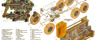
The design is made in a separate cast-iron body with three vertical, through landing channels for the spools and one channel for the bypass valve. The top and bottom of the case are closed with aluminum, one-piece lids. The connecting planes of the covers and the body are sealed with gaskets and tightened with screws.
The distributor has three working lines for the flow of working fluid, located perpendicular to the stroke of switching the position of the spools; discharge line " B" - connects the cavities of the bypass valve and spools, drain line " B" - connects the holes of the spools, the bypass valve control line " G" passes through the distributor body and the holes in the spools, bypass valve 14 is connected to the pipeline. The piston of the bypass valve is equipped throttle jet 13 to create a pressure difference in the discharge channel and sub-piston cavities, which ensures its opening in the neutral position.
The spool valves block and open the working lines with throttling recesses. Control is carried out by levers located in the lower distributor cover. The levers are connected to the spools through a spherical joint 9 with plastic liners 10 and an o-ring 8 . The joint is covered from the outside with a rubber boot 6 . Three spools allow you to simultaneously control three working hydraulic drive units.
Principle of operation
Each spool, depending on the specified position, operates in four modes:
- “ Neutral ” is the average between the uppermost “lifting” and the lower “lowering” position. The bypass valve is open and discharges the working fluid into the drain. The spool valves block all channels, thereby fixing the previously specified position of the hydraulic drive elements.
- “ Rise ” is the first upper position after “neutral”. The bypass valve closes the drain cavity. The spool passes oil from the discharge channel into the cylinder lift line.
- “ Forced lowering ” - the lower position before the extreme “floating” one. The bypass valve closes the drain cavity. The spool passes oil from the discharge channel into the return line of the hydraulic cylinder.
- “ Floating ” is the lowest position of the lever. The bypass valve is open and discharges the working fluid coming from the pump into the drain. In this position, the working fluid flows freely in both directions from both cavities of the hydraulic cylinder. The hydraulic cylinder is in a free position and reacts to external conditions and the machine’s own gravity. Thus, this allows the working bodies of the aggregating machine to follow the terrain when cultivating the soil and maintain stability of the cultivation depth.
Operation of the spool lock.
The spools are equipped with a spring-valve mechanism that automatically returns to the neutral position 3 and ball retainers that hold it in the selected position. The automatic return ball valve is activated when the pressure in the system exceeds 12.5-13.5 MPa. Excess pressure occurs when the hydraulic cylinder reaches its extreme position in the corresponding lifting and forced lowering position, as well as when the system is overloaded.
The hydraulic distribution unit is equipped with an emergency pressure relief device 20 . The safety valve is adjusted to relieve pressure exceeding a value from 14.5 to 16 mPa. The adjustment is made by screw 18 , which changes the degree of compression of the ball valve spring 17 . The device operates when the mechanism—the automatic spool valve and the bypass device—fails to operate.
Presentation for the lesson hydraulic system of the MTZ-80 tractor
5 slide
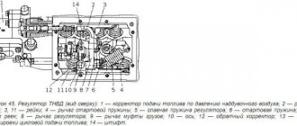
The hydraulic mounted system provides the following methods for regulating the depth of tillage with mounted machines attached to the rear linkage mechanism: high-rise - on the floating position of the distributor (with machines having support wheels); high-altitude with additional loading of the rear wheels of the tractor by part of the vertical forces acting on the mounted machine - when using GSV (with machines having support wheels); power, in which the traction resistance of the machine is maintained within certain limits and, as a result, the required depth of tillage is ensured (with machines without support wheels); positional, in which the machine is held by a hydraulic attachment system in a given position relative to the tractor frame (with machines without support wheels). When a tractor is mounted with mounted machines that have support wheels, combined control methods can also be used: power with height or position with height. With power, positional and combined control methods, the hitch mechanism with the attached machine is controlled by means of a regulator, with high-altitude with additional loading of the rear wheels - GSV and a distributor, high-altitude without additional loading - with one distributor. Each of these methods is discussed in more detail below. The distributor and hydraulic increaser of the adhesion weight are controlled through a system of rods and levers by four handles - 5, 6, 7 and 8. The leftmost lever 8 controls the spool of the right remote cylinder, the middle left lever controls the 7-spool of the left cylinder, the rightmost lever controls the 5-spool of the main cylinder, the middle the right handle 6 controls the GSV. The distributor control handles can be set to one of four positions: “neutral” - middle position, “lift” - lower, “floating” - upper, “forced lowering” - the handle position is between “neutral” and “floating”. In the first three positions, the distributor spools are held automatically by a locking device. The “forced lowering” position of the spools is not fixed, so when using this position the handle must be held by hand. The distributor provides regulation of the oil flow, and, consequently, the speed of raising or lowering the agricultural machine while holding the handle of the corresponding spool in intermediate positions between the “neutral” and “lifting” or “neutral” and “forced lowering” positions. Handle 6 GSV can be installed in one of three fixed positions and a fourth non-fixed position: “GSV off” - middle upper position; “locked” - top position; “GSV on” - middle lower position; “pressure release” is the lower position, the handle is not fixed in it, it should be held by hand. The power (position) regulator is controlled through handle 22 located to the right of the tractor driver’s seat. If the regulator is not used, the handle must be set to the lock in the “neutral” position. The support pressure in the cylinder of the linkage mechanism is adjusted by rotating the handwheel 9.
Common malfunctions of the MTZ distributor.
Attachment does not lift.
The cause may be debris that has entered the hydraulic system under the bypass valve. In this case, the bypass valve does not close - the working fluid is directed into the drain cavity. The distributor does not respond to switching the position of the spools. Eliminated: unscrew the two bolts of the bypass valve cover, dismantle the spring with the valve and remove debris.
In a situation where there is no or reduced lifting capacity of the tractor hydraulics, accompanied by overheating of the oil in the system, when a whistling sound occurs in the “lift” position of the lever, this indicates a drop in the oil level and air leakage into the system.
The attachment does not lock in the raised position.
The reason is depressurization of high-pressure hydraulic hoses and connecting fluid couplings, wear of the compression seal of the piston or rod of the power hydraulic cylinder, wear of the spool valves of the unit, the appearance of cavities on the bypass valve that prevent the valve from closing tightly.
Does not lower, does not raise attachments.
The reason is that the distributor's working lines are clogged and block the passage of oil. Oil flow control is not possible. Eliminate: disassemble and wash and clean the lines, as well as diagnose the operation of the valves.
The attachment suddenly falls down.
This indicates a sudden drop in pressure in the system; in case of rupture of oil lines and a drop in the level of working fluid, sudden airing of the system. Eliminate: replacing damaged pipelines, checking the tightness of system joints, adding oil to the required level.
The automatic transition to the neutral position does not work when the hydraulic cylinder is fully raised or lowered.
The reason is a malfunction of the ball valve for “automatic release of the spool position lock.” Eliminate; disassemble and replace worn parts of the valve and retainer.
Diagnostics
The distributor is checked after checking the performance of the six-wheel hydraulic pump of the system at rated engine speed, setting the amount of working fluid dispensed in liters per minute of operation. The KI 5473 device is connected to the working terminals of the unit instead of the hydraulic cylinder. Turn the assembly lever to the “lift” position. If the value drops by more than 5 liters/min, the distributor is removed for repairs.
Connecting the hydraulic distributor
On MTZ 82 (80) the unit is located on the front wall inside the cabin under the instrument control panel. The control levers are connected to the spools through an axle and rods with articulated joints are located on the right side of the panel. The design of the distributor allows, when moving the unit to another location or installing it on other tractor models, modifying the arrangement of the levers by reinstalling the cover with the outlets for the levers on the other side of the distributor body. For convenient connection to the hydraulic system and hydraulic equipment, the outer sections of the unit have front and redundant side lifting and lowering outlets. In addition, simultaneous connection to two spool outputs allows you to control two hydraulic cylinders simultaneously. Pipelines are connected to structurally convenient holes, the rest are closed with plugs.
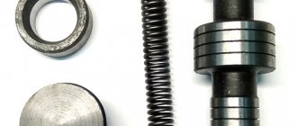
Threaded holes marked with the letter “ P ” connect pipelines intended for the lifting cavity of the hydraulic cylinder, other holes connect pipelines connecting the lowering cavity.
For a hermetically sealed connection of pipelines, the fittings are sealed with copper washers and rubber rings - seals. As a standard, one distributor spool is connected to the hydraulic power cylinder of the rear linkage of the tractor, and two spools are used to hydraulically drive remote hydraulic equipment.
If there are not enough three distributor sections for hydraulic drive and equipment control, an additional distributor is installed on the tractor. There are two connection methods: serial connection and parallel.
In the first case, the second hydraulic distributor is powered from one of the sections of the main distributor by connecting the lift output to the discharge channel of the second distributor. The output of the return flow of the working fluid used by the spool of the main unit for powering additional. distributor, close with a plug. The drain cavity of the second distributor is also connected to the hydraulic tank of the system. The distributor is activated by fixing the connected spool in the “lift” position. Thus, five working controlled flows are obtained to drive hydraulic equipment. The disadvantage is the loss of one working section and the dependence of the performance of the second distributor on the technical condition of the first unit.
A parallel connection is made by installing a hydraulic three-way tee valve on the high-pressure line coming from the pump. The valve divides the total flow of working fluid into two streams to connect two units and allows you to switch the oil flow. When switching work from one distributor to another, the oil flow is switched accordingly using a tap. The drain pipes coming from the distributors are connected with a tee. If the tractor uses a power regulator, one distributor is connected to the regulator. The second channel for controlling the bypass valve of the additional distributor is plugged. Thus, the system receives six working threads, three of which work with the power regulator. The disadvantage of this connection is the impossibility of simultaneous operation of sections on different distributors without switching the tap.
Depending on the location of the hydraulic equipment, the additional distributor is placed on the rear wall of the cabin or on the right front wall, instead of the lower viewing window. The unit is taken outside the cabin, the levers are brought inside.
It is also worth noting that this type of distributor and its modifications can be used to complete the hydraulic systems of the YuMZ-6, DT-75, T-40, T-150 tractors and their modifications.
On newer modifications of MTZ 82 (80), analogues of the above mentioned brand of monoblock unit P80-3/4-222 with power regulation and P80-3/1-222 without regulation are installed.
Other brands and designs of distributors are selected when completing additional hydraulic systems of the tractor, taking into account the type of work performed, the purpose and number of hydraulic drive units of the attached equipment. So, when using hydraulic equipment with a large number of hydraulic units, multi-section distributors are used. The spool control design uses joystick levers that allow you to simultaneously control two distributor spools, which increases the productivity and ergonomics of the driver’s workplace.
MTZ-80 “Belarus” belongs to the famous 800 series of universal row-crop wheeled tractors produced by the Minsk Tractor Plant from 1974 to the present. The 1.4 traction class tractor is a powerful and multifunctional machine that is widely used on farms, construction sites and in private business. As in the case of other components, the hydraulic circuit of the MTZ 82 is quite simple and, if necessary, can be repaired with your own hands.
Design and principle of the hydraulic system
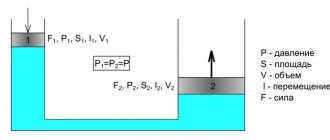
The advantages of a tractor over other equipment are well known: versatility, the ability to work with different attachments and trailers. It is the hydraulic system that makes it possible to aggregate, that is, combine the tractor with mounted and semi-mounted working equipment, various trailers and semi-trailers equipped with hydraulic mechanisms. Due to oil pressure - the working fluid of the system - manipulation of all attachments is ensured: bulldozer blades, buckets, plows and harrows, organs for planting and harvesting. The basis of the hydraulic system is a hydraulic pump and a distributor.
The pump creates the necessary pressure in the system, which makes it possible to control additional equipment and trailers. To avoid overload, it operates only at low engine speeds. The pump is located on the body of the hydraulic units, secured with studs, and centering is ensured by a special glass. The drive is connected to the intermediate gear of the power take-off shaft (PTO).
Principle of operation:
- Due to the rotation of the gears, the pump creates a vacuum in the suction zone.
- The rarefied air is discharged into the discharge hole located between the gear teeth and the pump housing.
- The required pressure is created due to the difference in the diameters of the discharge and suction holes.
The distributor performs the following functions:
- Directs oil from the hydraulic pump to the consumer (equipment or trailer).
- Ensures that the system switches to idle mode by redirecting oil to the tank.
- Limits pressure, thereby protecting the hydraulic system from overload.
The safety valve is activated when the pressure in the MTZ 82 hydraulic system increases to 135 kgf/cm².
Operating modes of the hydraulic distributor:
- Neutral (system unloading due to the bypass valve).
- Lifting - the safety valve opens, the spool spring is pressed out and oil from the tank enters the lower part of the cylinders. As a result, the attachment moves to the up position.
- Forced Lowering - The valve closes, preventing oil from entering the cylinder and causing the equipment to lower.
- Floating - the working element lowers under the influence of its own weight.
The MTZ 82 hydraulic tank is a cast iron body with one top and two side covers. A pump with a drive is attached to the lower part. The tank volume is 6 liters and is refilled with universal seasonal oils. The oil level is checked by an oil gauge using three marks: O - minimum permissible level, P - upper level, C - upper level for working with dump trailers and haystack throwers.
Hydraulic mounted system Belarus MTZ-82.1
_____________________________________________________________________________
_____________________________________________________________________________
____________________________________________________________________________________________
The Belarus MTZ-82.1, 80.1, 82.2 mounted hydraulic system ensures the operation of the rear linkage and hydraulic working parts of aggregated agricultural machines. It makes it possible to use power, positional and height methods to regulate the depth of travel of the working bodies of agricultural machines and implements. The hydraulic linkage system consists of an oil tank 2 with a filter, a pump 8, a distributor 1, a power regulator 6, a main cylinder 5, a rear linkage mechanism 4, quick-connect couplings 7, breakaway couplings and remote cylinders. The handles for controlling the distributor outputs and controlling the rear linkage (power regulator) Belarus MTZ-82-1, 80-1 are presented below. GNS units are located in different places of the tractor and are connected to each other by metal pipelines and hoses. Tractors are provided with three pairs of independent outlets: two pairs of side outlets and one pair of rear outlets, ending with quick-connect couplings and intended for connecting external cylinders. Upon request, an oil drain line 3 can be installed for operation with hydraulic motors, ending with a quick-connect coupling. Fig.94. Mounted system Belarus MTZ-82-1, 80-1, 82-2 1 – distributor; 2 – oil tank; 3 – drainage oil line; 4 – rear linkage; 5 – cylinder; 6 – power regulator; 7 – quick-connect coupling; 8 – pump. In the Belarus MTZ-82.1, 80.1 mounted system, the safety valve, retarding valve and filter valve have the following purposes: - the safety valve installed in the distributor is designed to protect the system from overloads by limiting the pressure in the range from 18 to 20 MPa (when the pressure increases above indicated, the oil flow is drained into the tank through the safety valve); — a retarding valve, installed directly in the cylinder, is designed to reduce the speed of lowering the attachment to avoid damage to the working parts on the ground; — the filter valve installed in the filter housing is designed to limit the drain pressure in the range from 0.3 to 0.4 MPa (if the filter element is clogged, the oil flow through the filter valve, bypassing the filter, is drained into the tank); Fig.95. Schematic hydraulic diagram of the mounted system with the RS-213 distributor installed 1 – tank; 2 – pump; 3 – retarding valve; 4 – priority valve; 5 – check valve; 6 – power (position) regulator; 7 – sleeve; 8 – spool; 9 – hydraulic distributor RS-213; 10 – spool; 11 – check valve; 12 – bypass valve; 13 – safety valve; 14 – hydraulic system filter; 15 – filter valve; 16 - cylinder. Fig.96. Schematic hydraulic diagram with hydraulic distributor P80-3/4-222 installed 1 – tank; 2 – pump; 3 – check valve; 4 – sleeve; 5 – spool; 6 – spool auto-return valve; 7 – overflow valve; 8 – safety valve; 9 – distributor R80-3/4-222-3G; 10 – spool; 11 – power (position) regulator; 12 – priority valve; 13 – hydraulic system filter; 14 – filter valve; 15 – cylinder; 16 – retarding valve. Adjusting the control of the power (position) regulator Adjust the regulator control rod as follows: Using nuts 2, adjust the length of the regulator control rod 1 so that when lever 3 is moved to the rearmost position along the tractor, a gap is formed between the rubber roller 5 and the edge of sector 4 within 18-24 mm. Fig.97. Adjusting the control rod of the power regulator 1 – rod; 2 – nuts; 3 – lever; 4 – sector; 5 – rubber roller Adjusting the force sensor Adjust the force sensor as follows: — set switch 1 to the middle position; — remove the central link 11 of the attachment, install the pin 12 of the central link on the upper hole of the earring 10; — using an additional lever 9, turn the shackle around finger 14 in the direction of arrow “A” until the springs 16 are fully compressed. After removing the load from the lever, the shackle should return to its original position, and the stroke of the sensor, measured by the movement of the power rod 6, should be not less than 11 mm; — after making sure that the sensor is in good condition, unscrew the castle nut 13, tighten it until the sensor springs begin to tighten, then further tighten until the slots in the nut coincide with the hole for the cotter pin and tighten. Adjusting the position rod Adjust the position rod as follows: — set switch 1 to the middle position; — lift the attachment to its highest position; — adjust the length of rod 5 so that switch 1 with its protrusion fits freely into the groove of position lever 2, then shorten rod 5 by 1 turn of adjusting nuts 8; Fig.98. Adjusting the control of the power regulator 1 – switch; 2 – position lever; 3 – power lever; 4 – traction; 5 – position traction; 6 – power traction; 7, 8 – adjusting nuts; 9 – lever; 10 – earring; 11 – central thrust; 12, 14 – finger; 13 – castle nut; 15 – spring; 16 – springs. Adjusting the power draft Adjust the power draft after adjusting the power sensor: — set switch 1 to the middle position; — using an additional lever, create a force that ensures the earring rotates to its extreme position (in the direction of arrow “A”); — holding the lever in the depressed position (in the direction of arrow “A”), check whether the protrusion of switch 1 can be inserted into the groove of power lever 3. If this fails, adjust the length of rod 6 so that switch 1 with its protrusion fits freely into the groove of power lever 3; — shorten the rod 6 by 1 turn of the adjusting nuts 7. When an agricultural implement is mounted on a Belarus MTZ-82-1, 80-1 tractor, the use of a special additional lever for adjusting the power rod is not required. In this case, it is enough to lift the implement above the surface of the platform on which the tractor stands, and the mass of the implement will create the necessary tensile force on the force sensor through the central link. It should be remembered that in this case the central link must be installed on the upper hole of the hitch link. Raise the implement only until it leaves the ground. Adjusting the power regulator control rod on Belarus MTZ-82.1, 80.1 tractors with an awning frame or an awning base based on a small cabin: Using nuts 7, adjust the length of the regulator control rod 8 so that when moving handle 3 to the rearmost position along the tractor between handle 3 and the edge of the slot in sector 1, a gap “G” equal to 11+5 mm has formed. Fig.99. Adjusting the control rod of the power regulator on tractors with an awning frame or an awning base based on a small cabin 1 – sector; 2 – gear sector; 3 – handle; 4 – spring; 5 – adjusting bolt; 6 – bolt; 7 – nuts; 8 – traction. For clear fixation of handle 3 in all positions on gear sector 2, as well as free installation on and removal from bolt 6, adjust the tension of spring 4 using bolt 5.
The movement of handle 3 from bolt 6 along arrow “L” should be easy and free; after the movement stops, handle 3 should spontaneously return to bolt 6.
_____________________________________________________________________________
__________________________________________________________________________
Service and adjustments MTZ-82
- Controls and instruments
- Working with agricultural machinery
- Maintenance of diesel engine D-243
- Clutch adjustments
- Steering
- Tractor brakes Belarus
- PTO power take-off shaft
- Front axle
- Front drive axle repair
- Hydraulic system and rear linkage
- Electrical equipment
- Maintenance
__________________________________________________________________________
Operation and service MTZ-82.1, 80.1, 80.2, 82.2
- Controls and instruments
- Gearbox and PTO control
- Rear linkage control
- Cabin elements
- Electrical components
- Clutch
- Transmission
- Gearbox and creeper control
- Reverse gearbox
- Rear axle of Belarus tractor
- Rear axle differential lock
- Rear power take-off shaft
- Tractor brakes Belarus
- Pneumatic system
- FDA with bevel wheel reducers
- FDA with planetary helical wheel reducers
- FDA drive
- Chassis system
- Hydrostatic steering
- Power steering
- Hydraulic linkage system
- Rear linkage adjustments
- Cabin Belarus
- Maintenance
- Engine Maintenance
- Transmission Maintenance
- Front drive maintenance service
- Hydraulic and steering maintenance
- Front Axle Maintenance
- Maintenance of the pneumatic system and brakes
Repair of MTZ-80
- Cylinder head repair
- Repair of piston group D-240
- Repair of fuel equipment
- Starting motor repair
- Steering repair
- Front axle repair
- Clutch and reduction gear repair
- Transmission repair
- Rear axle repair
- PTO repair
- Rear linkage hydraulic system repair
- Electrical equipment repair
Maintenance and operation of MTZ-1221
- Controls and instruments
- Transmission
- Clutch
- D-260 engine maintenance
- Rear axle
- Service brakes
- Pneumatic equipment
- PTO
- Front drive axle
- Mounted hydraulic system
- Electronic rear linkage control
- Rear linkage
- Steering
Maintenance and operation of MTZ-320
- Controls and instruments
- Diesel engine
- Clutch and gearbox
- Rear axle
- Brakes
- Rear power take-off shaft
- Front drive axle
- Steering
- Hitch and hitch
- Hydraulic system
- Electrical equipment
- Aggregation
Operation and service of tractors
- Block crankcase and crank mechanism
- Gas distribution mechanism
- Diesel engine power supply system
- Tractor engine control system
- Tractor engine cooling system
- Diesel starting system
- Tractor power transmissions
- Tractor transmission T-150, T-150K
- Drive axles of wheeled and tracked tractors
- Tractor chassis and control
- Chassis and steering of wheeled tractors
Hydraulic system diagram
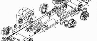
The general structure of the system includes:
- gear pump for hydraulics NSh-32-2;
- distributor Р75-33-Р;
- main cylinders Ts100 and two remote cylinders Ts75;
- power regulator providing four operating modes;
- hydraulic adhesion weight increaser (GWI), which reduces wheel slip and facilitates the operation of equipment;
- a hydraulic accumulator that serves to maintain pressure and replenish possible oil leaks;
- locking devices;
- MTZ hydraulic breakaway coupling (2 pcs);
- hydraulic tank (oil reservoir);
- oil filter;
- fastening fittings.
The pump is connected to the tank, distributor and power regulator. The suction pipe goes to the tank, and the oil discharge pipes go to the distributor and regulator. The oil flow is directed by a distributor either to the tank or to the fuel pump and then through the regulator and power cylinder it is supplied to the hydraulic drive of the trailer or attachment. As a result, the working body (blade, bucket, mower) moves in accordance with the operator’s commands.
Design, diagram and components of the MTZ 80 hydraulic system
The hydraulic system is designed to provide hydraulic drive to the tractor's mounted system, as well as to provide hydraulic drive to the external power hydraulic elements of mounted and trailed machines working with the tractor. The hydraulic mounted system of universal row-crop tractors MTZ 80(82) is additionally equipped with units that automatically regulate the depth of tillage and increase the grip weight of the tractor drive wheels when working with soil-cultivating devices.
Possible faults
Proper operation of the system is ensured by the use of suitable parts and consumables, as well as timely maintenance. Maintenance comes down to regular oil changes, as well as checking the condition of parts, linings and oil lines.
The oil is changed once a season or after every 2000 operating hours. First start the engine until the oil warms up to 30° C. Then turn off the engine and drain the used oil through the drain hole in the bottom of the crankcase. The hydraulic oil filter is removed and washed in diesel fuel. The washed filter is put back in place and fresh oil is added until about. The recommended brand of hydraulic oil for MTZ 82 is M-8G2K, M-10G2K, M-10G2. At the final stage, start the engine and lower and raise the rear linkage mechanism several times to bleed the hydraulic system.
Maintenance memo:
- every 10 operating hours - check the oil level in the tank and make sure there are no leaks in the seals and connections of the system;
- every 60 m/h – clean the oil filter rotor;
- every 240 m/h – change the power steering oil;
- every 960 m/h – clean and rinse the drain filters;
- every 2000 m/h - change the oil in the power steering and wash the filters.
At the same time, the activation of the drive gear, the locking mechanism of the GSV control levers, the distributor, and power position control systems are adjusted.
The most common faults:
- wear of levers and hoses;
- incorrect adjustment;
- problems with traction;
- oil leak.
Remedies
Problem: attachments do not raise or lower.
Reason: lack of oil in the tank. Top up to the mark.
Problem: increased oil heating.
Cause: incorrect adjustment of the regulator control sector. It needs to be adjusted.
Problem: Lifting the attachment too slowly .
Cause: The hydraulic pump may be damaged, causing an oil leak. A damaged pump must be replaced.
Problem: wheel slipping when the GSV is turned on.
Reason: violation of the length of the rod of the lever controlling the main cylinder. The rod length needs to be adjusted.
Knowledge of these main faults will help you figure out if the hydraulics on the MTZ 82 do not work, what is the reason and what to do. Most problems can be fixed by yourself, but for everyone else there are forums and professional help.