Timing belt of KamAZ-740 engine
The gas distribution device is designed to admit air into the cylinders and exhaust exhaust gases.
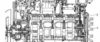
The opening and closing of the intake and exhaust valves occurs in strictly designated positions in relation to the top and bottom dead centers, which correspond to the rotation angles of the crankshaft journal. The gas distribution device of the KAMAZ engine is overhead valve (Fig. 4). The camshaft cams (1) in a certain order activate the pushers (2). The rods (4) communicate rocking movements to the rocker arms (6), which, overcoming the resistance of the springs (13, 14), open the valves. The valves close under the influence of the force of compressed springs.
Drawing. 4. Gas distribution device:
1 - camshaft; 2 - pusher; 3 — orienting pushers; 4 — rod; 5-head cover gasket; 6 — rocker arm; 7 - nut; 8 — adjusting screw; 9 — head cover fixing bolt; 10 - cracker; 11 — plate bushing; 12 — spring plate; 13 — outer spring; 14 — internal spring; 15 - valve guide; 16- washer; 17- valve; A - thermal gap
Torque is transmitted to the camshaft from the crankshaft through the drive gears of the units.
The cylinder heads of the KAMAZ engine, cast from aluminum alloy, have cavities for coolant that communicate with the block jacket. The joints of the cylinder head and liner, head and block are sealed with gaskets. A gas joint ring is pressed into the groove on the mating surface of the head, with which the head is directly placed on the cylinder liner collar (Fig. 5). The impermeability of the seal is guaranteed by very high precision processing of the mating planes of the ring and cylinder liner and, additionally, by applying a lead coating to the plane of the ring to compensate for micro-roughness of the sealing planes. The coolant bypass passages are sealed using silicone rubber O-rings installed with shanks in the bores of the cylinder head. The head space, engine oil drain hole and rod passage are sealed with a molded cylinder head gasket.
Drawing. 5. Joints of the cylinder head and liner, head and cylinder block:
1 - thrust ring; 2 - cylinder head; 3 - gasket; 4-cylinder block; 5 — sealing ring of the sleeve; 6-cylinder liner
The inlet and outlet channels are located on opposite sides of the head. The supply channel contains a tangential profile for swirling air in the cylinder. Each head is fixed to the block with four bolts
The valve device is closed with an aluminum cover, under which there is a sealing gasket.
The camshaft (Fig. 6) is made of steel, the planes of the cams and bearing journals are cemented and hardened with very high frequency currents. The shaft is placed in the camber of the block on five plain bearings.
The rear support bearing is a bushing clad in bronze and pressed into a removable cast iron base. Bushings made of bimetallic tape, pressed into the transverse partitions of the block, serve as bearings for other shaft supports.
The axial movement of the camshaft of the KAMAZ engine is limited by the bearing housing (2), the ends of which rest on the gear hub (8) on one side, and on the other - the stubborn shoulder of the rear support of the shaft journal. The base of the rear support bearing is fixed to the block with three bolts.
Calculation of axial and disaxial crankshafts Calculate the values of displacement, speed and acceleration of the piston of axial and disaxial crankshafts, using approximate expressions to determine them. Carry out the calculation every 30 degrees of crankshaft rotation. Draw graphs based on the calculation results. Compare the results. For ax.
Jets and hydraulic accumulators The second main task of any automatic transmission control system, after determining the gear shift moments, is the task of ensuring the required quality of the shifts themselves. In other words, the automatic transmission control system must control shifts in such a way as to prevent the clutch from sliding for too long.
Thermal technical tests of ship units and mechanisms The main purpose of the tests is to obtain technical and operational characteristics and equipment in the power plant, determine the optimal mode of their operation, identify design and operational deficiencies, find ways to increase the speed and increase the efficiency of the vessel. Before the vessel is put into operation, the SEU.
CAR REPAIR
Design and operation of gas distribution mechanisms On modern automobile engines, gas distribution mechanisms with an overhead (in the block head) valve arrangement have become predominant. These mechanisms make it possible to improve cylinder filling and increase the compression ratio in the internal combustion engine. Using the example of the KamAZ-740 engine, let's look at the general design of the gas distribution mechanism. The camshaft is located in the camber of the cylinder block and is driven into rotation by the crankshaft gear through a gear pressed onto the tail of the shaft with a key. The shaft supports are steel bushings filled with anti-friction alloy; The bushings are installed in the cylinder block and in the rear support housing. Above the camshaft on the cylinder block, cast iron pushrod guides are bolted. The pusher plates rest on the shaft cams, and steel rods are inserted into the pushers. The rocker arms of the intake and exhaust valves are located on a stand secured to the cylinder head with studs. The valves are installed in metal-ceramic guide bushings pressed into the cylinder heads. In the closed position, the valves are held by two springs of different sizes: internal and external. The springs are secured to the valves using a washer, a plate, a bushing and two conical crackers. There are oil seals on the intake valve stems. When the shaft rotates, its cams, in accordance with the sequence of operation of the cylinders, “run” onto the pushers and move them upward. The pushers transmit force through rods 4 and adjusting screws 5 with locknuts to the arms of the rocker arms 6 and rotate them around the axis of the rocker arm. The long arms of the rocker arms with their tip-toes press on the ends of the valve stems, which open, while the springs are compressed. The process of gas exchange occurs. As the camshaft cams move from under the pushrods, the springs close the valves and return the drive mechanism group parts to their original position. When the engine is running, the valves rotate due to the spring lock design and vibration. This ensures even wear of the valves and their seats. Therefore, in some designs of the MGR (ZIL-130 engine), a ball mechanism for forced rotation of the valves is used. The design of the MGR with a camshaft on the cylinder head and a toothed belt drive is shown in the figure. For engines with prechamber ignition, in addition to the conventional intake valve of the main combustion chamber, an additional valve is installed in the prechamber. Both valves are actuated by one rocker arm. When entering the main combustion chamber (into the cylinder), a combustible mixture enters through the valve, the composition of which is determined by the operating mode of the internal combustion engine, and a mixture of an enriched composition enters the prechamber through an additional valve. After ignition of the enriched mixture of spark plugs, a torch of flame or active products of incomplete combustion is ejected from the prechamber, which enters the main combustion chamber through channels in the cylinder head, reliably and quickly ignites the working mixture in it. After studying the general structure of the MGR, it is necessary to compare different designs of mechanisms, determine their common and individual distinctive features, and show the operation of the mechanism on a full-scale dynamic section of the internal combustion engine. Camshafts. These parts are made in the form of a cylindrical rod with support journals, between which the cams for driving the intake and exhaust valves are located. The most widespread are two types of cams: unstressed and with a convex profile. The cams are machined to a cone, which ensures rotation and uniform wear of the surfaces of the pushers during operation (3M3-53 engine). To supply engine oil in the cam support journals along the axis of the camshafts, some designs make holes by drilling. On the camshafts of carburetor, V-shaped and some in-line internal combustion engines there is an eccentric cam for driving the fuel pump, a wheel with a screw tooth for driving the lubrication pump and the distributor-distributor. Typically, the front end of the shaft (on the KamAZ-740 engine - the rear end) is processed for the installation of a gear wheel, a toothed sprocket or a toothed pulley for the shaft drive. The shaft supports are bearings made in the form of metal-ceramic bushings (YaMZ-238 engine), steel bushings with anti-friction filling (KAMAZ-740 engine), rolled from bimetallic and steel-babbit tape (3M3-53 engine).
The camshafts are held against axial displacement by stops bearings (flanges) mounted on the block or cylinder head between the ends of the front support journal and the hub of the gear wheel or distribution sprocket. The camshafts of the internal combustion engines of trucks are made from steel 20, 40 and others using the method of volumetric stamping, and the camshafts of passenger car engines are made from cast iron. To strengthen, the working surfaces of the bearing journals and cams of steel shafts are hardened with high-frequency heating, and cast iron shafts are subjected to bleaching. Lever-roller tappets have a roller with a needle bearing mounted on an axle; a bronze bushing pressed into the mounting hole and a lubrication channel in the lever. The pushers are made from cast iron and carbon steel, the friction surfaces are hardened, and the working mountaineers overlay them with bleached cast iron. Valves. Typically, one intake and one exhaust valve are provided for one cylinder; some internal combustion engines (for example, YaMZ-8401) have two valves to ensure good gas exchange. The main elements of the valves are a stem with a locking groove and a head with a machined sealing edge-chamfer, which fits tightly to the sealing surface of the valve seat. The angle of inclination of the chamfer is 30-40°. To ensure high-quality filling of the cylinders, the intake valve heads usually have a larger diameter. The exhaust valves of some engines have additional cooling; For this purpose, a cavity is provided in the valve stem and head, partially filled with sodium and closed at the bottom with a plug. Valves are made of heat-resistant steel. Sometimes exhaust valves; They are performed in combination (the head is made of steel with increased heat and corrosion resistance and is welded to the valve stem (YAM3-238 engines)). The head chamfer is overlaid with particularly hard and heat-resistant materials, for example, chromium-nickel alloy (3M3-53 engine). To increase wear resistance, the valve stems are chrome plated, and the ends of the stems are hardened or caps with high hardness of the end surfaces are installed on them. Plug-in seats are made in the form of rings with sealing chamfers made of steel or cast iron and are pressed into the head, which improves its maintainability. Order motor oil wholesale gsmmasla.ru, buy M-10G2 from the manufacturer RosNeft with delivery. Basic assembly and adjustment operations. To ensure valve timing, the installation of gears (sprockets) of the shafts must be done according to the marks marked on the ends of the teeth, aligning them with the gears (sprockets) of the crankshaft. After installing the drive chain (toothed belt), their tension should be adjusted. The tightening of nuts or bolts for fastening gear wheels and drive sprockets, guide pushers, rocker arm axle stands, and adjusting screw nuts is carried out according to the value of the controlled torque. When installing and removing valve springs, special tools are used. To avoid scoring in the guide bushings during MGR operation, before assembling, it is recommended to lubricate the valve stems with a mixture of graphite powder and engine oil (in a ratio of 7:3). Upon completion of assembly of the mechanism, it is necessary to adjust the thermal clearances in the valves. The gap is set and checked (Fig. between the front part of the rocker arm 3 and the end of the valve stem 5, usually on a cold engine. The gap width for most internal combustion engines for intake valves is 0.15 -0.25 mm, and for exhaust valves 0.2 - 0.35 mm,
Design and operation of the Kamaz 740 engine timing system
CRANK AND GAS DISTRIBUTION MECHANISMS OF KAMAZ-740 ENGINE - PART 2
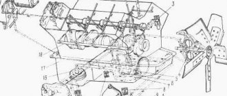
4. Gas distribution mechanism.
The engine is equipped with an overhead valve timing mechanism with a lower camshaft. Its device is shown in Fig. 1.20.
Rice. 1.20. Gas distribution mechanism: 1 - camshaft; 2 - pusher; 3 — pusher guides; 4 - rod; 5 - adjusting screw; 6 — valve rocker arm; 7 - lock nut; 8 — bushing; 9 - plate; 10 — internal spring; 11 — outer spring; 12 - washer; 13 — inlet valve; 14 — exhaust valve; 15 - key; 16 - bearing housing with flange; 17 — timing gear; 18 - cracker; 19 — cuffs