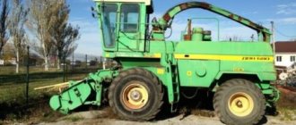
Don-1500 [up]
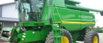
Don-1500 is a combine harvester, known since Soviet times (“1500” is the width of the threshing drum).
Today it is still in demand among Russian grain harvesting equipment. Released. There are various modifications of the combine. For the non-chernozem zone - DON-1500, DON-1500A, DON-1500B, Don-1500N; rice harvester, caterpillar - Don-1500R. Since 1986, the combine has been in mass production. And very soon it became one of the most popular grain harvesting machines in the CIS. The Don-1500 was replaced in 2006 by a series of Acros 530 and Vector 410 combines.
The DON-1500 combine harvesters were equipped with D-260 and YaMZ-238 diesel engines. The SMD-31A engine was initially installed.
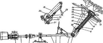
Not available:
| № | Part code | Name | Part Information |
| RSM-10-09-09-260B | casing | Quantity per Don 1500B (header working width 6 m) 2) Don 1500B (header working width 7 m) 3) Don 1500B (header working width 8.6 m) 1 | Not available |
| 54-52339 | screw | Quantity per Don 1500B (header working width 6 m) 2) Don 1500B (header working width 7 m) 3) Don 1500B (header working width 8.6 m) 1 | Not available |
| RSM-10-09-01-504 | Ribbon | Quantity per Don 1500B (header working width 6 m) 2) Don 1500B (header working width 7 m) 3) Don 1500B (header working width 8.6 m) 1 | Not available |
| М8-6gх35-48-019 | Bolt | Quantity per Don 1500B (header working width 6 m) 2) Don 1500B (header working width 7 m) 3) Don 1500B (header working width 8.6 m) 1 | Not available |
| RSM-10-09-09-350B | Sleeve | Quantity per Don 1500B (header working width 6 m) 2) Don 1500B (header working width 7 m) 3) Don 1500B (header working width 8.6 m) 1 | Not available |
| RSM-10-09-06-020A | Sleeve | Quantity per Don 1500B (header working width 6 m) 2) Don 1500B (header working width 7 m) 3) Don 1500B (header working width 8.6 m) 1 | Not available |
| 011-015-25-2-2 | Ring sealing | Quantity per Don 1500B (header working width 6 m) 2) Don 1500B (header working width 7 m) 3) Don 1500B (header working width 8.6 m) 1 | Not available |
| N-036-67-100-10 | Outer coupling half | Quantity per Don 1500B (header working width 6 m) 2) Don 1500B (header working width 7 m) 3) Don 1500B (header working width 8.6 m) 1 | Not available |
| RSM-10-09-01-480 | Pipeline | Quantity per Don 1500B (header working width 6 m) 2) Don 1500B (header working width 7 m) 3) Don 1500B (header working width 8.6 m) 1 | Not available |
| RSM-10-09-01-670B | Collector | Quantity per Don 1500B (header working width 6 m) 2) Don 1500B (header working width 7 m) 3) Don 1500B (header working width 8.6 m) 1 | Not available |
| RSM-8-09-01-200 | Collector | Not available | |
| RSM-10-09-01-006 | Sleeve | Quantity per Don 1500B (header working width 6 m) 2) Don 1500B (header working width 7 m) 3) Don 1500B (header working width 8.6 m) 1 | Not available |
| RSM-10-09-01-680B | Pipeline | Quantity per Don 1500B (header working width 6 m) 2) Don 1500B (header working width 7 m) 3) Don 1500B (header working width 8.6 m) 1 | Not available |
| RSM-10-09-01-647 | Screw-in fitting | Quantity per Don 1500B (header working width 6 m) 2) Don 1500B (header working width 7 m) 3) Don 1500B (header working width 8.6 m) 1 | Not available |
| RSM-10-09-01-790B | Pipeline | Quantity per Don 1500B (header working width 6 m) 2) Don 1500B (header working width 7 m) 3) Don 1500B (header working width 8.6 m) 1 | Not available |
| RSM-10-12-07-080A | Traction | Quantity per Don 1500B (header working width 6 m) 2) Don 1500B (header working width 7 m) 3) Don 1500B (header working width 8.6 m) 1 | Not available |
| RK-00-000 | Accumulator distributor | Quantity per Don 1500B (header working width 6 m) 2) Don 1500B (header working width 7 m) 3) Don 1500B (header working width 8.6 m) 1 | Not available |
| RSM-10-09-01-690A | Pipeline | Quantity per Don 1500B (header working width 6 m) 2) Don 1500B (header working width 7 m) 3) Don 1500B (header working width 8.6 m) 1 | Not available |
| RSM-10-09-01-630A | Pipeline | Quantity per Don 1500B (header working width 6 m) 2) Don 1500B (header working width 7 m) 3) Don 1500B (header working width 8.6 m) 1 | Not available |
| 54-60506 | Bolt | Quantity per Don 1500B (header working width 6 m) 2) Don 1500B (header working width 7 m) 3) Don 1500B (header working width 8.6 m) 1 | Not available |
| 016-020-25-2-2 | Sealing ring | Quantity per Don 1500B (header working width 6 m) 2) Don 1500B (reaper working width 7 m) 3) Don 1500B (header working width 8.6 m) 3 | Not available |
| RSM-10-09-01-740A | Pipeline | Quantity per Don 1500B (header working width 6 m) 2) Don 1500B (header working width 7 m) 3) Don 1500B (header working width 8.6 m) 1 | Not available |
| RSM-10-09-01-700B | Pipeline | Quantity per Don 1500B (header working width 6 m) 2) Don 1500B (header working width 7 m) 3) Don 1500B (header working width 8.6 m) 1 | Not available |
| RSM-8-09-01-210B | Pipeline | Not available | |
| KDN-00-000 | Adjustable throttling valve | Quantity per Don 1500B (header working width 6 m) 2) Don 1500B (header working width 7 m) 3) Don 1500B (header working width 8.6 m) 1 | Not available |
| N-036-84-030 | High pressure hose P-12 reinforced | Quantity per Don 1500B (header working width 6 m) 2) Don 1500B (reaper working width 7 m) 3) Don 1500B (header working width 8.6 m) 2 | Not available |
| RSM-10-09-02-100B | Hydraulic cylinder | Quantity per Don 1500B (header working width 6 m) 2) Don 1500B (reaper working width 7 m) 3) Don 1500B (header working width 8.6 m) 2 | Not available |
| RSM-10-09-02-180A | Pipeline | Quantity per Don 1500B (header working width 6 m) 2) Don 1500B (header working width 7 m) 3) Don 1500B (header working width 8.6 m) 1 | Not available |
| RSM-8-09-02-030 | Pipeline | Not available | |
| 54-51781 | Washer | Quantity per Don 1500B (header working width 6 m) 2) Don 1500B (reaper working width 7 m) 3) Don 1500B (header working width 8.6 m) 3 | Not available |
| RSM-10-09-01-007A | Pad | Quantity per Don 1500B (header working width 6 m) 2) Don 1500B (reaper working width 7 m) 3) Don 1500B (header working width 8.6 m) 4 | Not available |
| RSM-10-09-04-301B | Rotary square | Quantity per Don 1500B (header working width 6 m) 2) Don 1500B (reaper working width 7 m) 3) Don 1500B (header working width 8.6 m) 2 | Not available |
| RSM-10-09-01-639 | Special bolt | Quantity per Don 1500B (header working width 6 m) 2) Don 1500B (reaper working width 7 m) 3) Don 1500B (header working width 8.6 m) 2 | Not available |
| N-036-85-660 | High pressure hose P-16 reinforced | Quantity per Don 1500B (header working width 6 m) 2) Don 1500B (header working width 7 m) 3) Don 1500B (header working width 8.6 m) 1 | Not available |
| RSM-10-09-05-820A | Pipeline | Quantity per Don 1500B (header working width 6 m) 2) Don 1500B (header working width 7 m) 3) Don 1500B (header working width 8.6 m) 1 | Not available |
| GA-93000-02 | Hydraulic cylinder | Quantity per Don 1500B (header working width 6 m) 2) Don 1500B (header working width 7 m) 3) Don 1500B (header working width 8.6 m) 1 | Not available |
| N-036-87-01-140 | High pressure hose P-8 reinforced | Quantity per Don 1500B (header working width 6 m) 2) Don 1500B (reaper working width 7 m) 3) Don 1500B (header working width 8.6 m) 2 | Not available |
| RSM-10-09-13-803B | Pipeline | Quantity per Don 1500B (header working width 6 m) 2) Don 1500B (header working width 7 m) 3) Don 1500B (header working width 8.6 m) 1 | Not available |
| RSM-10-09-06-040 | Sleeve | Quantity per Don 1500B (header working width 6 m) 2) Don 1500B (header working width 7 m) 3) Don 1500B (header working width 8.6 m) 1 | Not available |
| RSM-10-09-13-806A | A tube | Quantity per Don 1500B (header working width 6 m) 2) Don 1500B (header working width 7 m) 3) Don 1500B (header working width 8.6 m) 1 | Not available |
| RSM-10-09-01-011 | Hose | Quantity per Don 1500B (header working width 6 m) 2) Don 1500B (header working width 7 m) 3) Don 1500B (header working width 8.6 m) 1 | Not available |
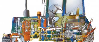
Main hydraulic system [top]
The system controls many mechanisms and assemblies of the combine: rotation and drive of the unloading device, control of the header and reel, opening of the stacker, control of the hopper and drum vibrators. It uses sectional distributors with electrohydraulic and muscular control of the spools of the working bodies. When the relay of a particular hydraulic valve is energized, it shuts off the flow, creating pressure in the system. At the same time, it acts on the spool, thereby opening the line of the selected consumer.
What is the purpose of the main hydraulic system (OHS)?
The function of the OGS is to control all the working parts of the Don-1500 and Don-1200 combines that participate in their technological process.
The main hydraulic system is designed to perform twelve operations:
- raising and lowering the header,
- horizontal and vertical movement of the reel,
- scrolling the feeder chamber, driving the unloading augers,
- turning the unloading inclined auger,
- turning the thresher drive on and off,
- turning on vibrators to activate the unloading of grain from the bunker and control the stacker,
- changes in the rotation speed of the reel and threshing drum.
The speed of movement of a combine with a mechanical drive of the chassis is changed within the range established in the box by a variator, also controlled using the OGS. If the combine is equipped with a chopper with a trailed trolley, the OGS can automatically couple the trolley to the combine and tip it over. The system is sealed and is filled with working fluid through a fine filter using a supercharger.
It must be remembered that there are four types of working fluid flows in the system - an integral component of any hydraulic system. It is the working fluids that protect the working elements from wear. Thanks to them, the equipment operates normally under conditions of different temperatures, loads and humidity.
Adjusting the combine hydraulic circuit and troubleshooting
The hydraulic system of the Don-1500 combine harvester consists of three independent hydraulic systems: the main hydraulic system, the volumetric steering system and the volumetric drive of the chassis.
The main one - performs many operations: raises (lowers) the header and reel, changes the rotation speed of the reel and threshing drum, moves the reel horizontally, turns the unloading auger to the working and transport position, turns on (off) the drive of the thresher and unloading auger, reverse scrolling (reversing) the feeder conveyor, closes the stacker and improves the unloading of wet grain from the bunker.
Given the versatility and complexity of this system, it is often difficult to determine the causes of failures and eliminate them promptly, especially in the field.
Many years of experience at the Tambov Technical Institute (organized by VIITiN) in eliminating the consequences of failures allowed us to develop methods for searching for their causes and ways to eliminate them. These methods are based on the principle of finding and eliminating the consequences of failures “from simple to complex” with the least amount of labor.
Searching for and eliminating the consequences of failures of the main hydraulic system must be carried out according to external signs of their manifestation in the sequence indicated in the table
| External manifestation of failure and possible causes | Identifying and eliminating the consequences of failures |
| All consumers of the hydraulic system do not work, there is no pressure in the system | |
| Insufficient oil level in the hydraulic system tank | Check the level using the oil indicator in the tank, refill it to the upper mark (oil M-10V2, M-8V GOST 8581-78, GOST 10541-78) |
| Oil is not supplied to the NSh-32A-3 pump (increased pump noise) | |
| The suction hose is pinched | Inspect the sleeve, eliminate pinching |
| There is no spring inside the suction arm | Check by touch for the presence of the spring. Insert the spiral spring with its ends bent inwards into the suction hose |
| Loosening the tension device of the NSh-32A-3 pump drive | Check the degree of tension and, if necessary, adjust the belt tension |
| Pump NSh-32A-3 does not rotate | Check the temperature of the pipelines before and after the safety overflow valve. If after starting the engine the pipelines do not heat up within 15 minutes, you need to check the condition of the pump drive (spline bushing and retaining rings on the pulley) |
| The safety overflow valve (PPV) 108.00.000B is not adjusted | Check the gearbox response pressure. Adjust it to a value of 1 25±5 kgf/cm2. To do this, you need to rotate the bolt in the required direction (tightening - more pressure, unscrewing - less pressure). After adjustment, tighten the locknut and seal the bolt. The valve adjustment should be made at the rated engine speed (2000 rpm) and an oil temperature of 50°. |
| The gearbox is clogged | Remove the discharge flange from the valve. If oil flows from the gearbox in a continuous stream, it means the valve is stuck. Press the valves all the way with the blunt end of the bit and release. The leak should become drop-shaped. When performing operations, the tool should not fall into the valve-seat gap. |
| The outer sealing washer (fluoroplastic) of the gearbox bushing has failed. The bushing is installed with the outer flange up | Disassemble and wash the gearbox. Visually check the sealing washer for serviceability. If there is a rupture or crumpling, or pressing in of the washer's shoulders, replace it. Install the bushing and ring correctly |
| A foreign object (piece of rubber, scale, shavings, etc.) gets under the gearbox needle. | Disassemble the gearbox safety part. Check for foreign objects. Wash the safety part with diesel fuel and, if necessary, adjust the gearbox response pressure (125±5 kgf/cm2) |
| Gearbox inoperative | Perform the above operations. If there is no positive result, replace the gearbox |
| Loss of performance of pump NSh-32A-3 | If there is no pressure when replacing the gearbox, check the pump performance with a DR-90 throttle manufactured by GOSNITI. Replace the pump if necessary |
| Increased oil heating during system operation | |
| Insufficient oil in the hydraulic tank | Check the oil level in the hydraulic tank. Refill the hydraulic tank to the upper oil indicator mark |
| Hydraulic tank filter element (635-1-06) dirty | The “filter clogged” icon should light up in the cabin. Replace the filter element. Do not drain the oil from the tank when replacing the filter. (When the oil is cold, the “filter clogged” icon may light up, but it should go out as the oil warms up) |
| Rapid heating and overheating of oil when hydraulic controls are turned off | |
| Presence of constant pressure in the system (more than 10 kgf/cm) | Measure the pressure in the main hydraulic system at the gearbox with the controls turned off |
| The rods from the hay dump sensor beam to the stacker distributor are not adjusted | Check linkage adjustment. With the accumulator valve closed, the accumulator distributor spool pusher must be fully extended (rightmost position) |
| The accumulator distributor spool is jammed | Check the movement of the pusher by first disconnecting it from the rods. If it moves without effort, you need to disassemble it, wash it with diesel fuel and look for damage. If necessary, replace the accumulator distributor |
| Mechanical distributor control rod jammed | Check the movement and ease of movement of the rods, eliminate any detected jams |
| Mechanical distributor spool not in neutral position | Check the neutral position of the spool with the control handle in neutral position. Adjust the mechanical distributor rods |
| The hydraulic valve with electromagnetic control 109.00.000 is jammed | If the pressure in the main system does not decrease to 4 kgf/cm2 with the controls turned off, replace the electrohydraulic valve 109.00.000 |
| Oil release from the breather, oil foaming in the hydraulic tank | |
| Air leak into the system | Check the condition (foaming) of the oil through the oil indicator glass of the hydraulic tank. Tighten the suction flange on the pump, fittings and clamps of the suction oil lines. Replace damaged flange O-rings, damaged hoses |
| Slow movement of working parts at rated engine speed | |
| (at n=2000 min-1 and heated oil t=50°) | |
| Low pressure in the main hydraulic system due to gearbox misadjustment | Adjust the gearbox to 125 kgf/cm2 and seal it |
| Slipping of pump drive belts NSh-32A-3 | Check the tension of the pump drive belts |
| Increased oil leaks in the NSh-32A-3 pump | Check the pressure in the system. If it is impossible to raise it at the gearbox to 125 kgf/cm2, check and replace the pump |
| Header won't lower | |
| The marks on the spindle and the throttling valve body are not aligned | Check the alignment of the marks. Combine the corresponding risk, heavier header - smaller throttle diameter, lighter - larger |
| The locking device of the mechanical distributor in the header lifting section does not drain the working fluid | Disassemble the locking device. Replace valve and bushing |
| The header lifting handle in the cab rests against the panel | Check the spool stroke when moving the control handle. The spool stroke should be ±7 mm from neutral. Adjust the spool thrust |
| Spontaneous lowering of the header (pickup) | |
| The mechanical distributor locking device in the header lift section does not provide a tight seal | Disassemble the locking device. Replace valve, bushing or rubber ring |
| Reel extension hydraulic cylinders operate asynchronously | |
| Presence of air in hydraulic cylinders | Bleed air in the hydraulic system by alternately loosening the oil line fittings on the hydraulic cylinders |
| There is no tightness of the shut-off device of the corresponding section of the mechanically controlled distributor | Disassemble the locking device, replace the O-ring |
| Internal oil leaks in hydraulic cylinders | Disassemble the right cylinder and replace the piston O-ring. After assembly, bleed the oil. |
| The reel variator hydraulic cylinder does not move the movable pulley | |
| The movable pulley is not lubricated | Lubricate the pulley |
| Reel speed does not change | |
| The spring on the driven pulley has broken | Check the function of the spring and, if possible, replace it |
| Leak along the spindle of the reel variator hydraulic cylinder | |
| Cuff tear | Replace the cuff. Lubricate it with oil before installation |
| All consumers from the mechanical distributor work normally, but from the electric hydraulic distributors they do not work | |
| The solenoid valve is not working. No voltage | Check the voltage supply and the integrity of the ground wire at the contacts of the solenoid-controlled valve. If there is no voltage, check the fuse links, the voltage on the keys and the contacts of the electrohydraulic remote control keys, the integrity of the wiring and the contacts of the connecting chips of the electric circuit of the solenoid valve |
| The solenoid valve is not working. Voltage is applied | Replace solenoid valve 109.00.000 |
| One of the consumers of the electrical distribution section does not work | |
| Voltage is supplied simultaneously to two opposite coils of the distributor section | Check the serviceability of the VD-2 diode blocks in the electrohydraulics control panel. Replace the faulty unit |
| There is no tightness of the seat and needle on the side opposite the oil supply to the hydraulic cylinder | Disassemble the valve and look at the details. Grind in the conical surfaces or replace the seat and rubber sealing ring |
| There is no voltage on the electromagnet coil | Check voltage. Fix the problem |
| There is voltage on the electromagnet coil, but the armature does not “click” | Replace solenoid valve |
| Large internal leaks in the piston hydraulic cylinder | Apply pressure to one of the cavities of the hydraulic cylinder, the other must be open. The appearance of flow from an open cavity indicates a malfunction of the cylinder. Replace it |
| The spool of the hydraulic distributor section is jammed in the extreme position | Switch on any other electrohydraulic consumer. If the consumer in question is triggered, then the spool is jammed. Remove the distributor, replace the section |
| Hydraulic lock piston jammed in extreme position | Unscrew the shut-off valves and check the free movement of the piston. Grind in the piston. Rinse and insert it into the distributor |
| Clogging of the throttle hole of the spool bushing | Disassemble, clean the throttle holes, wash and reassemble the section |