GAZ-66 compressor design
Before considering the main features that the GAZ 66 compressor pulley has, it is necessary to become more familiar with this important unit. It is a piston type, equipped with a single cylinder and allows for efficient air circulation. The compressor is equipped with an air cooling system, which prevents it from overheating during intensive operation. Thanks to the tire inflation system, it is possible to continue driving the vehicle until it becomes possible to eliminate the fault in comfortable conditions.
It should be noted that the characteristics of the GAZ 66 air compressor, as well as its design, differ significantly and depend on the specific modification of the vehicle. The standard versions of the car - 66, as well as 66-03 are not equipped with a pressure control system, which affected the design of the element.
The compressor used as part of such a system has an unloading cylinder in the threaded hole of the head, while the standard version uses a conventional plug instead. Considering the design of this element in more detail, it is advisable to note several main components at once:
- crankshaft, connecting rod, belt;
- piston, cylinder and its head;
- power fork, clutch, pulley;
- crankcase, seal and other elements.
This unit is distinguished by its reliability and long service life, subject to timely maintenance in accordance with the manufacturer’s recommendations.
Maintenance
When planning to maintain the compressor performance of such a car at the proper level, it is strongly recommended to carry out preventive manipulations aimed at maintaining the optimal technical condition of the unit. It is recommended to regularly check the tension of the compressor belts, which will prevent more serious damage.
Other steps you should take:
- control the correct position of the pump, which determines the correct oil level in the pump tank;
- inspect the main components for various mechanical damage and signs of wear;
- repair and maintenance require lubricating friction-prone elements—the “pin”—as well as the connecting rod with clean engine oil.
Such manipulations will allow you to maintain the operating condition of the unit, and will also allow you to promptly identify and eliminate more serious faults.
Maintenance, repair and malfunctions of the GAZ-66 compressor
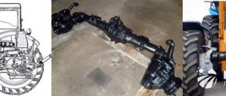
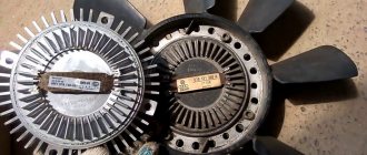
GAZ-66 vehicles are equipped with a compressor (Fig. 1) designed to inflate tires with air.
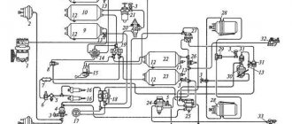
Compressors of cars with a tire pressure regulation system (GAZ-66-01, GAZ-66-02, GAZ-66-04, GAZ-66-05) differ from compressors of cars without this system (GAZ-66 and GAZ-66-03 ) by the fact that in the threaded hole of the compressor head above the inlet valve instead of a plug
the unloading cylinder is screwed in (Fig. 2).
The piston-type compressor, single-cylinder, air-cooled, is driven through a pulley together with the power steering pump by two belts from the engine crankshaft pulley. A compressor clutch is installed on the splines of the compressor crankshaft. The coupling is moved by a fork mounted on a roller, the position of which is fixed by a ball lock.
Ways to reduce fuel consumption
The consumption rate of GAZ is 66 with, for example, a Mercedes-Benz M316 engine installed with a displacement of 4.3 liters and a Mercedes manual transmission, which is reduced to 14.5 l/100 km when driving on the highway.
It is clear that when driving off-road, this figure is slightly higher - 18 l/100 km, but even this cannot be compared with more than three dozen liters of rated gasoline consumption per hundred kilometers.
Example of an engine from a Mercedes M316
Installing HBO on a carburetor
Another way to reduce fuel costs is traditionally to install gas equipment on a native carburetor engine. However, the experience of those who have made such an attempt shows that gas is not entirely suitable for the ZMZ engines installed on GAZ-66 due to the too low compression ratio in the engine cylinders.
The fuel consumption rate increases sharply to 45-55 l/100 km and no savings occur, especially if we take diesel for comparison. In addition, when installing LPG, there is a significant reduction in engine power, and its off-road operation becomes almost impossible.
In fact, the main advantage of “shishiga” over its analogues is lost. We should also not forget about the need to install gas cylinders, which eat up a significant part of the useful volume and significantly reduce the already not very large carrying capacity.
Diesel engine installation
So, if you are already, or are just about to become, the proud owner of a GAZ-66, and you are not satisfied with the really high gasoline consumption rate of your original engine, then the best option for you would be to look for a car with an already installed diesel engine or to independently convert it to a new engine.
self-installation of the engine on gas 66
Just keep in mind that replacing the engine necessarily entails replacing the associated gearbox. This significantly increases the budget of the entire event.
Therefore, if the only purpose of the modification is to reduce fuel consumption and, accordingly, financial savings on fuel, then such investments are justified only with constant use of the car. In the case when you take your “shisharik” out fishing or cutting wood only a couple of times a year, it will be cheaper to simply restore the original gasoline engine to good condition.
However, for those who, in addition to saving fuel, also need to increase the power and, therefore, the cross-country ability of the vehicle, installing a decent diesel engine on the GAZ-66 base is a completely justified investment of the money, effort and time spent. There are very few trucks that can compete with a diesel “shishiga” in overcoming the obstacles of full-fledged off-road conditions.
High fuel consumption
However, with all the advantages of the GAZ-66, it has several disadvantages, due to which it is now quickly being replaced by more modern cars. One of the most significant is the type of fuel selected for the engine. In all years of production, the Gorky Automobile Plant equipped this car with a ZMZ-513 carburetor engine (in recent years ZMZ-66-06).
carburetor engine ZMZ-513
Consumption, depending on modifications, is from 31.5 to 33.5 liters of gasoline per 100 kilometers - this was acceptable only for the USSR with its low price for both gasoline and diesel.
At the same time, do not forget that we are talking specifically about the concept of “consumption rate”, that is, about how much a fully technically sound car consumes when driving on hard surfaces.
GAZ 66 fuel consumption table
In modern conditions, with high prices for any type of fuel, such consumption is too high.
That is why many, in order not to give up the truly excellent all-terrain qualities of the car, remake it, installing a normal diesel engine from old trucks instead of the original carburetor engine.
We won’t talk much about the advantages that a diesel engine has over a gasoline engine in this article. We will mention only the main ones. Firstly, higher torque at low speeds allows you to operate the car engine in a more gentle mode in the most difficult conditions.
Modifications to the GAZ-52 engine
The following methods of struggle can be proposed. A lean mixture - here I propose a different ignition system: a thyristor, for a higher voltage. The ignition coil operates in a different mode and heats up less, despite more powerful impulses and additional leanness of the mixture at high speeds. Increasing the engine operating temperature to 90-95 degrees through a thermostat. As a result, oil consumption virtually disappears. The gasoline from the oil is all evaporated, and the oil becomes the viscosity it should be. The degree of combustion of gasoline increases, especially for 92 and 95, which is specific to us. From 76 it rises with poorly flammable additives - for example, diesel fuel. If the oil level is rising, it is much worse than if it is slowly falling. To organize oil cooling, there is a simple and slightly more complicated option. The first is to simply install an oil cooler from ZIL between the pump and the centrifugal cleaner - for the summer. There is another option to avoid reducing oil pressure by filtering and cooling it. This can be achieved by parallel supply of oil through the filter and radiator instead of a pressure sensor (through a tee). At the same time, we throttle the main flow by inserting a tube of 8 millimeters of internal cross-section into the filter pipe (for motors with a disposable filter in a tin housing). We put a copper coil in the crankcase of the oil system, and we supply water into it after the stove and have thermal stabilization of the oil to 110-115 degrees. In winter this will provide heating, in summer - light cooling.
In general, you need to climb into the crankcase, check the shaft journals to see if there are “foot wrappers” as thick as a candy wrapper. Enough mileage for 1000 kilometers. In general, for 2-4 days of fiddling, unless, of course, “pitfalls” are revealed.
Characteristics of the GAZ-66 compressor
One of the main advantages is its excellent performance characteristics, which allow it to effectively perform the assigned tasks. Among them, the following indicators deserve mention:
- cylinder size - 6 cm;
- system volume - 107 cm3;
- efficiency - 116 l/min;
- power - 1.22 kW;
- element cooling - air type;
- drive type - belt;
- shaft rotation indicators are 2000-2500 rpm.
The product is manufactured by the fuel and lubricants plant; new elements are provided with a six-month warranty. After this period, various malfunctions may appear in the device, which can most easily be eliminated using a special repair kit containing all the necessary components.
Checking the technical condition and repairing compressor parts
After disassembling the compressor to eliminate any malfunction, check the technical condition of its main parts.
If the wear of the cylinder exceeds the permissible level or its mirror is damaged, repair the cylinder to one of the repair dimensions indicated in the table. 2. According to these sizes, pistons and piston rings of repair sizes are produced.
The piston repair size group is indicated by numbers on the piston bottom: “+ 0.4”, “+ 0.8”.
Oversize piston rings are marked:
one strip 10 mm wide corresponds to an increase in the diameter of the ring compared to the nominal by 0.4 mm, and two strips - by 0.8 mm.
When repairing the crankshaft, use liners of repair sizes, the thickness of which is increased by 0.15 and 0.3 mm. The repair size group of the liner is indicated by numbers on its outer side: “—0.3” and “—0.6” (these liners have a thickness of 1.9 -0.013 and 2.05 -0.013 mm, respectively).
If nicks or annular grooves are found on the cylinder head plate valves, replace them and grind new valves onto the seats to obtain continuous annular contact.
Compressor malfunctions and ways to eliminate them
Reduced performance:
— Air leakage through valves or piston rings
— Clogged compressor air filter (for vehicles without a tire pressure control system)
— Weak tension of drive belts
Adjust belt tension
The compressor overheats:
Clean the oil lines and channels in the crankcase cover and the compressor crankshaft
— Carbon deposits on the piston and piston rings
Clean parts from carbon deposits
Throwing out oil with forced air:
— Wear of piston elbows or cylinder
— Violation of the oil supply seal to the compressor
Replace seal 14 (see Fig. 1) or rear compressor cover
— Broken seal spring
— Clogged oil drain pipe
Increased compressor knocking:
— Wear of pistons, pins or bearings
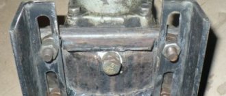
Compressor repair
Removal and disassembly of the compressor is performed in the following order.
— disconnect the oil outlet and supply lines, the supply hose and the air outlet line. Remove the compressor from the engine and then disassemble it
— remove pulley 10 (Fig. 1) of the compressor with assembled bearings;
— unscrew the locking screw of the compressor fork, remove roller 7 and fork 8 for turning on the compressor;
— remove clutch 9 for turning on the compressor;
— remove the compressor head and bracket 12;
— remove the connecting rod cover and remove piston 3 with connecting rod 2 assembled from cylinder 4;
— remove the front and rear covers, remove the seal 14 and spring 13 from the crankshaft socket;
— remove the compressor cylinder;
— compress the crankshaft bearings and remove crankshaft 1;
— unscrew plug 8 (see Fig. 2) of the discharge valve, remove spring 9 and valve 10;
— unscrew valve body 14 and remove spring 13, valve 12 and valve seat 15;
— unscrew plug 6 (see Fig. 1) or unloading cylinder; remove the piston pin and separate the piston from the connecting rod;
How to make a compressor with your own hands from a gas 66 compressor
This was done for design reasons. so that after installation it is convenient to drain the oil in place. when replacing
And here are the offal. I did not make an oblique incision. I also drilled a countersink. on the other side there are two more holes along the axis of the connecting rod.
It was done a long time ago. in 1993. for installation on karakat. but the plans were not destined to come true. Worked for a long time. 6 years old, just like a garage one. Nothing . condition of the crank and piston. like new.
Official data (l/100 km)
Gas 66 came with a huge eight-cylinder engine, the volume of which was 4.2 liters. The power figure here reached 120 horsepower. The pair was made up of a manual gearbox operating in four modes. All-wheel drive was also always installed, with the ability to disable the front axle and lock any of the differentials.
Fuel consumption per 100 km here was simply huge - 30 liters. This version of the car was equipped until 1991. Afterwards, this unit was slightly modified, increasing power to 125 horsepower, and also reducing gasoline consumption to 25 liters.
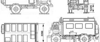
GAZ 66 technical specifications
A liquid-cooled engine was installed under the truck cab. The GAZ 66 engine is an 8-cylinder V-shaped engine and is lighter than its predecessor, the GAZ 63.
The engine capacity of the GAZ truck photo, the photo of which you see, was 4.25 liters, and the power indicators were 115 horses.
During the development of the power unit, the design had a number of unique design solutions. On the sides of the car in its lower part, two fuel tanks were installed on both sides, each holding 105 liters. The K-126B carburetor engine, two-chamber, balanced, with a falling flow, was quite economical, and the fuel consumption of the GAZ 66 truck was 20-21 liters per 100 kilometers. Starting in 1993, a diesel unit was installed on the 66 model.
The 4th manual transmission interacted with the power unit, located on the right side of the driver behind him. It took some time to get used to such a non-standard arrangement. The transmission also included a two-stage transfer case and a hydraulic clutch.
The GAZ 66 compressor is single-cylinder, powered by a power unit, with the function of automatically maintaining uniform tire pressure. It began to be installed on the GAZ-66-11 model in the mid-80s.
GAZ 66 wheel sizes in the range 12.00-18. Special rubber made the truck more stable, with good cross-country ability in mountainous and swampy areas. The tires allowed the GAZ 66 truck to easily cope with mud, overcome rocky surfaces, snow and mush.
For all its positive qualities, the car was clumsy when turning. The radius was 19 meters. We had to perform maneuvers to change the direction of movement. See the video of GAZ, its maneuvers and technical capabilities at the end of the article. The length of the car compared to the GAZ-53 became 3740 mm longer and amounted to 5655 mm. The width indicators have increased: 2342 versus 2380 for the GAZ 53.
GAZ 66 price
The production of the legendary truck stopped a long time ago, but it can still be found on our roads.
The machine, which was actively used in various fields of the economy, including in the army, is being sold today. Many offers can be found on the Internet. Today the price of a car is affordable, on average - from 150,000.00 to 350,000.00 rubles. Kung-type trucks are in high demand. They are being converted to transport people.
They cost approximately RUR 400,000.00. On-board modifications on the secondary market are offered for RUB 250,000.00.
Car GAZ 3302: characteristics, device, diagram.
Technical characteristics of KamAZ 5410 here.
Read the review of the KamAZ 54115 truck in this article.
Basic faults
There are several breakdowns that can significantly worsen the performance of the compressor or lead to its complete failure. Among them, the most common problems deserve mention, which include:
- decreased productivity;
- element overheating;
- oil release;
- increased noise during operation.
Each of these cases requires separate consideration, since it can be caused by various reasons. When power is reduced, problems are most often caused by air leaks in the system, clogged filter elements, and weak belt tension.
Overheating of the compressor can be caused by the lubrication system in the presence of contaminants, as well as the formation of carbon deposits in the piston system. No less often you have to deal with oil leakage, which occurs due to excessive wear of the piston ring seals, spring mechanism, and oil drainage channels. A knocking sound in the system occurs when components are worn excessively.
Recommendations for choosing a compressor model
When deciding which compressor to buy for your garage, you should take into account that the connecting rod-piston group of an oil compressor has a significantly longer service life than that of an oil-free compressor.
In addition to the main characteristics of the compressor - performance and operating pressure, it is also necessary to take into account the requirements imposed by garage conditions. This is due to the lack of free space and the state of the electrical network. For garages, cottages and other household needs, it is recommended to use household compressors with low electric motor power. This is due to the fact that in most garages, and even in summer cottages, electrical networks are in very poor condition. Sometimes even a low-power household compressor does not have enough voltage to achieve the required pressure, for example, 6 atmospheres.
An example of a suitable device is a household coaxial compressor with a power of approximately 2.5 kW, equipped with a 50 liter receiver. It can be used for almost all types of painting. An example of compressors of this class can be chosen, for example, model GM50300 from the Italian company Fiac with a 50 liter receiver and a suction capacity of 300 liters per minute.
Compressors of another series from Fiac are equipped with a V-shaped 2-cylinder compressor head, a 50 l receiver and have a suction capacity of 400 l/min. For example, model VX5040. A similar model, the Corsair 402M compressor from Fini, has a 25 liter receiver and a similar V-shaped 2-cylinder compressor head. These models require a high quality electrical network.
If you use a compressor every day, you should buy a more efficient device with a receiver volume of more than 50 liters. One of the possible options is a professional axial 2-cylinder compressor Remeza SB 4/S50 or SB 4/S100 jointly produced in Italy and Belarus.
The proposed models have a suction capacity of about 280 l/min and a receiver volume of 50 and 100 l, respectively. These models are very popular among garage painters with constant volumes of work.
For one-time painting work, a relatively cheap 11.5 kW piston compressor with a 20-25 liter receiver, for example, the Euro25 model from Fiac, is quite suitable. A small diaphragm compressor can also be used to solve these same problems. These compressor units can completely supply compressed air to a small spray gun or airbrush.
A compressor of lower power loads the electrical network to a lesser extent and can be used as a backup device.
DIY garage compressor
Some specialists who have experience in making various devices on their own can make a homemade compressor for the garage and save money on purchasing a serial compressor.
As a basis for a homemade design, you can take a compressor from a GAZ-66 or ZIL-130 car, an electric motor and a couple of receivers. The compressor with the bottom cover removed is installed through a paronite gasket on a fragment of a channel 20-25 cm wide. The engine is similarly installed in milled grooves to create the required tension on the drive belt. Large cross-section belts should be avoided, as they take a lot of power from an already fairly low-power engine, especially one operating on one phase.
Autoclub GAZ 52
GAZ-52 is one of the most famous Soviet trucks that belonged to the family of medium-duty vehicles of the 3rd generation of the Gorky Automobile Plant. Serial production of these legendary trucks began in 1958 - the last modification of the GAZ-52-04 rolled off the factory assembly line in 1989 (according to other sources, this happened in 1992). From 1958 to 1959 the car was produced under the symbol GAZ-52F, from 1966 to 1975 as GAZ-52-03, from 1975 to 1989 as GAZ-52-04. The people called the beloved, unpretentious domestically produced truck GAZ-52 nothing less than the “workhorse” of the economy of the Soviet Union. In total, a little more than 1 million trucks were produced.
Initially, the load capacity of the GAZ-52 was at around 2.5 tons - a little later this figure increased to 3.5 tons. The car was equipped with a unified cabin, like the GAZ-53 model. Despite the use of many common parts, the GAZ-52 and GAZ-53 still differed from each other in their wheel rims: the rims of the GAZ-52 and its various modifications had 6 ventilation holes and had narrower tires. In case of damage, the disks were replaced with new ones without much effort.
It is impossible not to note the wide range of GAZ-52 trucks: flatbed trucks GAZ-52-01 and GAZ-52-02 with 2 wheelbase options (3300 and 3700 mm, respectively). 1959 - the 1st batch of the GAZ-52F chassis was produced. 1961 - the beginning of production of the GAZ-52-03, equipped with a cabin from the GAZ-53A. In 1975, the GAZ-51A, which came off the factory assembly line, was replaced by a similar-sized truck, the GAZ-52-04, which was visually a vehicle on the GAZ-51 chassis and with a cab from the GAZ-53A.
Modifications GAZ-52-05, GAZ-52-08 and GAZ-52-09 are taxis designed for cargo and passenger transportation. It should be noted that the GAZ-52-09 was equipped with special equipment for operating on liquefied petroleum gas (LPG); A-76 gasoline was used as backup fuel. Among other things, the production of the GAZ-52-06 truck tractor, created to work with a semi-trailer weighing 4 tons, was launched. To operate on LPG (liquefied petroleum gas), the GAZ-52-07 modification was converted on the basis of the GAZ-52-04. Modifications of GAZ-52 dump trucks were made at the Saransk Automobile Plant.
During the existence of the Soviet Union, the GAZ-52 and its various modifications were exported to countries that were part of the bloc of socialist powers. Mostly the “workhorse” of the Soviet economy was supplied to the GDR, Hungary, Czechoslovakia, Poland, Yugoslavia, Finland, Cuba, Vietnam, North Korea, Laos and Mongolia. Despite the fact that a sufficient amount of time has passed since the official cessation of serial production of this truck (more than 20 years), in certain regions of the Russian Federation you can still find perfectly functioning representatives of the 3rd generation of GAZ vehicles.
Specifications
Engine and transmission
GAZ-66 was one of the first cars in the USSR to receive a V-shaped power unit with 8 cylinders. It was produced at the Zavolzhsky Motor Plant (ZMZ) and in a number of parameters was unified with the GAZ-13 “Chaika” engine. Engine capacity 4254 cc. cm produced a power of 120 horsepower, reaching 3500 rpm, which at that time was considered quite sufficient for off-road driving.
In the early 1990s, a diesel engine was used as a power unit for the GAZ-66-40 and GAZ-66-41 modifications (turbocharged and air-cooled in the first version) with a power of 116 and 85 hp, respectively. s., but few such cars were produced.
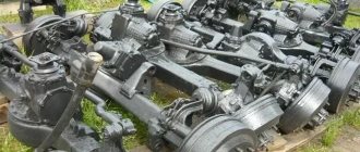
Suspension type
The suspension at the front and rear is of the dependent type and has a similar structure. It was mounted on longitudinal semi-elliptical springs, the ends of which were located on rubber supports. The smooth running of the machine was achieved due to telescopic hydraulic shock absorbers.
In addition, the GAZ-66, having a well-balanced center of gravity, has almost equal load on the rear and front axles. At the same time, the overall strength of the suspension did not have a large margin, so it was extremely undesirable to overload the car.
Maximum speed
The truck could accelerate to 90 kilometers per hour, but the maximum speed was structurally restrained by a limiter. When it was removed, the maximum speed increased to 110-120 kilometers per hour, but the working life of the motor was significantly reduced.
Fuel consumption
Covering a distance of 100 kilometers required the GAZ-66 to consume 20-25 liters of AI-76 or AI-80 gasoline. The car had two tanks with a capacity of 105 liters of fuel each; their full refueling provided a range of 800 kilometers. The diesel version of the engine was noticeably more economical and consumed a maximum of 17 liters of fuel per 100 km.
Dimensions and weight
| Options | Values |
| Length | 5655 mm |
| Width | 2342 mm |
| Height | 2440 mm |
| Wheelbase | 3300 mm |
| Ground clearance | 315 mm |
| Curb weight | 3470 kg |
| Load capacity | 2000 kg |
| Maximum weight | 5940 kg |
Front axle and track width
The Gas-66 front axle included a gearbox and constant velocity joints, used instead of axle shafts. Maintaining reliable vehicle operation on public roads required changing the oil in the axles after 50-70 thousand kilometers on roads and even more often when operating in off-road conditions. Crossing water barriers required mandatory subsequent injection at the first opportunity.
Maintenance of a garage compressor during operation
Careful and regular maintenance of the compressor will extend the life of the unit and avoid breakdowns. It is recommended to carry out the following preventive measures.
Periodically clean or replace the filter. A non-woven material resembling a padding polyester is used as a filter. If the compressor is located in the same room where spray painting is being done, the filter often becomes clogged with sticky paint particles, which subsequently dry into the filter material and reduce its throughput.
This filter must be replaced with a new one.
Experienced garage technicians will improve their compressors by installing automotive-type air filters on them, which have much less resistance to the intake air and have better filtering qualities.
Such an upgraded filter increases the service life of the compressor, since it achieves a higher quality of filtration of abrasive particles contained in the air. As a result, the piston pair wears less and the service life of the compressor increases. Car filters are freely sold.
- Periodic oil change. Use only synthetic compressor oil for this;
- Periodic draining of condensate from the receiver. For this purpose, a special valve is provided at the bottom of the receiver. Before opening the valve, be sure to relieve the pressure in the receiver;
- Periodic cleaning of the electric motor and compressor cylinder from dust and dirt, which significantly impairs the cooling of working units.
After completing work, be sure to release the compressed air from the receiver, in which the compressed air should not be stored for a long time.
Homemade compressor (photo and detailed description of manufacturing)
I made a homemade air compressor: a detailed photo report on the manufacture of a compressor based on the ZIL-130 head.
Greetings DIYers!
I needed a compressor for a home workshop, somewhere to blow something out, pump up tires or paint some small thing.
Initially, I wanted to buy a ready-made (Chinese) solution in a budget of up to 10 thousand rubles, but after searching for information on compressors I realized that everything was sad there. You need 15+ about money to buy this miracle equipment and then not regret the money spent.
As a result, I was ready to repeat the feat of many and get in touch with the legend of the domestic Soviet automobile industry called the ZIL 130... In addition, in the technical department I studied to become a truck mechanic, then I studied this Zil-130 car and the MTZ-82 tractor completely, down to the bolt three years, the entire academic period!
What good things can I say in favor of this compressor head... Its most important advantage is that it is not “killable”! Almost all spare parts are available and are not expensive. You can always find parts by article number and order. Its lubrication system comes under pressure from the engine oil line, and the same goes for the cooling system. The compressor head works continuously as soon as the engine starts. After reaching 7.5 atm, in the brake system, the head goes into idle mode and begins to pump air from one cylinder to another. Operating temperature is approximately 90-100C. This is exactly the temperature our engineers designed it for. Something like this... After reading a bunch of forums and watching “all” the videos on YouTube, I realized that there are different opinions on these compressors. Personally, I wanted to make it simpler, the better. Therefore, it was decided to make a lubrication system with “scoops”, like everyone’s favorite legend SO-7b, and a cooling system with natural circulation in the form of an expansion tank... and that’s it! To begin with, I looked for a used head for a long time on Avito and Yula... in the end I found it for 1500 rubles. The seller said that it also once worked as a garage compressor, but not for long... Its condition was simply terrible. But there were no other options, I had to buy it. As a result, I cleaned all the cord with a brush on an angle grinder and the look has already become better.
It was black inside, as it later turned out, it was very overheated and the oil stuck to the walls.
The condition inside is terrible... I had to soak the whole thing for days in solvent and gasoline. The rings on the pistons were all stuck. To dismantle them, I had to pick them up with a screwdriver and knock them out with a hammer... and the rings broke in small pieces. No solvents decarbonized them. Afterwards I ground the head and surface of the cylinder.
Factory quality, like something out of a chainsaw, so I’m not going to bother either.
Oddly enough, the cylinders turned out to be free of scoring. The hon is even visible (no photos). The piston at TDC of the cylinder is practically free of play. The pistons themselves were also in pretty good condition. The crankshaft journals are free of scuffs, but the bearings already have some play. Therefore, new liners, bearings, a set of gaskets, a set of rings, studs and a set of intake and exhaust valves were purchased - disgusting quality. I decided to do the lubrication system, as I wrote above - “with scoops”. To do this, you need to drill the block itself for the breather, then two holes in the connecting rod and a third in the yoke for the scoop itself.
There is an M10 thread for the breather.
The yokes have M6 thread.
tubes are glued to thread locker
In order for these scoops to work, you need to weld the oil pan. As it turns out, I didn’t take any photos. Everything is simple there. Four corners on the edge and the plate is welded on the bottom. At the same time, fitting for the site is underway...
The motor will be installed 3 kW 2900 rpm three-phase in a single-phase network. I decided to make a single platform for the engine and head. It will also be removable from the receiver.
Engine tension grooves.
The tank, like everyone else, is a 50L propane tank with wheels.
As I already wrote, the platform will be removable.
Next, a drain bolt was naturally welded on the bottom of the cylinder to drain condensate and two nipples from a half-inch pipe for a pressure gauge and pressure switch. I changed the wheels a little to others with a wide tread))) The third leg also has a rubber gasket. All these rubber products help against vibration. Well, for painting...
The connection to the compressor head was made rigid, from a half-inch pipe. The non-return valve was installed using a plumbing one, with a brass core.
The condition of the electric engine was also not very good. And besides, it is after the bulkhead. These craftsmen decided that three wires would be enough and connected the whole thing using a star circuit. Therefore, I had to open the whole thing, look for the missing wires, and pack everything back again. Clean it from dirt, paint, varnish and only then paint it...
I decided to paint the compressor head orange... for me this is the color of joy. At least paint this product somehow.
An oil pan with a drain hole is screwed to the bottom. I also made a plug bolt with a neodymium magnet to catch metal impurities. Because after the first launch and a short run-in, after disassembling the pallet, I saw a lot of metal shavings.
The coolant tank is made from a piece of pipe with a diameter of 150mm. Connection to the “hard” with American women.
The tank for crankcase gases is from a classic, like all homemade ones. I made the air filter myself. Because they sell for 300 rubles with foam inside, they scared me away. To do this, you will need the filter element itself from Izh, Moskvich2141 and polypropylene fittings and pipes.
I cut a thread on the pipe for this plug.
Now regarding the revolutions... I decided to make a compressor with a speed of 2000 on the crankshaft of the head. To do this, I spent a long time searching for a suitable pulley for the electric motor. On the head itself there is a standard pulley with a size of 218 mm in outer diameter. According to the online calculator, I needed a drive pulley with a size of 150mm. Therefore, I bought a pulley from a VAZ 2101-07, which is located on the crankshaft to drive a fan or pump. It doesn’t matter. Its dimensions are just 150mm and the inner one is 29mm. Since I have a 24mm seat size on the motor shaft, I had to grind out the bushing myself using a grinder and a file. Before this, I was looking for turners in my village... but you won’t find them during the day!
At these speeds, a 50L cylinder pumps up to 8 atm in 1 minute 40 seconds.
An oil tank with pipes from the breather and crankshaft. If in the future you need to convert it to forced lubrication, then there are absolutely no problems. The main line is connected to the standard place and forward.
The return from the oil line is discharged through the drain hole.
The belt tensioning mechanism is incredibly simple. We put any belt on the pulleys, pull the engine, then bring the bar from the corner. We pull it to the frame and then tighten the belt with tension bolts. Afterwards the electric motor platform is attracted.
Air filter.
Check valve... Ignore the two pressure gauges. Later, automation will be purchased and installed in place of one of the pressure gauges.
I inserted a thermometer into the coolant reservoir.
The wheels and stop are made of thick rubber - ala anti-vibration!
If you need to paint something for a long time and with a large load, you can connect a hose from the water supply to this tee and force cool the head. I don’t think there’s any need to explain, it’s on your fingers...the tank is detachable on American models.
Well, I bought this oil. With the smell of an ordinary spindle.
Now, let’s look a little at the electrical diagram and try to calculate the approximate cost of the compressor parts. So, we have a 3 kW engine, 2900 rpm and a consumption of 11.8 amperes in a 220 network when connected in a triangle.
This engine was being repaired and the craftsmen only installed three wires to connect to 380V. Therefore, we had to go through the whole thing and bring out more additional wires. There are plenty of videos on YouTube on how to do this. Next you need to select working and starting capacitors. There is a small ambush here. There are different online calculators and they show completely different values...on some there are 200 microfarads working and 400 microfarads starting, on others 400 and as many as 800 microfarad starting. And that’s why you don’t know what to buy. I decided to do this, buy the minimum first and bribe if there is not enough capacity. Prices for capacitors with high capacity are incredibly expensive. To connect, you will need starting and running capacitors, a time relay, and magnetic starters.
Working at 120 and 100 microfarads Starting at 500 microfarads.
Time relay TDM with time adjustment 0.5s -3min.
And two magnetic starters... one unloads the power supply to the electric motor, the second is a time relay starter.
I collect it in a box. We attach the contactors with relays to self-tapping screws, and the contactors to ties.
My compressor does not yet have an automatic system (pressostat), so I connected it this way. Let me explain in words... the power cable from the socket goes to the push-button station. At this time, the lamp lights up, indicating that there is voltage (mains). After starting the push-button station, voltage goes to the contactors and the coil of the ABB magnetic starter and the TDM time relay. From the ABB magnetic starter, the current flows to the motor with working capacitors and in parallel the current flows through the TDM time relay to the coil of the second (black) magnetic starter. The second MP already connects the starting (blue) capacitor and the engine starts. After a certain time (I have 2s), the time relay works and the second (black) magnetic starter turns off. For those who understand electrical engineering, it’s all simple, but most people and I can’t figure it out right away either! If you need to set a different time, then open the box cover and turn the regulator on the time relay.
Now for the Conders. The first start of the engine without load at idle showed that there were too many condensers. The engine warmed up in a couple of minutes. Therefore, I removed one 100 microfarad condenser immediately. Then I assembled the compressor and installed a small pulley (70mm) on the engine. The engine with the compressor head ran smoothly, without humming or heating. I started the compressor at 8 atm calmly. After installing a pulley with a diameter of 150 mm, the engine could not even start with 0 atm in the cylinder. As a result, I threw a second one at 100 microfarads and everything worked as it should. The operating time of the starting capacitor has of course increased. If the network is 220V and the compressor is warm, then with 8 atm in the cylinder it starts easily. If there is a drawdown in the network to 200V, then it cannot start at 8 atm. It turns the pulleys and there is not enough acceleration in these 2 seconds, but closer to 5 atm in the cylinder it starts. You can, of course, increase the time on the relay... it’s just a little short of unwinding... but I won’t do that for now. And all this without an unloader valve and an inlet pre-receiver! Photo of the finished product
Homemade compressor - do it yourself
A compressor in the garage will always come in handy: pump up the wheels, paint them, “blow out” any parts, etc. Somehow I came across a single-cylinder compressor for a GAZ 66, an electric motor and a pair of receivers; I took the main ideas from the Internet. Therefore, I will not dwell on the principle of operation (everything is clear), but I will only post a photo and a short description of a homemade compressor for the garage . Receivers Two scuba tanks turned up by chance, which gave birth to the idea of building a compressor. There are two drain valves at the bottom to drain condensate. On the right receiver there is an outlet valve, on the left there is a hose for connecting the containers to the compressor.
I attached three wheels, weak, but enough to move around the garage, the top one with a turning axle. The wheels are taken from an old medical cart. devices.
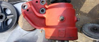
Crankcase for a homemade compressor The GAZ 66 compressor was missing a crankcase cover, so I had to make a homemade one. I used a pipe sector with a diameter of 300 mm and a thickness of 5 mm. The edges of the sector were bent and leveled into a plane, and a 25X25 mm corner was welded to the ends. I cut off the excess corner. I drilled a hole in the bottom of the lid and installed a drain plug (10 mm bolt). I made guides for fastening from a 30x50 mm corner.
Manifold for instruments The receivers did not have additional holes for installing instruments (pressure gauge, emergency sensor). I thought for a long time about what to make a manifold from to install them on the pipeline. The idea arose to use the old VAZ clutch master cylinder. At first glance, everything is simple - weld two fittings and that’s it. But I was faced with the fact that it is impossible to make a high-quality weld, the metal from which the cylinder is made contains a lot of carbon. It “boils” during electric welding, welded it in several layers, filled it with glue from the inside to seal it. Later, this technology did not justify itself, and the collector was replaced by the GAZ-66 receiver, which has enough holes for instruments.
DIY compressor layout. Electric motor 1.5 kW, three-phase 220/380, 1500 rpm. installed on skids, it can be moved to tension the belt. secured with 4 M10 bolts. The compressor is mounted on skids with crankcase cover bolts.
Starting capacitors of a homemade compressor For the operation of such an engine, according to calculations, it is necessary to run 152 μF and release 250 μF, but it turned out to be sufficient for operation and starting at a pressure of up to 4 ATM C = 106 μF. But if the pressure is higher, then it is necessary to add a starting capacitor. I estimate that at a pressure of about 8 ATM, the standard power will be 1.2 kW, at 4-5 ATM it will be lower. Conclusion: the capacitor capacity I selected is sufficient. Capacitors of different types for breakdown voltage 500-630V are placed in boxes around the engine. The boxes are fixed to the frame and covered with a steel casing. The capacitor housings are insulated from the compressor housing with rubber gaskets. Gas station 10A was used for switching on. Connection to the network is carried out using a 3-wire circuit (the housing is connected to ground). The picture shows a homemade air filter. Made from a bottle of injector cleaner and a coffee can, with mesh and foam inside.
Compressor drive and cooling. A VAZ 2101 belt is used for the drive. The drive pulley is homemade, the driven pulley is from a ZIL 130 compressor. For cooling, a VAZ 2121 fan is placed on the compressor axis on top of the pulley and centered with a washer. The drive is protected by a casing.
Crankcase lubrication and ventilation. To improve lubrication of the crank mechanism, three holes are drilled in the connecting rod and bearings. The central channel of the crankshaft is connected to the container (GCS tank of a VAZ car) with a flexible oil-resistant hose. Excess oil enters it; when the compressor is running, oil can also be added. A special feature of the GAZ 66 compressor is that it is single-cylinder; during operation, the pressure in the crankcase changes, which is not desirable. I got rid of the shortcoming: I drilled a hole in the body, cut an M10 thread, screwed in a fitting and connected it to the oil tank. I enlarged the hole in the tank lid to 8mm and installed a rubber membrane with slots.
General view of the compressor.
All parts are covered with shields made of 1.5 mm steel. That's all. The idea arose to add a box to save space in the garage, of which there is never too much.
Place for tools. An aluminum box was attached to the top of the engine and the “battery” of capacitors. I plan to store tools and accessories in it. Seen in the photo at the beginning of the article.
Features of operating a garage compressor in winter
There are some features of operating a garage compressor in winter:
- Before loading the compressor, it is necessary to let it run idle for 5–10 minutes to warm up the thickened oil in the crankcase;
- After completing the work and disconnecting the compressor from the network, slowly bleed air from the receiver through the working hose. Along with the air, the water that has accumulated in the receiver and hoses will be removed from the receiver.
This must be done immediately, before the compressor has time to cool down and the condensate has time to turn into ice. When the pressure in the receiver approaches zero, the remaining condensate that has not escaped through the hose should be released through the condensate drain valve.
However, during the frosty season, certain problems sometimes occur:
- It is possible that the hoses may become clogged with ice and the valve may freeze while draining the condensate. In both situations, it is necessary to warm up the frozen areas with a hairdryer;
- When taking air with long pauses, the compressor has time to freeze and may not start when the automation gives the command to start when the pressure in the receiver drops to the minimum permissible value. At the same time, the electric motor hums, but cannot start rotating. You should immediately disconnect the compressor from the power supply, completely bleed the air from the receiver, and then restart.
Low pressure wheels for Gas-66, 33081, Zil-131, Ural, Kamaz, Unimog and heavy all-terrain vehicles.
Ya-190 15.00-20 1300x410-20
| Size | 15.00-20 BC |
| Outside diameter | 1300mm |
| Profile width | 410mm |
| Landing diameter | 20″ |
| Grouser height | 25mm |
| Layering | 4 |
| MAX load | 2000kg |
| Weight of wheel with disc | 97kg |
| The cost of a tire with a GAZ-66 rim | |
| RUB 35,700 |
This low-pressure tire was created specifically for installation on vehicles such as GAZ-66, 33081, etc. in order to increase their maneuverability on weak-bearing soils. Its element is mud and deep forest ruts left by heavy timber trucks. The height of the tire will allow cars like GAZ-66 to increase their ground clearance and overcome forest ruts without “sitting” on bridges. Compared to the standard tire for GAZ-66 12.00-18, this tire has a height of 1300 mm, versus 1084 mm, which increases the clearance by more than 10 cm. And the profile width is 73mm larger (410mm versus 337mm). Working pressure in the tire is from 0.3 to 0.8 atm. Increasing the diameter and width of the tire profile and reducing the internal pressure gives a larger contact patch with the surface, thereby increasing the vehicle's cross-country ability.
Features: For installation on a car type Gas-66 or 33081, a body lift of 15 cm is required. Installing this tire keeps the car in the 2.55 m overall size, which allows it to drive on public roads. Supplied with a disc with a 2-sided beadlock. Recommended pressure 0.3-1.0 atm
VI-3 1300x530-533
| Size | 1300x530-533 |
| Outside diameter | 1300mm |
| Profile width | 530mm |
| Landing diameter | 21″ (533) |
| Grouser height | 20mm |
| Layering | 4 |
| MAX load | 2000kg |
| Weight of wheel with disc | 98.5kg |
| The cost of a tire with a GAZ-66 rim | |
| RUB 50,800 |
The new modification of the VI-3 tire has 4 layers of rubber cord and a maximum load of 2000 kg per wheel. The tire is available in a tubeless version. Self-cleaning tread pattern - an oblique Christmas tree gives the tire the highest traction properties, reducing slipping. Installing this low-pressure tire on such GAZ-66 and 33081 vehicles significantly increases cross-country ability. There will also be an increase in vehicle clearance (thanks to the tire diameter of 1300mm), and the tire profile width of 530mm (1.5 times larger than a standard 12.00-18 tire) will allow you to confidently overcome off-road areas, muddy mud and deep forest ruts. The weight of the VI-3 wheel (98.5 kg) mounted on the disk is identical to the weight of the standard wheel (97 kg).
Features: For installation on a car type Gas-66 or 33081, a body lift of 15 cm is required. Installing this tire keeps the car in the 2.55 m overall size, which allows it to drive on public roads. Supplied with a disc with a 2-sided beadlock. Recommended pressure 0.3-1.0 atm
Bel-91 24.0/50-22.5 1150x620-22.5
| Size | 24.0/50-22,5 |
| Outside diameter | 1150mm |
| Profile width | 620mm |
| Landing diameter | 22,5″ |
| Grouser height | 40mm |
| Layering | 4 |
| MAX load | 3500kg |
| Weight of wheel with disc | 148kg |
| The cost of a tire with a GAZ-66 rim | |
| RUB 54,300 |
The low-pressure tire Bel-91 24.0/50-22.5 has an outer diameter of 1150 mm and a profile width of 620 mm and is similar in size to the arched tire Ya-170a 1140x700. Increases vehicle cross-country ability on weak-bearing soils: mud, loose soil, waterlogged soil, snow, sand. The tire has 4 layers of cord and can withstand a load of 3500 kg at a pressure of 1.3 atm. Due to the properties of low-pressure tires and high load-bearing capacity, the tire can be used for installation on trucks such as GAZ-66, GAZ-33081, ZIL-131, URAL, KAMAZ, UNIMOG. It is equipped with a camera and a special wide disk with bolt holes for installation on GAZ-66, GAZ-33081, ZIL, URAL, KAMAZ, UNIMOG and other vehicles.
Features: For installation on a car like Gas-66 or 33081, a body lift of 5 cm is required. Installing this tire takes the car beyond the 2.55m clearance. It is equipped with special discs with mounting holes for GAZ-66, URAL, KamAZ, ZIL, and you can also make any disc to order. Recommended pressure 0.3-1.3 atm