The MTZ-82 tractor, popularly called “Belarus”, has many advantages. It is reliable, passable and maneuverable due to its relatively small dimensions. This equipment is powerful, so it can be used to perform a wide range of agricultural work.
However, even such time-tested equipment fails. Most often, problems arise with the MTZ-82 front axle. To deal with the breakdown and repair the equipment yourself, you should study the design of the front axle and the main problems that may arise with it.
Description of the front axle MTZ 82
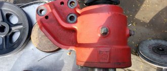
The front axle in the MTZ-82 tractor is of portal type. This means that the beam is not aligned with the wheels. Thanks to this, the tractor has the necessary agrotechnical clearance, which allows for machine processing of crops with tall stems (Figure 1).
Note: This front axle is installed in the opening of the front beam of the semi-frame.
RVD hoses are connected to the housings of the axle shafts of wheel reducers using telescopic technology. This allows you to adjust the track of the front drive wheels in the same way as the rear ones, steplessly. The front axle self-locking differential is automatically engaged when the axle is engaged.
The front axle is driven by a gearbox through a transfer case and a cardan drive with an intermediate support. This approach allows the use of automatic and forced activation of the transfer case.
Figure 1. Front axle is one of the key parts of the tractor
In addition, the front axle can be switched off completely. This is usually done during transport work to reduce fuel consumption and reduce tire wear.
Also, the front axle drive is equipped with a friction safety clutch. It is mounted to the intermediate support of the cardan transmission. This part prevents drive failure during short-term bridge overloads.
MTZ transmission and its operating principle
The all-wheel drive type of mechanism is a small frame that serves as a housing for the MTZ gearbox, clutch and rear axle.
In some models of Belarusian tractors, the transmission is equipped with a transfer case, FDA, and cardan transmission.
The main task of the MTZ transmission is to transmit torque from the engine to the MTZ front drive axle. This process involves the clutch, gearbox, rear drive axle, and transfer case.
The latter mechanism operates in three modes:
- When the rear wheels of the tractor are turned off, the FDA is turned off;
- Forced engagement and engagement of the FDA.
Thus, with the help of the MTZ 82 front axle, agricultural machinery is controlled.
Circuit and device
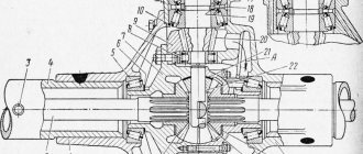
The main function of the front axle is to transmit torque to the drive wheels. It is transmitted from the engine through the driveshaft (Figure 2).
Note: Thanks to this torque, the tractor moves forward and the steered wheelset is stabilized.
The front axle diagram includes the following elements:
- Central gear;
- Support beam;
- Self-locking differential;
- Bevel gearboxes.
The front axle is connected to the support beam of the half-frame. Thanks to this, a certain mobility of the part is achieved. This type of connection is called semi-rigid.
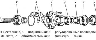
Figure 2. Main components of the bridge: 1 - track adjustment mechanism, 2 - bridge cover, 3 - cuff body, 4, 20 and 21 - shims, 5, 23 and 25 - bearings, 6 and 28 - nuts, 7 - driven gear , 8 — drive disk, 9 — pressure cup, 10 and 11 — differential housings, 12 — driven disk, 13 — breather, 14 — axle housing, 15 — side gear, 16 — side gear plug, 17 — differential bolt, 18 — satellite axis, 19 - satellite, 22 - drive gear housing, 24 - drive gear, 26 - adjusting washers, 27 - connecting flange, 29 - wedge, 30 - semi-frame beam, 31 - beam bushing, 32 - locking strip, 33 - axle rocking
To prevent the bridge from swinging, there are special protrusions in the lid and body that act as clamps. The main gear and differential are located inside the structure.
The differential consists of two parts. They contain 4 satellites, paired axles and gears, blocks with friction discs and two pressure-type bowls.
Device of portal FDA MTZ 82
The supporting beam of the bridge consists of a main gear housing 23 and a cover 2, or in a new version of three parts (a housing and two sleeves) connected by their flanges with bolts. The beam is attached to the tractor semi-frame with an articulated joint, providing lateral rolling within 8-9°, reacting to road unevenness. The housing houses a bevel pair of gears with helical teeth of the main gear and a differential mechanism. The sleeves contain movable housings for the axle shafts of the wheel reducers. Changing the track is carried out by screw mechanisms, the rotation of which extends the casings with wheels relative to the bridge body. The track is fixed by locking wedges 31 in the left and right screw mechanisms 1.
FDA diagram
Also for reference, it should be noted that the early MTZ 82 tractors with power steering steering were equipped with FDA with hubs for 5 wheel mounting studs. Later tractors with steering under a metering pump (HSU) are equipped with units with 8 studs on the hubs. In addition, the old bridge is distinguished by an increased size and shape of the casting of the main gear housing with the differential. The casting has an extended part on the left axle shaft (along the tractor), that is, the body is cast in one piece with the left axle shaft sleeve. You also need to pay attention to the configuration of the side of the bridge, where the details may also differ. The new bridge has a symmetrical beam design of three parts, connected at their flanges by bots - the central part of the housing for the main gear with a differential and two sleeves of the axle shafts.
Old bridge MTZ 82
FDA MTZ 82 with 8-stud hubs
main gear
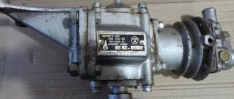
A pair of gears is installed in the axle housing 23, receives longitudinal torque from the FDA drive cardan shaft, converts it into transverse torque relative to the tractor axis and transmits it to the differential.
Main pair of front driving wheels MTZ 82
The driving helical bevel gear 13 is made integral with the shaft, which receives rotation from the cardan drive transmission. The splined shaft shank is fitted with a flange 9 for connection with the corresponding flange in the cardan shaft. The threaded end of the drive gear shaft is tightened with nut 10, simultaneously providing adjustment of the clearance in the rotation bearings and flange mounting. The shaft itself is placed in a glass 5 on two tapered roller bearings 6.7. The front bearing is rigidly pressed onto the shaft, the position of the rear bearing is set using adjusting washers 12. The cup assembly with the drive gear and installed bearings is mounted in the bore of the axle housing 23, and tightened with bolts at the flange connection. In the bore, the cup is sealed with a rubber ring, and the drive gear shaft is sealed with a self-clamping oil seal 8, pressed with the holder into the bore of the cup. To prevent oil back-up, an oil deflector ring 11 with helical grooves on its outer diameter is installed in front of the oil seal.
The driven gear 14 is installed on the splines and centering belt of the differential housing 15.19. To prevent axial movements, the gear is tightened with a nut. With the differential, the driven gear rotates on two tapered roller bearings 21, one of which is located in the housing 23, the other in the axle cover 2.
Diagram of the front drive axle MTZ 82
Differential
The unit is a closed type, self-locking, high friction - it receives rotation from the main pair of gears and distributes it on the axle axle of the bridge, taking into account the angular speeds of rotation of the tractor wheels when making turns. The mechanism consists of:
- two body parts held together by bolts
- four satellites located on two axes
- two side gears
- two pressure cups with locking friction disc packs
Differential assembly with main drive driven gear
Inside the composite housing 19 and 15, on the cross-shaped axes 16, there are four conical spur gears 25. The semi-axial gears 28 are in constant mesh with the satellites and their end surfaces rest on the ends of the pressure cups 17. Good centering and engagement of the satellites with the semi-axial gears is ensured by spherical surfaces of the supporting surfaces of the pressure cups and satellites. The elongated hubs of the semi-axial gears with their 28 internal splines are seated on the axle shaft of the bridge. To prevent lubricant leakage, spherical plugs with sealing gaskets are pressed into the gear hubs.
The package of friction discs for automatic differential locking includes three leading 22 and three driven 20 discs. The drive disks are connected by an external ring gear to an internal toothed ring in the device body 19, and the driven disks with pressure cups 17 are connected by their internal teeth to the semi-axial gears 28. One driven and one driving disk form one pair of friction surfaces. Each side of the differential has three friction pairs.
Automatic differential locking occurs due to the transfer of force from the movement resistance of the lagging front wheel. The load acts on the differential axle shafts and displaces their ends in the grooves of the housing, transferring force to the friction locking discs through the cylindrical surfaces of the satellites and the cup. Such blocking is partial, but its action is sufficient to ensure the transmission of torque when a difference in traction with the ground occurs on the front drive wheels of the axle.
Final drive PVM MTZ 82
The wheel gearbox performs the function of turning the steered wheels and transmitting rotation from the axle axles of the bridge to the wheels of the tractor with an increase in torque. Rotation is supplied to each side of the bridge through the upper pair of bevel gears of the final drive of the same side to the vertical shaft of each side part and then to the lower pair of bevel gears, from which the wheel is directly driven.
FDA wheel reducer assembly with axle shaft and retractable housing
Upper bevel gear pair
The pair is formed by two gears, one of which is installed on the horizontal axle shaft, and the second on the upper end of the vertical shaft of the final drive. The horizontal axle shafts 15 in the retractable housings 14 rotate due to the engagement of their splined ends with the semi-axial gears of the bridge and are mounted on two tapered roller bearings in the bores of the retractable parts 14. A spacer ring 11 is installed between the outer races of the bearings 10 of the horizontal axle shaft 15. A spacer ring 11 is installed between the outer races of the bearings 10 of the horizontal axle shaft 15. fixed with a locking bolt screwed into the retractable housing 14 of the axle shaft.
Upper bevel pair of axle final drive
The upper part of the vertical shaft 8 onboard rotates on a pair of the same tapered roller bearings installed in the bore of the pivot rotary pipe 20. The bearings of the vertical shaft are fixed with a retaining ring 7.
Scheme of final drive PVM MTZ 82
Gearbox rotation mechanism
When turned by levers attached to the final drive housings, the lower parts of the gearboxes 24 are rotated around the pivot pipes 20. The pivot itself is a cylindrical pipe onto the upper part of which a cup 4 is welded. The upper part of the cup is pressed into the bore of the retractable housing of the axle shaft 14 and sealed with a rubber ring, connecting The flanges of the parts are tightened with bolts. The pivot part of the pipe mates with the sleeve 19, pressed into the housing 24 of the final drive.
Side shock absorber
There is a helical spring 23 located in the pivot tube, the lower part of which rests on the support bearing, and the upper part on the cage of the upper oil seal. Under loads, the spring reacts and the pivot pipe 20, together with the vertical shaft 8 and the sprung part of the front axle, moves relative to the sleeve 19 and the drive gear 25 of the lower bevel pair of the final drive. The downward oscillation is limited by the stop of the end of the pivot pipe in the gearbox housing 24. The upward movement is limited by the stop of the collar of the seal cup 4 in the retaining rings 16 and 5 installed in the sleeve 19.
Lower conical pair and hub
The drive gear of the lower pair is mounted in the housing bore and installed in the splined shank of shaft 8, rotates on two ball bearings and is fixed by a cover 26 from below. Driven gear 3 is installed on the splined part of the wheel hub flange 32. The flange rotates on bevel roller 31 and cylindrical 28 bearings. The outer races of the tapered bearings are pressed into the mounting cup 1, installed in the gearbox cover 2, and the outer race of the cylindrical bearing is pressed into the bore of the gearbox housing 24. Two adjusting rings 30 are installed between the inner races of the tapered bearings.
Basic faults
Despite the reliability of the MTZ-82 tractor, even its durable and reliable front axle can fail. The most common breakdowns are oil leakage and constant noise and knocking while driving (usually when cornering).
You can fix such breakdowns yourself if you know the technical features of the equipment.
Noise
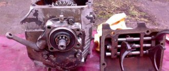
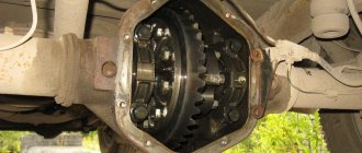
There may be several reasons for increased noise from the front axle while driving. A similar problem occurs if the differential bearings are incorrectly adjusted or simply worn out (Figure 3).
In addition, front axle noise can occur when gears, gear bearings are damaged and worn, or when there is insufficient oil in the axle housing.
Figure 3. Failure of some parts can cause noise
To eliminate this malfunction, first determine the cause of the breakdown. If bearings or gears are worn out, they are simply replaced. If there is an oil leak, first check the front axle crankcase seals, restore the rubber parts and add oil. If problems arise with the gearbox, it is replaced or repaired.
Oil leak
Oil leakage is the most common cause of front axle malfunctions (Figure 4).
The reasons for such a breakdown may be:
- Worn or damaged seal.
- Worn inner joint housing oil seal.
- Loose fastening of the bearing caps of the internal hinge housings or crankcase covers.
- Damage to sealing gaskets.
Figure 4. Oil leakage - another common breakdown
To eliminate damage, simply repair or replace worn parts.
Front axle care
To prevent damage to the front axle during operation of the tractor, the part must be carefully maintained. First of all, maintenance comes down to periodically checking the oil level in the front axle housing, upper bevel pairs and wheel gear housings (Figure 5).
Figure 5. Regular preventive inspection will help avoid breakdowns
It is also necessary to regularly change the lubricant in these parts, periodically tighten the threaded connections and adjust the bearings.
In addition, they regularly check the pressure level in the front tires, wheel alignment and clean the air passages of the breathers. As a rule, these actions are sufficient for the smooth functioning of the tractor’s front axle for many years.
Practical tips for repairing the front axle of the MTZ-82 tractor are given in the video.