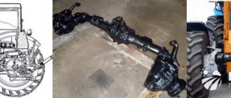
The MTZ 82 all-wheel drive tractor is equipped with an additional transmission part for transmitting torque to the front drive wheels. The drive system includes: transfer case; intermediate support; driven and driven cardan shafts. The intermediate drive support performs the function of transmitting rotation through the drive cardan shaft from the transfer case to the front axle of the tractor through the driven cardan shaft, additionally smoothing out sharp rotational loads with the friction clutch built into its design.
The function of the friction clutch of the unit is to protect the drive shafts and the front axle mechanism from damage that occurs in the event of a sudden start of movement with a large hook load. A particularly significant example is when, when starting, the front wheels have a good coefficient of adhesion on a dry, hard surface, and the rear wheels on a slippery and soft surface. In this situation, the rear wheels slip, and most of the engine power is redistributed to the front drive wheels. At this moment, the clutch friction discs, configured to operate when the force exceeds 400-800 N.m (40-80 kgf.m), partially slip, thus leveling the peak loads on the drive and axle parts.
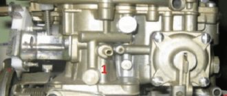
Intermediate support device
Often in practice the described unit is called “promopore” or “suspended support”, “suspended support”, and also in common parlance “piglet”. A separate cast-iron housing of the assembly is attached with a bracket to the lower part of the clutch housing. The mount is installed on two pins 1 and tightened with three fastening bolts. The length of the bolts should not exceed 40 mm, as an increased size can lead to obstruction of rotation of the engine flywheel.
Diagram of the intermediate support MTZ 82
In the support housing 6, on two ball bearings 8 (No. 6015), a connecting tubular sleeve 10 , the internal splines of which connect the drive intermediate drive shaft to the front driven drive shaft through a friction safety clutch. The coupling is a splined shaft 12 13 14 assembled on it , which are installed in pairs. The driving disks 13 with teeth along the inner diameter engage with the splines of the coupling shaft 12 , and the driven disks 14 with external teeth engage with the splines of the connecting sleeve 10 . A set of disks is installed on a spacer sleeve 7 ; on the reverse side, the disks are pressed by spherical spring washers 15 , which create a constant force on the connected disks to transmit rotation. The structure is secured by a coupling nut 2 installed through the mounting flange 3 of the intermediate propeller shaft. The degree of tightening of the nuts regulates the force of the spring washers to press the clutch disks against each other and, accordingly, the actuation force of the clutch. The rotation received from the coupling to the intermediate sleeve is transmitted through a splined connection to the sliding flange 11 connected by a cardan to the FDA main drive.
In a standard situation, the clutch shaft and intermediate sleeve work as one whole part, transmitting rotation without changing frequency to the front drive axle. When sudden loads occur, the disks, reacting to jerks, rotate relative to each other, overcoming the friction force between the disks created by the degree of tightening of the coupling nut 2 . In this case, the shaft rotation speed is not completely transmitted to the intermediate sleeve. In this way, the supplied peak power pulses are damped.
MTZ 82 gear shift diagram
MTZ-80/82 “Belarus” is one of the most popular tractors in the former USSR.
This machine has been produced in Minsk, as well as at a number of other factories in the USSR since 1974 and continues to be produced to this day. Initially, the tractor was developed as a light agricultural machine. However, in our country it has received much wider application. On the basis of MTZ-80/82, a variety of construction equipment was made, such as bulldozers and excavators, which became no less famous than agricultural equipment.
Therefore, information about the operation and maintenance of this tractor will be of interest to the widest public. The article below will discuss in detail the MTZ 82 gearbox, its capabilities, as well as the procedure for switching MTZ 82 speeds.
Causes of support malfunctions
Often, insufficient pressure on the clutch discs provokes operation and slipping at weak forces, which is accompanied by overheating of the unit. The clamping force of the promo-pore cotter pin nut can decrease as a result of natural operating wear of the coupling discs, as well as when the elasticity of the spring disc washers, which exert their force on the coupling discs, decreases. When slipping occurs as a result of friction, the oil boils in the support body and the excess pressure of the expanded heated lubricant squeezes out the sealing seals. After loss of lubrication, the unit begins to run dry, subjecting the structural parts to rapid wear. If the control subsequently ignores the condition of the unit, operation without lubrication can lead to destruction of parts and jamming of the mechanism, as well as emergency breakage of the support housing mounting bracket.
An additional factor influencing the operation of the intermediate support is the reliability of the tightening of the assembly bracket to the tractor clutch housing. Another important factor is the balancing of the drive shafts and the condition of the crosspiece bearings.
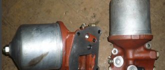
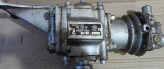
Design of the reverse gearbox MTZ-80 and MTZ-82
A reverse gearbox is located between the clutch housing and the gearbox. This unit is responsible for quickly changing the direction of movement from front to rear.
The reverse gearbox consists of two units: a block of shafts and gears, as well as a gearbox control unit. A drawing of the reverse gearbox can be seen in the figure below:
The numbers in the figure indicate:
Repair and adjustment
If a malfunction in the operation of the support is detected, it is recommended to disable the front axle drive. In compliance with safety regulations, inspect the unit and check the lubricant level in the housing. If there is a working oil level and there are no unacceptable backlashes on the seats of the connecting flanges of the unit, tighten the adjusting nut 2 with a force of 40 N.m (4 kgf.m.) to achieve an increase in the clutch actuation force to 400-800 N.m (40-80 kgf. .m).
Support Clutch Adjusting Nut
If the adjustment does not give a positive effect in the operation of the unit, it is dismantled to inspect the unit and troubleshoot problems. When performing an inspection, if the assembly parts are in normal condition, the reason for the lack of the set clutch actuation force is the wear of the friction discs. Fix the problem by additionally installing a pair of working disks and, if necessary, change the spring disc washers. Thus, the wear thickness of the discs is compensated and the required force when tightening the adjusting nut is restored.
Also, during subsequent repairs, it must be taken into account that due to heating of the oil, rubber seals lose their elasticity and, although visually intact, do not perform their sealing function.
The procedure for assembling the intermediate support
Before starting assembly, make sure that there is no unacceptable wear on the parts' seats. The presence of ellipse in the seating areas of the intermediate sleeve, support sleeve, sliding and connecting flanges will cause imbalance during rotation and will not allow the seals to fit tightly in the assembly structure.
Assembly of intermediate support MTZ 82
The assembly of the unit is carried out in the following order:
- seating the oil seal in the support body
- seating bearings on intermediate sleeve
- fit into the intermediate sleeve of the supporting sleeve of the connecting flange
- Fitting the bushing with bearings into the unit body, assembling the coupling parts onto the shaft
- installing the coupling on the internal splines of the intermediate sleeve
- installing a sliding flange on the intermediate sleeve splines
- installation of seals on the side of the connecting flange
- installing sealing gaskets under the unit covers and tightening them
- adjusting tightening of the coupling cotter pin nut with a force of 40 N.m
When assembling, make sure that the installed parts take their place without distortion.
Assembly procedure for the promo-pore coupling
The sequential installation of parts on the coupling shaft is carried out in the following order:
- installing a spacer sleeve on the shaft
- behind it, a reinforced drive clutch disk and a complete set of clutch disks are installed (alternately leading - driven)
- at the end of the set a reinforced disk is also installed
- then install pairs of spring disc washers
The correct assembly of coupling parts is checked by the presence of a compression effect on the discs when tightening the coupling nut on top of the installed connecting flange.
The number of disks in the coupling can be different and depends on the working thickness of the disks included in the assembly. The set of disks must correspond to a size that allows, in the assembled state, to provide a supply of the threaded part of the shaft shank for the required tightening force.
Controls and instruments
Rice. 3a.
1 — diesel engine stop and emergency stop handle. When you pull the handle toward you, the fuel supply to the cylinders stops and the diesel engine stalls. When released, the handle returns to its original position under the influence of a spring.
2 — control handle for the cabin heater valve (if installed).
3 — differential lock control handle (for tractors with power steering housing); has three provisions:
- I "lock off"
- II "automatic blocking",
- III “forced blocking”.
4 — handwheel for controlling the water radiator shutter. When the handwheel rotates clockwise, the curtain rises; when rotated counterclockwise, it lowers. When the curtain is lowered, the temperature of the diesel engine decreases.
5 — rear axle differential lock pedal. When you press the pedal all the way, the lock is turned on, when you remove your foot from the pedal, it turns off.
6 - switch for starting aids (EFS).
7 — windshield washer switch.
8 - light switch. It has two positions: I — instrument lighting and side lights are on; II - in addition to position I, road headlights are turned on.
9 — alarm switch.
17 - switch for direction indicators, low and high beams, sound signal.
19 — radio receiver (optional).
20 — cover of the steering wheel height adjustment mechanism. To change the height, remove the cover, unscrew the wing nut 3-5 turns and set the required steering wheel height.
21 — front window wiper switch.
22 — cabin heater fan switch.
23 - switch for rear working lights.
24 - front working headlight switch.
24a — switch for the “Road Train” sign.
25 — cabin lamp with switch.
26 — air distributor of the cabin ventilation and heating system.
Rice. 3b.
Important ! Before you start working on the tractor, study the purpose of the controls, instruments and their functions.
27, 28, 29 — hydraulic system distributor control levers: 27 — left side terminals; 28 — right side terminals; 29 - rear terminals. If the tractor does not have a power regulator, then lever 29 controls the cylinder of the hitch, and lever 27 controls the left side and rear outputs duplicated with it.
The connection diagram for the hydraulic system terminals is shown on the instruction plate in the tractor cabin (see Fig. 4.1). Each lever has 4 positions: “floating”, “forced lowering”, “neutral”, “raising”. In the “forced lowering” position with the engine running, the lever should be held by hand.
Rice. 4.1.
30 — tachometer speedometer control panel (see Fig. 9.2).
31 - starter and instrument switch. Has three positions (from neutral):
- I - power supply of devices;
- II - turning on the starter;
- position counterclockwise from neutral - the radio is on.
32 — lever for turning on the reduction gear. It has two positions: front - “Gearbox on” (slow movement of the tractor) and rear - “Gearbox off” (fast movement of the tractor).
In a tractor with a synchronized reduction gearbox, the control lever 32 has two positions: rear - “Gearbox on” (slow movement of the tractor) and front - “Gearbox off” (accelerated movement of the tractor).
In a tractor with a synchronized reverse gearbox, control lever 32a (Fig. 4.1.1) (unlike lever 32 is bent to the left along the tractor) has two positions: rear - “Reverse on” and front - “Reverse off” (forward travel) .
Rice. 4.1.1.
33 — connecting bar of the brake pedals for simultaneous braking with the right and left brakes.
34 — fuel control pedal.
35, 36 — brake pedals. When you press the pedals with your foot, the tractor slows down; at the same time, the brake valve of the pneumatic drive of the trailer brakes is activated from pedal 35. 37 — handle for fixing the tilt of the steering column.
38— clutch control pedal.
39 — gear shift lever. When moving the lever forward in the extreme left position, the 2nd (increased) gear range is switched on, and back - the 1st (lower) gear range. Gear shifting is carried out in accordance with the diagram (Fig. 4.2.).
Rice. 4.2.
40 — control lever for the attachment fixing mechanism. The extreme left position of the lever is “the hitch is fixed”, the extreme right is “the fixation is removed”. You must first raise the hitch to the top position.
41 — control lever for the transfer case of the FDA drive. The middle position of the lever is “FDR is switched on automatically”, lower (pull) – “FDR is switched off”, upper (pull) – “FDR is forcibly switched on”.
42 — parking brake control lever.
43 — lock of the power regulator control handle.
44 — fuel supply control handle. The extreme forward position is the maximum fuel supply, the rearmost position is the minimum supply corresponding to the minimum idle speed.
45 — power regulator control handle. The rearmost position of the handle is “raising the implement” (while lifting, hold the handle with your hand); after releasing the handle, it moves forward and is fixed in the “transport neutral” position. The intermediate position forward from the “transport neutral” position is the “regulatory zone”. The extreme forward position of the handle is “forced lowering” (hold the handle with your hand). After releasing the handle, it returns back and is fixed at the leading edge of the control zone.
46 — rear PTO control lever.
It has two positions: front - “PTO off”, rear - “PTO on”.
47 - battery ground switch.
48 — seat backrest tilt lock.
49 — seat belt bolt
Node maintenance
Intermediate support maintenance measures:
- Check the presence of lubricant in the housing at the level of the inspection hole, as well as the lubrication of the cardan joints of the drive every 120 hours of operation
- Check that the assembly is securely tightened
- Check the reliability of the connection of the flanges of the drive shafts with the transfer case, suspension support and final drive of the front axle
- Pay attention to the appearance of lateral play in the bearings of the crosspieces. Timely replacement of crosspiece bearings will prevent serious damage to the drive.
- Based on the nature of the work performed using the front drive axle, pay attention to the moment the support clutch is activated. If necessary, tighten the coupling nut.
The filling volume of the unit is 0.15 liters. The transmission lubricant used for the support is TAp-15V, TSp-10, TSp-15K, TAD-17 GOST 2365-79. For the convenience of filling the unit with lubricant, many practitioners additionally equip the body with a grease dispenser with a spring-loaded shut-off ball valve.
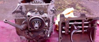
Gearbox design MTZ-80 and MTZ-82
The MTZ-80/82 gearbox is a cast-iron crankcase containing 4 shafts on which gears are mounted. The main shafts are the primary and secondary, which are located one above the other. When generating torque, they are helped by two other shafts - intermediate and additional.
All gearbox shafts rest on bearings located in the walls of the box housing, as well as in the central partition.
The gearbox housing itself is filled with transmission oil, which provides lubrication of the rubbing surfaces. To prevent oil from leaving the crankcase, there are seals at the ends of the shafts.
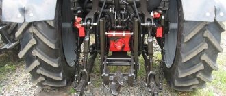
Repair of the front drive axle MTZ-82
We will consider the repair in several stages depending on those symptoms. Which can be observed. Each stage will be illustrated with detailed pictures.
If traces of grease appear on the propeller shaft flange and the main gear housing, this is the first sign that elasticity will be lost and the main gear cuff will collapse. To do this, replace the cuffs and disconnect the driveshaft. First, unscrew the castle nut and remove the cardan flange. Next, unscrew the bolts securing the main gear cup bearings and two mounting bolts. Afterwards, the drive gear is pressed into the glass and the assembly with the cuff itself is removed.
If traces of oil are found on the inner surface of the wheel rim or on the disk flange, this is a sign that the wheel axle is damaged. To do this, you need to remove the wheel and the final drive gearbox as a complete assembly (see the diagram of the arrangement of parts for the final drive gearbox of the MTZ-82 tractor).
then you need to unscrew the two radial bearing securing bolts and remove the driven gear.
So we looked at the main problems of the front axle of the MTZ-82 tractor. We hope that this article was useful to you.