_______________________________________________________________________________
Drive axles of the Kamaz-4310 vehicle
Rear axle of Kamaz-4310
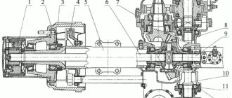
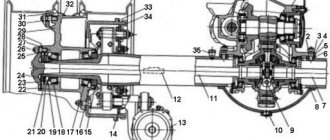
Fig.1. Rear axle KamAZ-4310 1 — locknut, 2 — wheel stud; 3 - hub; 4 — shield; 5 - fitting; 6, 11 — breathers; 7.9 — oil seals; 8 cover of the air supply seal block; 10 — spring bracket; 12 - axle shaft; 13 — brake chamber; 14 - flange; 15 — expansion fist bracket; 16- block of air supply seals; 17 - axle; 18 — brake support disk; 19, 20 — tapered bearings; 21 — brake drum; 22 - nut; 23 — lock washer; 24 - tire tap; 25 — thrust bracket; 26 — axle housing The Kamaz-4310 drive axles have double main gears, one pair of bevel gears with spiral teeth, the second pair of cylindrical helical gears; the overall gear ratio is 7.62. The design of the main gears of all three KamAZ-4310 axles is the same, however, the assembled main gears of the front, intermediate and rear axles are not interchangeable. The main parts of the Kamaz-4310 main gear (Fig. 2) are: crankcase 1, drive shaft 22 with bearings, drive bevel gear 21, driven bevel gear 2, drive spur gear 3 with shaft and bearings, driven spur gear 14.
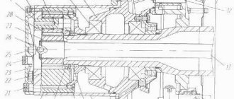
Fig.2. Main gear and differential of the rear axle gearbox KamAZ-4310 1 - crankcase; 2 — driven bevel gear; 3 — driving cylindrical gear; 4, 6, 10, 18, 20 — tapered roller bearings; 5 - cup of bearings; 7, 19 - adjusting washer; 8, 17 — shims; 9 — adjusting nut; 11 — differential cup; 12 — cross; 13 — semi-axial gear; 14 — driven cylindrical gear; 15 - roller bearing; 16 — gasket; 21 — driving bevel gear; 22 - drive shaft; 23 — bearing cover; 24 - stopper. The intermediate and rear axle housing of KamAZ-4310 is attached to the bridge beam with a horizontal flange using studs located on the outside. There are grooves on the inner walls of the crankcase, and in the walls there are channels for the passage of oil to the bearings. There is a filler plug on top of the crankcase; the control and drain plugs are located on the axle crankcase. The drive shaft 22, together with the drive bevel gear 21 mounted on its splines, rotates in the crankcase on two bevel bearings 18 and 20 and one cylindrical roller bearing. The front tapered bearing 18 is located in the cup, the rear bearing 20 is installed in the crankcase bore. With inner rings, bearings 18 and 20 are pressed onto the shank of drive gear 21. A flange is installed on shaft 22 for connecting the cardan drive; the shaft exit from the crankcase is sealed with a rubber cuff and an oil deflector. The driven bevel gear 2 is mounted on a shaft manufactured integrally with the driving cylindrical gear 3. The supports of this shaft are two tapered bearings 4 and 6 located in the cup, and a cylindrical roller bearing 15 installed in the crankcase boss. The driven spur gear 14 is attached to the differential cups with bolts. The main gear of the Kamaz-4310 intermediate axle has a through drive shaft; flanges are installed at both ends for connecting cardan shafts. The main gear of the Kamaz-4310 front axle gearbox is attached to the bridge beam with a flange located in a vertical plane; the drive shaft here is non-passing and its inner end rests on a cylindrical roller bearing located inside the crankcase. When the drive shaft rotates, torque is transmitted from the drive bevel gear to the driven gear, then to shaft 4 and the drive spur gear, from where through the gearing to the driven spur gear and differential. In a bevel gear pair, the torque changes in magnitude and direction, while a cylindrical gear pair changes the torque only in magnitude. Lubrication of the main gear of the Kamaz-4310 drive axle gearbox is carried out by splashing. The Kamaz-4310 intermediate and rear axle crankcases are filled with 7 liters each, and the front axle crankcase is filled with 4.8 liters of oil. Adjusting the main gear of the KamAZ-4310 axle gearbox It is not recommended to disassemble and adjust the main gear of the KamAZ-4310 rear axle gearbox unless necessary. Bevel gears must be operated until they are completely worn out. If during operation the lateral clearance in the meshing of the bevel gears increases, adjustment should not be made, since this will disrupt the correct meshing of the bevel gears. If the increase in the lateral clearance in the meshing of the bevel gears is a consequence of wear of the tapered roller bearings, i.e. If an axial gap appears in the engagement, then the tapered bearings are adjusted. The bearings are adjusted when the main gear of the KamAZ-4310 gearbox is removed from the bridge and disassembled into components. Tapered bearings are adjusted with a slight preload; axial play is not allowed in them. Adjustment of the tapered bearings of the KamAZ-4310 drive cylindrical gear is carried out by selecting the thickness of two washers 19 installed between the inner rings of the bearings. The correctness of the adjustment is checked by the amount of torque required to rotate the shaft in the bearings. This value should be in the range of 0.8... 1.6 N. Adjustment of the tapered bearings of the Kamaz-4310 drive spur gear shaft is carried out by selecting the thickness of two washers 7 installed between the inner rings of these bearings. The torque required to rotate the shaft of the drive spur gear after adjustment should be 1.0...3.5 N. After adjusting the preload of the bearings, the Kamaz-4310 main drive units are installed in the crankcase and the lateral clearance and contact patch of the bevel pair are adjusted. The lateral clearance equal to 0.2...0.35 mm and the contact patch between the teeth of the bevel gears are regulated by selecting the thickness of the gasket package 8 and 17, installed under the bevel bearing cups. To check the correct engagement along the contact patch, the teeth of the drive gear are painted and turned by hand in both directions while simultaneously braking the driven gear by hand. The stain remaining on the teeth of a heavy gear should have a length equal to approximately 2/3 of the length of the tooth and be located in the middle part of the tooth. The driving and driven bevel gears are selected into sets at the factory, ground in and branded, indicating the serial number of the set. Therefore, disassembly of these parts is not permitted. Differential of the KamAZ-4310 drive axle The differentials of all three KamAZ-4310 axles are conical, symmetrical, and are installed in the main gear housings on two tapered bearings each. The differential of Kamaz-4310 axles consists of two cups 11, a cross 12, four satellites with support washers, two semi-axial gears 13 with washers. The differential cups are connected to each other and to the driven spur gear to form the differential housing. The crosspiece has four spikes with which it is clamped between the cups; The flats on the crosspiece tenons serve to allow oil to pass through. The satellites are bevel gears mounted on the spikes of the spider. A bronze bushing is pressed into the satellite hole. A spherical support washer is installed between the Kamaz-4310 differential housing and the back part of the satellite. The semi-axial gears are placed in cups with their hubs and are connected to the axle shafts by splines. Flat support washers are installed between the cups and the semi-axial gears. Each side gear is in constant mesh with all four satellites. The operation of the differential of the KamAZ-4310 bridge is as follows. When a car moves straight on a level road, the wheels of one axle travel the same paths and, therefore, rotate at the same angular speed. All parts of the differential of the KamAZ-4310 axle rotate around a common axis at the same speed as the wheels; the satellites do not rotate around the axes. Torque is transmitted from the driven spur gear to the differential cups, then to the spider and satellites, which with their teeth act with equal force on the teeth of the side gears, causing them to rotate. Since the radii of the side gears are the same, the torque on the side gears will be the same. Thus, the torque between the wheels of the differential is distributed equally, which is why it is called symmetrical. When turning a corner, for example, to the left, the right wheels travel a longer distance than the left ones, therefore, they must rotate faster than the left ones. The Kamaz-4310 axle differential provides this opportunity. In this case, all differential parts rotate around a common axis and at the same time the satellites rotate around their axes, slowing down the rotation of the left side gear and accelerating the rotation of the right side gear. In this case, as much as the rotation of the left wheels slows down, the speed of rotation of the right wheels increases. If we neglect the internal friction in the differential (and it is insignificant), then the torque in this case is distributed equally. When a Kamaz-4310 vehicle slips, one wheel hits a slippery road. Due to poor traction, this wheel begins to slip and rotate faster than the second wheel. The differential contributes to this. When the left wheel is completely stopped, for example, the right wheel rotates twice as fast as the differential cups. To rotate a slipping wheel on a slippery road, a slight torque is required due to the differential’s ability to distribute torque equally; the second non-slip wheel receives the same insignificant torque. A non-slipping wheel is not able to develop the necessary traction force, move the car and continue moving. Thus, when driving on slippery roads, the differential reduces the vehicle's maneuverability. The KamAZ-4310 differential bearings are adjusted with a slight preload using nuts 24. The correctness of the adjustment is checked by the amount of deformation of the crankcase when tightening the adjusting nuts. Pre-tighten the bolts securing the 23 bearing caps to a torque of 100...120 N, then by tightening the adjusting nuts, ensure such a tension in the bearings that the distance between the ends of the bearing caps increases by 0.1...0.15 mm. Axle shafts and beams of KamAZ-4310 bridges KamAZ-4310 axle shafts are completely unloaded, i.e. transmit only torque and do not perceive vertical, longitudinal and transverse forces. The axle shafts are located in the casings of the bridge beams (Fig. 1). The inner end of the Kamaz-4310 axle shaft has splines with which it is connected to the differential side gear, the outer end ends with a flange with which the axle shaft is attached to the wheel hub 3 using studs and nuts. To center the axle shaft relative to the hub, split conical bushings are installed in the flange holes. The KamAZ-4310 axle shaft has a neck for installing a seal block 16 for supplying air to the tire, as well as radial and axial drilling for the passage of air to the tire valve 24. The exit of the axle shaft from the bridge beam is sealed with an oil seal 9. Kamaz-4310 bridge beams are used to transfer the weight of the sprung part to the wheels and transmission from the wheels to the frame of longitudinal, transverse and vertical forces. On Kamaz-4310 vehicles, the beams are stamped and welded. The front axle housing of the Kamaz-4310 vehicle is molded integrally with the left short casing, the right casing is pressed into the crankcase and is held in place by rivet welding. At the ends of the beams of the rear and intermediate axles of KamAZ-4310, round flanges 14 are welded (see Fig. 1) for attaching the wheel axles. Brackets for attaching rear suspension parts are welded to the axle housings of the same axles of all three cars. The housings of the axle shafts of the front axles of KamAZ-4310 end with round flanges, to which the ball joints of the steering knuckles are attached. Front axle KamAZ-4310
Fig.3. Front axle of the KamAZ-4310 1 - outer hinge fork; 2 — tire tap; 3 - axle; 4 — air supply fitting; 5 — steering knuckle body; b — adjusting shims; 7 — steering knuckle lever; 8 — ball joint; 9 - internal hinge fork; 10 - plug; 11 — bottom cover; 12 — hinge fist; 13 — disk; 14, 19, 20 — bearings; 15 — brake guard; 16 — brake support disk; 17 — pad axis; 18 — oil seal; 21 — hub; 22 — centering sleeve; 23 — cylinder flange; 11 — brake drum; 12 — tube for supplying air to the tires; 13 — axle shaft; 14 — spring bracket. The Kamaz-4310 steering knuckle provides the ability to turn the front steered wheels. It consists of a ball joint 8 and (Fig. 3) a housing with two covers (top and bottom), a pivot pin 3, fastening parts and seals. The ball joint is installed in the beam of the KamAZ-4310 bridge and is attached to it with pins; two kingpins are pressed and welded into its spherical surface. The Kamaz-4310 steering knuckle body is mounted on kingpins on tapered bearings. The lower bearing is closed by a cover 11, the upper bearing cover is integral with the swing arm 7. Adjusting shims are installed between the steering knuckle housing and the covers. Trunnion 6 is attached to the steering knuckle body with pins together with the support disk 16 of the brake mechanism. In the recess of the axle there is a block of air supply seals, and there are also holes for the passage of air to the tire valve 2. The tapered bearings of the Kamaz-4310 king pins are lubricated with the lubricant that is placed inside the ball joint to lubricate the constant velocity joint. Adding grease is done through the grease nipple in the upper bearing cover; the lubricant must be in a heated state, and the lubricant is replenished until it flows through the hole closed by plug 10. The lubricant is retained and prevented from contaminating the internal cavity of the Kamaz-4310 steering knuckle by a rubber cuff and a felt ring enclosed in metal clips. Adjustment of the tapered bearings of the Kamaz-4310 steering knuckle is carried out by preload; axial play in the bearings is not allowed. Adjustment of Kamaz-4310 bearings is carried out by removing the gaskets from under the upper and lower covers. Correct adjustment is checked using a dynamometer based on the force required to turn the fist. This force should be 20...30N. When checking, the bearings should be lubricated, the axle shaft removed, the bearing cap nuts tightened, and the steering knuckle seals removed. The pivots are installed in a ball joint with an inclination of 6° in the transverse plane and 1°45 in the longitudinal plane of the vehicle. This installation of pins increases the stability of the vehicle and helps it maintain the given direction of movement. Constant velocity joints (CV joints) Kamaz-4310 Constant velocity joints (CV joints) Kamaz-4310 are cam-type, installed in the drive on the front steered wheels, located inside the steering knuckles (see Fig. 4) of the front axle. The Kamaz-4310 CV joint consists of two forks 1 and 5, two knuckles 2 and 4 and a disk 3. When turning and rotating the wheel, the knuckles rotate relative to the forks and at the same time relative to the disk, which ensures the transmission of rotation from the inner fork to the outer one at the same angular speed. Fig.4. Constant velocity joints (CV joints) KamAZ-4310 a - cam; b - ball: 1 - outer plug; 2,4,6,7 - fists; 3 — disk; 5 - inner plug; 8 — driving balls; 9 - centering ball. Lubrication of the Kamaz-4310 CV joint is provided by oil poured into the steering knuckle housing. 3.0 liters of a mixture of Litol-24 lubricant and TSp-15K oil (50% each) is placed into the cavity of each hinge.
_______________________________________________________________________________
_______________________________________________________________________________
_______________________________________________________________________________
- Clutch KamAZ-5320 and its components
- Repair of PGU and Kamaz clutch master cylinder
- Gearbox gearbox KamAZ 141
- Gearbox gearbox KamAZ ZF 16
- Gearbox 152 Kamaz with divider
- Gearbox gearbox 154 Kamaz
- Gearbox Kamaz-4308
- Clutch of a Kamaz-4308 car
- Clutch and gearbox KamAZ-65115
- Disassembly and assembly of Kamaz-4310, 55111, 43118 gearboxes
_______________________________________________________________________________
- Cylinder block, head and valves Kamaz-740
- Fuel system of Kamaz-740 diesel engine
- Adjustments and repairs of fuel injection pump Kamaz-740
- Drive axles of the Kamaz-4310 vehicle
- Repair of Kamaz drive axle gearbox
- Rear axle KamAZ-4308
- Axles and suspensions of Kamaz-65115 dump trucks
- Installation of Kamaz cardan shafts and axles
- Repair of Kamaz vehicle transfer case
- Kamaz power steering - adjustments and repairs
- Repair of Kamaz steering gear parts
- Steering parts Kamaz-4308
- Parts of the brake system Kamaz-4308
- Brake system and brake drive Kamaz
- Repair of brake valves and Kamaz compressor
- Suspension Kamaz-4310, 55111, 43118 and their parts
- Frame and suspension of the Kamaz-4308 car
- Cabin details and platform KamAZ-65115
- Cabin components Kamaz-4308
- Platform mechanism of Kamaz vehicles
- Klintsy KS 65719-5K truck crane based on KamAZ-6522 chassis
- Truck crane KC-35719-7-02 based on Kamaz-43118 chassis
- Truck crane Galichanin KC-55713-1K based on KamAZ-65115 6x4
- Ivanovets KS-45717K-1/1R truck crane based on KamAZ-65115 chassis
- Ivanovets KS-3577-3/4 truck crane on KamAZ-43253 4x2 chassis
Gearbox KAMAZ 4310 rear axle
The KAMAZ 4310 rear axle gearbox is a mechanism used to transmit torque from the crankshaft to the wheels. In some catalogs it is also called “KAMAZ main gear”. During operation, the KAMAZ 4310 gearbox is subject to heavy loads, because this vehicle is considered an army vehicle, which means it must travel over rough terrain, in the mountains and in the sand. It is not surprising that after such tests the rear axle gearbox of the KAMAZ 4310 fails.
Gearbox KAMAZ 4310 price 2016 - located in the price list section.
Catalog
| Name | vendor code |
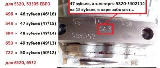
| Gearbox KAMAZ 4310 rear axle 48 teeth | 5320-2402010-30 |
| Gearbox KAMAZ 4310 rear axle 49 teeth | 5320-2402010-10 |
| Gearbox KAMAZ 4310 zadengo axle 50 teeth | 5320-2402010-20 |
KAMAZ 4310 rear axle gearbox - causes of malfunctions
With proper use, this unit can serve for a long time. But not all drivers pay due attention to it. The main causes of malfunctions due to which the KAMAZ 4310 rear axle gearbox fails are: - excessive loads; — incorrect installation of mechanisms on axles (for example, the middle one has 49 teeth, and the rear one has 48); - improper maintenance.
Sometimes drivers forget to change the oil on time or use the wrong lubricant, as a result the KAMAZ 4310 rear axle gearbox fails ahead of time. Driving at speed with the lock on is also a cause of breakdown.
What kind of oil should be poured into the rear axle gearbox of KAMAZ 4310
Today there are many high-quality transmission lubricants, both domestic and imported. The most popular domestic product is mineral gear oil TAD-17, which has good technical characteristics. Thanks to highly effective additives, the lubricant creates a dense film on rubbing surfaces, which makes it possible to use the transmission in extreme conditions at temperatures from -35 to +50 degrees.
As for foreign manufacturers, it is best to fill the KAMAZ 4310 gearbox with gear oil of well-known brands: Castrol, Mobil, Shell with a viscosity of 80W-90 or 75W-90. Of course, it is preferable to domestic, but somewhat more expensive.
Free delivery to Russian cities: Smolensk, Yakhroma, Reutov, Podolsk, Serpukhov, Voronezh, Elektrostal, Lipetsk, Khimki, Dubna, Kaluga. Tver, Bryansk, Ramenskoye, Korolev, Solnechnogorsk, Zaraysk, Krasnogorsk. Vereya, Sergiev Posad, Losino-Petrovsky, Mytishchi, Zhukovsky, Kurovskoye, Shatura, Ruza, Tula, Klin and many others in the central part of the Russian Federation.
You can buy a KAMAZ 4310 gearbox from the sales department by calling (495) 740-08-48