Classification and designation of tank trucks
Tank trucks (tank vehicles and tank road trains) are vehicles used for the transportation and temporary storage of liquid, semi-liquid, gaseous, powdery and bulk cargo.
Tanker trucks (AT) also include tanker trucks designed for transporting petroleum products and refueling transport equipment with them.
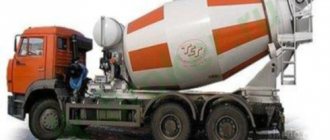
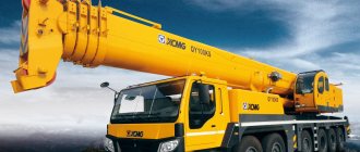
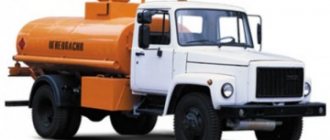
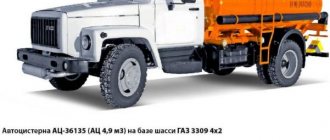
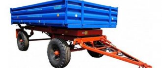
Tanks (tank truck tanks) are installed on the chassis of trucks, trailers and semi-trailers (Fig. 1). Tank trailers (Fig. 2) and tank semi-trailers (Fig. 3) are aggregated with tractors. In this regard, a distinction is made between tank cars (Fig. 4) and tank road trains (Fig. 5).
Figure 1 – Tanks installed on the chassis of trucks and trailers
Figure 2 – Tank trailer
Figure 3 – Tank semi-trailers
Figure 4 – Tank vehicle
Figure 5 – Tank road trains
Tank trucks are classified according to the following criteria (Fig. 6):
- a) by type of base chassis - tank car, tank trailer, tank semi-trailer;
- b) according to cross-country ability - normal, increased and high cross-country ability;
- c) for its intended purpose - for transportation, for transportation and refueling;
- d) by type of cargo being transported (refueled) - for liquid, gaseous, powdery, bulk and semi-liquid cargo;
- e) by class – class 1 – for explosives; 2 – for liquefied and compressed gases, as well as those dissolved under pressure; 3 – for flammable liquids; 4 – for flammable substances and materials;
- f) by capacity (carrying capacity) of the tank - small, medium and large capacity;
- g) by type of supporting system - frame (the tank is mounted on a frame) and load-bearing (suspensions and wheels are attached to the tank);
- h) by type of technological equipment for unloading the product - under the influence of gravitational forces (gravity flow and pouring), mechanical unloading, pneumatic unloading, unloading using pumps (our own or third-party), dump truck unloading.
Figure 6 – Classification of tank vehicles
When designing an AC, the properties of the transported product are taken into account: density, saturated vapor pressure, electrification, corrosion, toxicity, etc.
Additional requirements for tank trucks:
- muffler outlet forward and to the right outside the tank area with the outlet tilted down;
- protection of the fuel tank from the muffler side: at the front with a screen (metal shields) and at the bottom with a metal mesh with a mesh size of 10x10 mm (at a distance of at least 20 mm);
- additional fuses must be installed in the electrical circuits; the battery ground switch (if available) must be located in the driver’s cab;
- lighting lamps with protective grilles;
- electrical wiring is laid in tubes;
- grounding the AC with a metal circuit;
- the presence of two fire extinguishers outside the cabin;
- hazard information system (inscriptions, flashing lights), etc.
The designation of tank trucks consists of a series of letters and numbers.
The letters indicate the type of base chassis (A – car, P – trailer, PP – semi-trailer) and the purpose of the tank (C – transport tank, TZ – fuel tank).
The numbers indicate the nominal capacity of the tank in cubic meters and the brand of chassis.
Along with the letters C and TZ, the following designations are used:
- TsZ – refueling tank,
- MZ - oil filler,
- TMZ is a fuel and oil tanker.
Special designations for the type of cargo transported:
- M - oil,
- B – water,
- C – alcohol,
- SF – special liquids.
For example, ATMZ-4.5-375: a fuel and oil tanker, with a main fuel tank with a capacity of 4.5 m3, on the chassis of a Ural-375 vehicle; ATs-4.2-53A – transport tank vehicle, with a capacity of 4.2 m3, on the chassis of a GAZ-53A vehicle; ZSZH-66 is a tanker with special liquids on the chassis of the GAZ-66 car.
Requirements for tractors
The semi-trailer is unable to move independently. This also applies to oil tankers. Any tanker requires a tractor unit. However, there are a number of requirements for transporting flammable goods to tractors.
The location of the exhaust pipe in a gas carrier.
The exhaust pipe must be mounted either on the front right or behind the cab on the right. To avoid emergency situations, a spark arrestor is attached to the pipe.
Construction of tanks and their equipment
Tanks (tank truck tanks) have different shapes, designs and materials, which depend on the type of cargo being transported and its properties. Tanks are usually made of welded sheet steel (low-carbon, corrosion-resistant). In this case, tanks made of low-carbon steel can have an internal anti-corrosion coating made of enamel, lead, zinc, plastic, epoxy resins and other materials. Tanks can also be made of aluminum alloys or plastics reinforced with fiberglass inside.
According to their design characteristics, tanker tanks are distinguished (Fig. 7):
- cross-sectional shape - round, elliptical and rectangular (suitcase type);
- according to the shape of the longitudinal section - constant section and variable section (reduced in the front, middle or rear);
- by the presence of compartments and breakwaters - with one compartment, with an additional compartment, with several compartments, without breakwaters, with one or more breakwaters;
- according to thermal insulation characteristics - without thermal insulation, with thermal insulation (thermal insulation), with additional heating or self-heating;
- by type of material - ordinary steel, high-strength steel without internal coating or with special coating of internal surfaces (enamel, lead, zinc, epoxy film), stainless steel, fiberglass reinforced plastic, etc.
Figure 7 – Classification of tank tanks
The location of tanks (reservoirs) on the chassis of cars, trailers and semi-trailers is also different. Tanks are installed horizontally, inclined and vertically. The vertical and inclined arrangement of tanks is used for the transportation of bulk cargo in order to speed up the unloading process by using the cargo’s own weight. The horizontal arrangement of tanks is used for transporting liquid and gaseous cargo. Vertical tanks have the shape of a cylinder or ball with a lower part in the form of a truncated cone.
Inclined and horizontal tanks usually have a circular or elliptical cross-section, and sometimes rectangular. With inclined and especially vertical tanks, their stability is reduced due to the high center of gravity. To increase the stability of tank trucks when transporting the same mass of cargo, not one, but two or more vertical tanks are used, thereby reducing their center of gravity.
The design of tanks and their equipment significantly depend on the type and properties of the cargo being transported. Some cargo (tar, asphalt, bitumen, liquid sulfur, etc.) when transported in tanks must maintain a certain temperature (for example, liquid sulfur - 140... 150 ° C). Therefore, tanks for transporting such goods are equipped with a special heating system.
Tanks for the transportation of liquid cargo are usually partitioned inside with a number of special partitions in order to reduce the hydraulic shock of the liquid against the walls and bottom of the tank during movement. Tanks for transporting flammable liquids are equipped with fire-fighting devices, and their filler necks are equipped with flame arresters, breathing valves, etc. Special equipment is used to fill and unload tanks. Filling of tanks is usually carried out by stationary equipment located at loading points. Unloading of tanks is carried out by equipment installed on tank trucks.
Manufacturers
Since semi-trailers are in great demand, hundreds of companies produce them. Let's look at those that are more common in Russia.
Kassbohrer
The European brand offers tanks of various modifications, consisting of 4 and 6 compartments. The equipment has increased cross-country ability, which will be a big advantage for rural areas or roads of poor quality.
Sespel
Russian manufacturer presenting a large selection of tanks with a volume of 13.6–36 m³ or more. The company also produces bitumen tankers with a volume of 20 to 38 cubic meters. The trailers have good maneuverability, which allows you to feel confident on the road.
Detailed instructions can be seen in the video:
NefAZ
The steel tanks of the NefAZ plant have a volume of 10–16 cubic meters and are divided into 2 or 3 compartments. The semi-trailers are mounted on a KamAZ chassis; the maximum speed of this duo is 80 kilometers per hour. The prices are reasonable. For many years NefAZ has been included in the all-Russian OKOF classifier. Representatives of the company in dozens of cities across the country are ready to advise and help you lease equipment.
Other manufacturers
We invite you to pay attention to a number of companies that have gained an excellent reputation. The Turkish company Nursan, exporting products to 35 countries around the world, offers a huge range of semi-trailers and fuel tankers. The thickness of the tank walls is never less than 4 mm.
At the customer's request, workers can equip each compartment of the barrel with pneumatic bottom valves. By the way, the company’s prices are very affordable.
GrAZ: One of the oldest enterprises in Russia, which began its journey during the Second World War. The plant produces dozens of semi-trailers that have found recognition in the CIS countries and abroad. There are several options for fuel tankers in the model range. The 15 cc tank is in great demand, but if necessary, they will help you choose a tank that meets your personal requirements.
Semi-trailer for petroleum products from the FoxTank company.
FoxTank: The plant produces tank trucks of European quality. The equipment is adapted to Russian realities. Represented by the widest model range. The capacity of the tanks is from 1.2 to 45 cubic meters.
Bonum: Another local company that is one of the three famous manufacturers of container-filling equipment in Russia. The Bonum plant has repeatedly received honorary awards in thematic competitions and exhibitions, and the company’s catalog is replete with semi-trailers for various needs.
Tankers for transporting petroleum products
Tankers for transporting petroleum products are used to transport low-viscosity light (gasoline, diesel fuel, kerosene, etc.) and viscous (oils, fuel oil, tar, bitumen, asphalt, etc.) petroleum products and dispense them at points of consumption (Fig. 8).
A tank truck for transporting light petroleum products consists of a base truck chassis (Fig. 9.), on which a tank is installed (Fig. 10), which has a neck for filling and compensating for the thermal expansion of the petroleum product, a breathing valve, a filling limiter, a sump with a water separator, oil product level indicator, breakwaters.
Figure 8 – Tankers for transporting petroleum products
Figure 9 – Construction of a tank truck for transporting light petroleum products: 1 – tank V=4.9 m3; 2 – compartment with equipment and control circuit; 3 – neck for fuel expansion (2%); 4 – filler neck with a diameter of 300 mm; 5 – breathing valve; 6 – measuring ruler; 7 – measuring glass; 8 – service platform; 9 – stairs; 10 – sand box; 11 – bracket for fire extinguisher; 12 – bracket for tables indicating the fuel grade; 13 – pump SCL-00; 14 – suction pipeline; 15 – pressure pipeline; 16 – cardan shaft; 17 – cases for hoses; 18 – mudguards; 19 – flashing light; 20 – tool box with grounding wedge; 21 – grounding cord socket; 22 – grounding circuit; 23 – GAZ-3307 chassis
Figure 10 – Tank for transportation of petroleum products: 1 – tank; 2 – pipe; 3, 6 – covers; 4 – square; 5 – bracket; 7 – valve; 8 – float; 9 – neck; 10 – footrest; 11– tube; 12 – cabinet; 13, 14, 16 – pipelines; 15 – breakwater; 17, 19 – supports; 18 – oil product level indicator
Tankers are equipped with pumps for filling, draining and pumping oil products, which are driven by the vehicle engine through a power take-off and driveline, as well as filters, meters, pipelines and hoses (sleeves). Tanks are calibrated and their volume is indicated on a calibration plate fixed inside the neck.
Tanks for transporting fuel are made of carbon steel and coated with zinc on the inside. Their cross section is usually elliptical in shape.
Brief information about the technological equipment of tanks for transporting petroleum products:
- Filling limiter - the float, when floating up, closes the electrical circuit through sealed contacts, blocking access to the oil product into the tank; or the float, floating up, moves the power take-off shut-off spool, and therefore the pump drive.
- The breathing valve is similar in principle to the steam-air valve of a liquid radiator of a car and serves to reduce the loss of petroleum product vapors.
- The settling tank is designed to collect produced water and is equipped with a float with a density lower than that of water, but higher than that of an oil product. Thus, the float sinks in pure oil product, and floats in accumulated water and blocks the entrance to the suction pipeline located above it.
- Pipeline fittings are made of steel or aluminum tubes connecting components and assemblies of technological equipment, ensuring the performance of the above operations.
- A coarse filter (mesh) is installed in the suction pipeline, and a fine filter and a counter for measuring the amount of petroleum product dispensed are installed in the pressure pipeline. The dispensing hoses are equipped with dispensing taps, and the remaining hoses are equipped with quick-release connections with plugs.
- Float type level gauge. The float, floating up, turns the axis with the arrow. The level gauge is designed to approximately determine the filling of a tank with petroleum product.
- Breakwaters are designed to prevent rapid movement of the mass of petroleum product along the tank when partially filled. Otherwise, hydraulic shocks to the bottom and a sharp shift in the center of gravity of the tanker are possible. Breakwaters are wavy (for rigidity) partitions with holes, made up of several canvases (sheets). The breakwaters are attached vertically, across the tank, to reinforcement rings welded from the inside, made from angle iron.
- Flexible pipelines (sleeves) are laid in canisters or cabinets welded to the right and left of the tank. The dispensing hoses of some tank trucks are wound onto a drum.
- Pumps on tanker trucks are typically self-priming (do not require priming before pumping). To pump fuel, centrifugal (with an additional vortex wheel to ensure self-priming) and vortex pumps are used. For pumping oils - gear. When operating gear (displacement) pumps, it must be remembered that they are capable of developing high pressure (pressure), limited only by the drive power and the strength of the parts. Therefore, it is very important to monitor the serviceability and operation of the pressure relief valve and turn on the pump only when the pressure line valve is open.
Tank trailer PC-6.7-8925 (Fig. 11, 12) is designed for transportation of fuel with a density of no more than 860 kg/m3 and its short-term storage. The tank trailer is towed by tank trucks AC-8.5-255B, AC-8-500A and tanker truck TZ-8-255B.
Figure 11 – Tank trailer PC-6.7-8925: 1 – hose mounting support; 2 – trailer drawbar; 3 – pipeline for receiving and dispensing petroleum products; 4 – valve box Du-70; 5 – fire extinguisher; 6 – float level indicator; 7 – tank; 8 – neck; 9 – breathing valve; 10 – filling limiter; 11 – side drawer; 12 – grounding wedge; 13 – grounding device; 14 – pencil case for sleeve; 15 – chassis; 16 – sludge drain pipeline; 17 – grounding circuit
Figure 12 – Diagram of the technological equipment of the tank trailer PC-6.7-8925: 1 – tank; 2 – filler neck; 3 – breathing valve; 4 – filling limit valve; 5 – manual control valve; 6 – receiver for compressed air; 7 – sound signal; 8 – permanent docking fitting; 9, 13 – valves; 10 – filling fitting; 11 – pneumatic hydraulic valve; 12 – settling tank; 14 – drain pipe fitting; 15 – float
Fuel tanker trucks are used to transport light petroleum products and refuel other vehicles with them (Fig. 13).
Figure 13 – Refueling vehicle: a – general view; b – diagram: 1 – car engine; 2 – car cabin; 3 – tank; 4 – pipeline; 5 – control cabin; 6 – control and measuring instruments; 7 – frame; 8 – filter; 9 – pump; 10 – cardan transmission; 11 – power take-off; 12 – muffler
Tankers for transporting agricultural goods
Tankers for transporting agricultural products. cargoes are intended for transportation of liquid food products, liquid mineral fertilizers and bulk cargo.
Tankers for transporting liquid food products (drinking water, milk, kvass, beer, wine, alcohol, fruit juices, etc.) are made of corrosion-resistant steel, aluminum alloys or plastics and have a round, elliptical or rectangular cross-section (Fig. 14) . To make cleaning easier, the inner corners of the tanks are rounded and the surface is polished. At the same time, metal tanks are equipped with thermal insulation. To fill tanks with food liquid and drain it, vacuum devices are used that use vacuum in the inlet pipe of a car engine, as well as autonomous and stationary pumps.
Figure 14 – Tankers for transporting liquid food products
Tanker trucks for transporting milk (Fig. 15) are used to deliver it from procurement points to dairies and factories. To reduce milk agitation, the tank is divided into several individual sections. To ensure the safety of milk, thermal insulation with a thickness of 50-100 mm (foam plastic, polyurethane foam, etc.) is installed. Tanks (reservoirs) usually consist of two or three separate tanks (sections) enclosed in a common casing.
Figure 15 – Tanks for transporting milk: a – tank truck; b – tank trailer; c – diagram of the tank and equipment: 1 – engine pipeline; 2, 8, 16 – taps; 3, 5, 12 – valves; 4 – foam trap; 6 – pressure gauge; 7, 15 – pipelines; 9 – signaling device; 10 – reservoir; 11 – thermal insulation; 13 – neck; 14 – floats
When each section of the tank tank 10 is filled with milk, after reaching the maximum level, the float 14 turns off the fuel supply to the car engine cylinders and turns on the sound alarm 9.
To start the car engine, it is necessary to turn off the signaling device 9. The milk is drained from the tanks 10 of the tank by gravity.
Tanks for transporting other types of liquid food products have a similar design.
For the transportation of milk, tank cars are produced: ATsPT-1.7, ATsPT-2LA, ATsPT-3.3, ATsPT-6.2, semi-trailer tank ATsPT-11 (the numbers indicate the capacity of the tank in cubic meters), etc.
Tank containers are also used to transport milk. Semi-trailers can transport up to three filled tank containers.
Tankers for transporting liquid mineral fertilizers (ammonia water, carbon ammonia and liquid complex nitrogen- and phosphorus-containing and other fertilizers) are made of stainless steel or fiberglass (Fig. 16). Complex fertilizers are highly corrosive.
Figure 16 – Tankers for transporting liquid mineral fertilizers
The tanks have hatches in the upper part that are hermetically sealed with lids. They are equipped with breathers or safety valves. The tanks are equipped with pipe level gauges.
The technological equipment of tank trucks also includes a centrifugal pump, pipelines, hoses and connecting fittings. The schematic diagrams for connecting technological equipment are similar to tanks for transporting petroleum products.
Tank semi-trailers ED-20.5-1 (Fig. 17) have two schemes of technological equipment: with a centrifugal pump and with a motor compressor.
1
Figure 17 – Schematic diagram of the technological equipment of the ED-20.5-1 tank semi-trailer with a motor compressor: 1 – drain pipe; 2 – trough; 3 – valve; 4 – hatch; 5 – tank; 6 – compressor; 7 – internal combustion engine; 8 – quick release coupling; 9 – shutter; 10 – tap; 11 – level gauge
A centrifugal pump or motor-compressor is driven by an internal combustion engine.
Tank semi-trailers are loaded in bulk through hatches, through a drain neck or self-filling using pumping devices; fertilizers are drained by gravity or using pumping means.
Tankers for transporting bulk cargo must protect these cargoes from exposure to the external environment (Fig. 18). Bulk cargo includes the following: construction (cement, gypsum, lime), food (salt, flour, cocoa, egg powder, milk powder, granulated sugar, grain, etc.), chemical (soda, graphite, sodium sulfate, aluminum oxide) , agricultural (mineral granulated and powder fertilizers, animal feed, etc.).
Figure 18 – Tankers for transportation of bulk cargo
A distinctive feature of the design of tanks for the transportation of bulk cargo from other types of tanks is the different method of unloading them: gravity or bunker, dump, mechanical using augers and conveyors, pneumatic and combined. The most widely used method is the pneumatic unloading method.
The pneumatic method ensures the supply of cargo directly to the place of consumption, eliminates contact of the cargo with the environment, and also prevents loss, contamination and damage to the cargo. The pneumatic unloading method is divided into aeration-pneumatic, aerosol and combined. With the aeration-pneumatic unloading method, compressed air is pumped into the tank at a pressure of 0.05 MPa, and to the unloading pipe at a pressure of 0.15...0.2 MPa. With the aerosol unloading method, compressed air is supplied under low pressure under an inclined bottom, which leads to the movement of the lower layers of cargo to the unloading hole. There, the load is captured by compressed air and, together with the air, enters the unloading hose.
Tanks for the transportation of bulk cargo have different shapes: spherical, cylindrical and truncated cone. They can be installed vertically on rolling stock, as well as with a slight horizontal tilt back.
Tankers for transporting bulk agricultural goods (powder and granular mineral fertilizers, feed, etc.). They are transported in tanks of constant diameter. The tanks are unloaded by tilting them using multi-link hydraulic cylinders located at the front wall. The elevation angle is 40...50 degrees.
Multi-section tanks with pneumatic unloading are widely used for transporting feed (Fig. 19 and 20).
An effective method for unloading feed from a tank using unloading regulators installed in each section was developed by Welgro BV (Netherlands).
Figure 19 – Multi-section tank semi-trailer
Figure 20 – Tank for transporting feed with pneumatic unloading: 1 – hollow piston; 2 – cylinder; 3 – discharge tip
The device is a cylinder 2 mounted in the funnel-shaped bottom of each section. A pipe passes under all sections, ending at the rear with a discharge tip 3. Inside each cylinder there is a hollow piston 1, which moves up and down. The upper part of cylinder 2 is closed with a cone-shaped lid. The joint between piston 1 and the lower part of the section is sealed with a rubber gasket.
The piston moves using a mechanical pusher or a pneumatic chamber installed inside cylinder 2. The conical cover ensures uniform distribution of the load along the bottom of the compartment. The air pressure during unloading is 60 kPa (in tanks with conventional pneumatic unloading - 200 kPa). When unloading feed, air from the compressor is supplied to the upper part of the tank section and into the unloading pipe 3. Reducing the air speed in pipe 3 allows you to increase the feed content in each unit volume of supplied air, which significantly reduces unloading time. For example, 10 tons of feed are unloaded in 21 minutes.
Tanker trucks for transporting flour are designed to deliver flour from mills to bakeries and bakeries (Fig. 21). They differ in design from tanks for transporting other bulk goods, since flour has reduced fluidity due to its low density (0.55 t/m3). When unloading tanks for transporting flour, the aeration-pneumatic method is used.
Figure 21 – Tank truck for transporting flour
In Fig. 22 shows a tank semi-trailer for transporting flour. The tank semi-trailer has a load capacity of 7 tons, a capacity of 12.8 m3, a loading time of 25... 30 minutes, and an unloading time of 25... 35 minutes. The flour supply range during unloading is up to 30 m, and the supply height is up to 15 m.
Figure 22 – Tanks for transporting flour: a – semi-trailer flour tanker; b – tank diagram: 1 – hatch; 2 – reservoir; 3 – pipeline; 4 – partition; 5 – cone
On the semi-trailer, two tanks 2 of cylindrical-conical shape and a compressor driven by an electric motor, powered from an external network, are installed vertically. Reservoirs 2 are loaded with flour from above through hatches 1.
When unloading flour, compressed air from the compressor passes through oil and moisture separators and a filter, and then enters tank 2 through three channels: into the upper spherical part, under the aerating device 4 (porous partition) into the lower part of the tank and to the unloading tip. The aerated flour, under the influence of its own weight and air pressure, enters cone 5 of pipeline 3 and then, using blowing, into the discharge hose. Tanks 2 are equipped with a horizontal platform and a ladder, which are designed for access to the upper loading hatches.