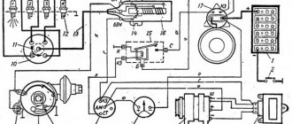
The ZMZ-402 and ZMZ-4021 engines are equipped with a non-contact ignition system consisting of a transistor switch, an ignition distributor of type 19.3706, an ignition coil of type B116 or B116-01, spark plugs and high-voltage and low-voltage wires
The ignition distributor sensor (1908.3706) is non-contact, with a control pulse sensor (generator) and built-in vacuum and centrifugal ignition timing regulators.
The distribution sensor performs two functions: it sets the moment of sparking and distributes high voltage pulses among the cylinders in accordance with the order of their operation.
For this purpose, a slider mounted on the shaft of the sensor-distributor is used. An interference suppression resistor* is installed in the slider.
Instead of a resistor, part of the sensors has a cover with a central carbon contact.
The switch (1313734) opens the power supply circuit of the primary winding of the ignition coil, converting the sensor control pulses into current pulses in the ignition coil.
Ignition coil
Removal
1. Unscrew nuts 1 and disconnect low-voltage wires from coil terminals 3.
Disconnect high-voltage wire 4 from the ignition coil.
Unscrew nuts 2 and remove coil 3 (Fig. 2).
Examination
1. Ignition coils B116 and B116–01 are checked on a mod. K–295.
The coil must ensure uninterrupted sparking at the spark gap with a gap of 7 mm at a rotation speed of the ignition distributor shaft of at least 2500 rpm.
Inspect the coil. If the plastic cover has chips, cracks, signs of heating or oil leakage, replace the coils.
Check the resistance of the primary winding of the ignition coil by connecting an ohmmeter between the low voltage terminals.
The ohmmeter should show a resistance of 0.48–0.72 ohms.
Then check the resistance of the secondary winding by connecting an ohmmeter between the high voltage terminal and the “K” terminal of the coil.
The ohmmeter should show a resistance of 13,200–19,800 ohms. If the measured parameters differ, the coil must be replaced.
Ignition system switch
A transistor switch type 131.3734 or 90.3734 is installed on the left mudguard behind the battery.
It converts the control pulses of the Hall sensor in the ignition distributor into current pulses in the primary winding of the ignition coil.
Since the switch generates a large amount of heat during operation, it is necessary to periodically clean the switch housing from dirt and dust and not cover it with foreign objects.
1. Remove the switch from the car by unscrewing the two fastening nuts and disconnecting the wires.
2. Assemble the circuit shown in Figure 3 on a suitable metal plate.
Secure the tip of high voltage wire 5 at a distance of 6–7 mm from the plate.
When switch 4 is turned on, ammeter 1 should show a current within 6–7 A, and after 1–3 s the current should drop to 0.
At the moment the switch 4 is turned off, a spark should jump between the tip of the high voltage wire 5 and the plate (permanent sparking is possible).
Otherwise, switch 3 is faulty and must be replaced.
Checking the spark plugs yourself
According to the wiring diagram for engines 405, 406 and 409, spark plugs are used to transfer spark from the switchgear to the engine cylinders. If the operation of the SZ is disrupted, this may affect the quality of the motor as a whole.
To check devices you will need an assistant:
- You need to disconnect the high-voltage wire from the first SZ.
- Using a key, the product is unscrewed from its seat.
- One end of the device from the electrode side should be brought to the engine or metal on the car body, the distance between the electrode and the ground should be about 1-2 mm.
- The assistant then turns the starter to try to start the engine. If at the moment of cranking a spark jumps between the electrode and the body, this indicates that the product is operational. In the same way, you need to check each SZ. Please note that problems with spark supply can also be caused by improper operation of the distributor, as well as damage to high-voltage wires.
Adjusting and installing the ignition ZMZ 402: secrets and tips
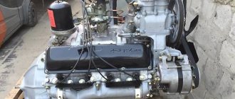
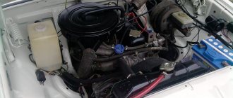
The ZMZ 402 engine is one of the products of the Russian automotive industry, widely used in the automotive industry. These power units were equipped with certain models of Volga, UAZ, and Gazelle cars. To ensure normal engine operation, the machine must have the ignition set correctly. In this article we will tell you how to install a distributor on a 402 engine and what should be taken into account when performing the task.
In order to properly configure and adjust the ignition of the ZMZ 402, you need to know some nuances about the operation of the power unit. Such motors have a non-contact distributor installed, supplemented by a control signal generator and mounted advance regulators - vacuum and centrifugal (video author - smotri Vidik).
The distributor is designed to perform certain functions:
- determines the moment of spark occurrence;
- transmits high voltage signals through the cylinders of the power unit, taking into account the order of their operation.
For the correct distribution of impulses, a slider mounted on the mechanism pulley is used. The slider is equipped with a resistor and is designed to suppress interference. The switching device performs the function of opening the ignition coil winding circuit, converting control signals from the regulator into short-circuit current signals.
To correctly install the ignition on a 402 engine, it is necessary to take into account the system characteristics presented below:
- the order of operation of the cylinders is first the first, then the second, then the fourth and third;
- the rotor of the distribution element rotates counterclockwise;
- on a centrifugal device the advance angle is from 15 to 18 degrees;
- on a vacuum device this indicator is from 8 to 10 degrees;
- the play on the NW should be no more than 0.8 mm;
- the resistor resistance value should be from 5 to 8 kOhm;
- the SZ resistance parameter should vary around 4-7 kOhm;
- in the stator winding the resistance level should be no more than 0.45 and no less than 0.5 kOhm.
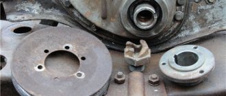
Disassembled distributor for ZMZ
How to install the ignition yourself?
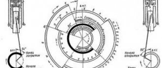
How is the ignition installed on the ZMZ 402? The crankshaft must be placed in a position that corresponds to an advance angle of 5 degrees.
You need to set the moment like this:
- On the power unit, we combine the average mark on its shaft on the cylinder head cover, that is, at the end of the compression stroke on cylinder 1.
- If the distributor has not been removed from the power unit, the compression stroke on cylinder 1 can be detected by opening its cover. It is necessary that the slider be installed opposite the internal contact, which is connected via a cable to the spark plug. If it is not possible to determine the compression in this way, you can dismantle the SZ installed in the first cylinder. After this, the hole will need to be covered with a rag, or better yet, with paper. The crankshaft needs to start rotating, and at the moment when the paper plug is knocked out by the air flow, the compression stroke begins.
- Now you will need a 10mm wrench - with its help you need to slightly loosen the octane corrector bolt, but you do not need to unscrew the screw itself.
- Next, you should set its scale to zero, this is approximately the middle of the scale.
- After completing these steps, using a 10mm wrench, you need to loosen the bolt that secures the octane corrector plates.
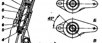
- Now you need to rotate the distributor body so that the marks are aligned. In particular, we are talking about the red mark located on the rotor, as well as the risk on the stator. When the installation of the device drive is completed, the distributor must be held in this position with one hand, and the bolt must be tightened with the other hand.
1. Place marks. 2. Set the scale to zero. 3. Align the distributor marks.
Many people set the ignition to a strobe light. Sometimes setting the ignition timing does not produce results - the engine continues to stall and not operate at full power. The reason is the inoperability of the distributor as a whole. The problem can be solved by replacing or repairing the distributor.
Video “Step-by-step installation of distributor on ZMZ 402”
Typical unit malfunctions and ways to eliminate them
A malfunction in the operation of the short circuit can occur for the following reasons:
- There is a short circuit within the system, which may cause the device to overheat. If the operating temperature exceeds 150 degrees, the product will fail irrevocably.
- The second reason is a faulty power supply from the car's electrical network. As you know, for normal operation of electrical devices, the voltage level in the on-board network must be at least 11.5 volts. If the power is too low, it will take much longer to charge the short circuit.
- The device may also fail due to mechanical damage to the insulation. This problem is usually associated with engine fluid entering through worn out seals.
- Poor contact of the product with the on-board network. If the short circuit housing is damaged, this may cause moisture to enter the primary or secondary windings, which in turn can lead to the appearance of transition resistance.
- Thermal problems. Some short circuit models are more susceptible to heat generation than others, which can also affect their service life.
- As a result of exposure to engine vibrations, the performance of the short circuit may also be impaired.
Ignition system elements
One of the main systems necessary for a successful engine start is the ignition system. For gasoline engines, the fundamental design of ignition systems differs very slightly - there are two types: • Contact system • Contactless system
The ignition system consists of the following components: 1. Coil 2. Distributor-spark breaker (distributor) 3. Switch 4. Spark plugs 5. Ignition switch 6. Starter 7. Additional resistance (in some cases)
Eventually
From the factory, the UMZ4216 gasoline engine of the GAZelle Business vehicle is equipped with Brisk LR15YC spark plugs. They should be replaced by the same ones, since they are unpretentious for 30,000-40,000 km. Analogues from BOSCH, NGK, BERU, DENSO performed no worse. A good option is the domestic A17DVRM.
Replacing ignition elements is quite primitive. Disconnect the ground, remove the wire, clean the space around the spark plug and unscrew it with a 21 spark plug wrench. Afterwards, a new part is screwed in.
The UMZ-4216 engine ignition system is non-contact with low-voltage distribution of ignition pulses across channels, with two two-terminal ignition coils. Each coil supplies high voltage simultaneously to the spark plugs of two cylinders, the pistons of which are located near TDC.
UMZ-4216 engine ignition system, fuel supply and ignition control, electrical diagram of the UMZ-4216 engine control system.
One of the coils of the UMZ-4216 engine ignition system supplies voltage to the first and fourth cylinders. The other goes to the second and third. In this case, in one of the cylinders of each pair there will be the end of the compression stroke, in the other - the end of the exhaust stroke. The mixture is ignited in the cylinder where the compression stroke occurs. Spark plugs are of the BRISK LR15YC type.
The ignition timing control system uses a GT305 or 18.3855 piezoelectric knock sensor. The sensor serves to detect engine detonation and allows the control unit to adjust the ignition timing until detonation is eliminated. The sensor is installed on the engine on the top, on the right, between the second and third cylinders. Connects to the wiring harness using a two-prong snap-on receptacle.
How the ignition system works
For the ZMZ 402 model, this order looks like this:
The car engine is started by turning the key in the ignition switch - at this moment the charge from the battery is supplied to the starter, which begins to rotate the crankshaft, activating the distributor (via the drive). At this very moment, electric current is supplied to the coil, then through the commutator the charge is supplied to the spark distributor (distributor), which in turn distributes the current through the wires to the cylinder spark plugs.
IMPORTANT to know that the switch is a block of transistor switches that serves to control the currents that pass through the inductor.
Early ignition
One of the most common problems with the ignition system is too early an ignition timing angle - this is when, when fuel is supplied to the engine cylinder, the working mixture of gasoline and air in the combustion chamber ignites much earlier than the piston approaches top dead center. If the initial ignition timing is set too early, then problems with the vehicle's performance may occur. To avoid this, you should pay attention to signs of early ignition. And this is: • The engine does not start the first time (the crankshaft turns in the opposite direction when starting the engine) • Unstable operation of the engine at idle • Detonation of unburned fuel (a chirping sound appears that does not disappear when the speed increases) • Carbon deposits on the spark plugs ignition (fuel that is not completely burned is deposited on the spark plug) • Shots in the muffler (fuel burns due to misfire of the ignition) • Black smoke from the muffler (fuel that is not burned in the combustion chamber burns out) • Increased fuel consumption
Late ignition
On engines with a carburetor power supply system, late ignition is the ignition of the fuel mixture at the moment when the piston has already reached top dead center or has already passed it. When the engine operates this way, fuel consumption increases, power and throttle response deteriorate. The main signs of late ignition are: • Trouble starting the engine (several attempts are needed) • Sluggish vehicle dynamics while driving (the engine stalls when the speed increases) • Spark plugs are light gray or white • Shots in the carburetor (fuel burns out in the intake manifold) ) • Engine overheating (the mixture burns out during the expansion stroke, which contributes to engine overheating)
Malfunctions and their elimination
Like any technical product, the Gazelle-Business motor is susceptible to breakdowns. Sometimes it needs repairs for various reasons. The most common problems that arise are:
- The motor does not start. Most likely there is no fuel supply to the injectors. It is necessary to use the appropriate fuel, rinse and clean the fuel intake.
- The tightness of the pipeline between the tank and the electric pump is broken. The connection points should be checked and the tightness restored.
- There are problems with the control electronics. It is necessary to replace faulty parts of the unit.
- Poor power delivery indicates problems in the electronic control system. After testing, it is necessary to replace the unusable element.
- The fine filter is clogged. In this case, the filter element must be replaced.
- Air appears in the fuel block. It is necessary to check and ensure the tightness of the system.
- If problems are detected in the fuel pump, the faulty injectors should be replaced.
Procedure for adjusting the ignition system
Label matching
To begin setting the correct ignition timing, you need to turn the crankshaft to a position that indicates 5 degrees. This is done as follows - you need to set the first cylinder at top dead center (end of the compression stroke). To do this, you need to align the middle mark on the crankshaft pulley with the mark on the cylinder head.
ATTENTION. The compression stroke on the first cylinder can be set if the distributor has not been removed before - by opening its cover, the slider will stand opposite the internal contact of the wire connecting to the spark plugs of the first cylinder.
If it is not possible to determine the compression stroke in this way, then it is necessary to unscrew the spark plug from the first cylinder and plug the hole with a rag or paper. Then you should start cranking the crankshaft until the paper-shaped plug is removed with the help of air created inside the cylinder. This will be the moment of compression.
Advance angle adjustment
Next, you need to loosen the octane corrector bolt, which is located on the distributor. A 10mm wrench will come in handy here. Then the advance angle is set approximately in the middle of the scale (this will be zero). Next, using the same 10mm wrench, you need to loosen the bolt securing the octane corrector plates. The next step is to rotate the distributor housing so that both marks coincide - the red mark on the rotor head and the mark on the stator. When the housing is installed in the desired position, it is necessary to fix the distributor housing with one hand and tighten the bolt with the other.
Checking the correct installation of the ignition
The correctness of the set ignition timing is checked while the car is moving - at a speed of 50-60 km/h, the gas pedal is sharply pressed, a short-term detonation should follow (1-3 seconds). If detonation disappears after this time, then the moment was chosen correctly. You can set the ignition more accurately using a strobe light.
This short guide will help you set the ignition yourself without resorting to the help of specialists at home.
Installing a new power steering belt
Install the new belt, with the teeth facing inward, onto all the rollers from which the belt was removed when replacing.
Tension the power steering pump and tighten the bolts. In step 9 we used a pry bar to move the control pump forward to relieve the tension. In this step we need to perform a reverse process by pulling the pump in the reverse direction. to apply tension to the pulley.
Tension the power steering belt in this way and, without loosening it, tighten the lower bolt, and then the upper bolt. Once both bolts are tightened, release the tension on the pry bar and proceed to the next step.
Tighten the tension roller and tighten the bolts. Using the same method as above, apply pressure to the idler pulley until the belt is tensioned at all three access points.
Install everything that was removed and removed to access the power steering belt. Put the alternator belt back on, install the engine crankcase protection and connect the battery cables.
Start the car. Listen carefully to all the sounds coming from under the hood of the car. Pay attention in particular to whistling or squealing noises. If you hear such sounds, turn off the engine and recheck the tension of the belts (power steering and generator, if the latter was removed).
If you do not hear any symptoms, proceed to test drive the car for about 10-15 km. When you arrive home, open the hood and tighten all the power steering belt bolts again, because during long-term operation of the engine after the first start, they could have become loose.
It won’t start: reasons and what to do
If the unit starts poorly in hot weather or there is no spark, then it is recommended:
- Adjust the gaps between the tips of the valve stems and the rocker arm pressure bolts.
- Unscrew the cylinder head and grind the valves.
- Inspect the ignition system for defects.
- Tighten the ignition system and carburetor mounting bolts.
- Remove the fuel and cooling system jets, wash and blow them with compressed air.
- Dismantle the carburetor, remove the mixing chamber, unscrew the fuel system nozzle and idle screw, and blow out the channels with compressed air.
- Replace the crankshaft oil seal with a new one.
What you need to know
In order to properly configure and adjust the ignition of the ZMZ 402, you need to know some nuances about the operation of the power unit. Such motors have a non-contact distributor installed, supplemented by a control signal generator and mounted advance regulators - vacuum and centrifugal (video author - smotri Vidik).
The distributor is designed to perform certain functions:
- determines the moment of spark occurrence;
- transmits high voltage signals through the cylinders of the power unit, taking into account the order of their operation.
For the correct distribution of impulses, a slider mounted on the mechanism pulley is used. The slider is equipped with a resistor and is designed to suppress interference. The switching device performs the function of opening the ignition coil winding circuit, converting control signals from the regulator into short-circuit current signals.
Story
It was developed by no less legendary designer Harry Voldemarovich Evart specifically for the Volga. This power unit was supposed to replace the outdated GAZ-21 engine. In subsequent development, many modifications were made, such as ZMZ-24D and ZMZ 4021.
This engine is also called ZMZ 24, since it was initially intended to be installed only on the 24th Volga, but as practice and history have shown, the engine has become quite widespread in other car models.
The ZMZ 24D engine had improved cooling characteristics, which reduced fuel consumption. But this series of engines was interrupted in 1972, because repairs to the power unit were too expensive.
Subsequently, VOLGA received only two power units - ZMZ 402 and ZMZ 402.1. But, as practice shows, the use of ZMZ 24 and ZMZ 24D power units has reached our time, and such engines can still be found on some 24-series cars.
How to install the ignition yourself?
How is the ignition installed on the ZMZ 402? The crankshaft must be placed in a position that corresponds to an advance angle of 5 degrees.
You need to set the moment like this:
- On the power unit, we combine the average mark on its shaft on the cylinder head cover, that is, at the end of the compression stroke on cylinder 1.
- If the distributor has not been removed from the power unit, the compression stroke on cylinder 1 can be detected by opening its cover. It is necessary that the slider be installed opposite the internal contact, which is connected via a cable to the spark plug. If it is not possible to determine the compression in this way, you can dismantle the SZ installed in the first cylinder. After this, the hole will need to be covered with a rag, or better yet, with paper. The crankshaft needs to start rotating, and at the moment when the paper plug is knocked out by the air flow, the compression stroke begins.
- Now you will need a 10mm wrench - with its help you need to slightly loosen the octane corrector bolt, but you do not need to unscrew the screw itself.
- Next, you should set its scale to zero, this is approximately the middle of the scale.
- After completing these steps, using a 10mm wrench, you need to loosen the bolt that secures the octane corrector plates.
- Now you need to rotate the distributor body so that the marks are aligned. In particular, we are talking about the red mark located on the rotor, as well as the risk on the stator. When the installation of the device drive is completed, the distributor must be held in this position with one hand, and the bolt must be tightened with the other hand.
Many people set the ignition to a strobe light. Sometimes setting the ignition timing does not produce results - the engine continues to stall and not operate at full power. The reason is the inoperability of the distributor as a whole. The problem can be solved by replacing or repairing the distributor.
Engine 402 ZMZ - valve adjustment, operating procedure
Author:
Maxim Markov
During the operation of the car, the need for adjustment work periodically arises, be it correcting the ignition angle or adjusting valve clearances. And the 402 engine needs to perform a valve adjustment procedure every 15 thousand kilometers, since if the thermal clearances are broken, the internal combustion engine (ICE) will lose power and fuel consumption will increase. This article will discuss exactly this.
Technical characteristics of the Volga
The engine is an in-line four, an eight-valve mechanism. Many parts of the gas 24 engine were made of aluminum-zinc alloy: the internal combustion engine block, the cylinder head, the intake manifold. The body was produced in two versions - sedan and station wagon.
The volume of the fuel tank was 55 liters, since the consumption was relatively large, the tank had to be not small. It was located under the bottom of the trunk. Another feature of the tank was two sensors for measuring the amount of fuel. Manually, by placing the car on a flat surface, you could unscrew the plate with divisions from the tank, which showed the remaining fuel on the instrument panel.
The latter often failed and car owners often used a manual one. Fuel consumption ranged from 10-13 liters per 100 km. Transmission - 4-speed with synchronizers for all gears, single disc clutch, dry with hydraulic drive. Chassis: front independent, multi-link, pivot type. Rear: dependent, spring. Shock absorbers are telescopic, double-sided. Braking system: drum, installed on all 4 wheels. Parking brake with rear wheel drive.
Source
Frequency of adjustment work
The frequency of adjustment directly depends on driving style, vehicle load, and the correct use of a particular brand of gasoline. If the car is operated without harsh driving and is not heavily loaded, then the adjustment period is 15 thousand km; if the vehicle is used for cargo transportation, then 10 thousand km. Well, if the wrong type of fuel is used for the cylinder head (cylinder head), regardless of the settings of the ignition system, the valve clearances are adjusted after 5-6 thousand kilometers.
The GAZ family of cars is equipped with the following internal combustion engine models: 402, 405 and 406 engines. The 402 engine is installed on both the Volga and GAZelle. Now it’s worth moving on to the indicators of acceptable standards.
Powertrain capabilities
Owners of the Gazelle-405 car are impressed by the fuel-injector engine, especially in terms of fuel consumption. It ranges from 8 liters on the highway to 13 in the combined cycle when driving around the city. Oil is also used sparingly: approximately 100 grams per thousand kilometers. In a single-point system, the manifold is equipped with only one injector for all cylinders. In a distributed block, each of them has its own collector. And with direct injection, fuel is supplied directly to the cylinders, just like a diesel engine.
Permissible clearance standards
Why is valve adjustment done at all, and what happens if it is not done on time? The consequences can lead to cylinder burnout and, as a result, to expensive and time-consuming repairs of the 402 engine. In other words, this procedure allows you to maintain internal combustion engine parts in working condition.
There are several clear signs that it is time for an adjustment procedure:
- knocking of valves in the engine;
- unstable work ;
- power drop;
- increased fuel consumption.
Acceptable standards are presented below:
- 1 and 4 cylinders. For these cylinders, the tolerance values on the suction valves will be in the range of 0.40-0.45 mm, and for the exhaust valves 0.35-0.40 mm.
- 2 and 3 cylinders. Here the indicators at both the intake and exhaust will be in the range of 0.40-0.45 mm.
Briefly about the UMZ 4216 engine
The first experimental batches of engines of this class began to be produced in 2003. Ten years later, power plants began to comply with EURO-4 standards. Despite its age, the technical specification of the product is quite modern:
- Maximum potential – 106.8 hp.
- The total volume is 2.89 liters.
- Maximum thrust – 235.7 Nm. Achieved when the tachometer needle is in the range of 2,000-2,500 rpm.
The manufacturer provided an extended warranty. It was preserved even when HBO was installed on the car. In the basic version, the car uses 92-grade gasoline - this is the main type of fuel. The 95th is recognized as auxiliary - it also does not harm the engine.
- Aluminum block with 4 cast iron sleeves.
- Four-chamber cylinder head with 8 valves.
- ECU - MIKAS with sensors for camshaft, crankshaft, throttle assembly, detonation, absolute pressure.
Preparatory process
Before you begin adjustment work with your own hands, you need to prepare the necessary tools and consumables, which include:
- set of measurement probes;
- a set of wrenches (socket or ring);
- new valve cover gasket;
- crankshaft ratchet key;
- spark plug wrench Needed to remove spark plugs;
- Phillips and flathead screwdrivers;
- clean rags.
Upon completion of preparation, when all the required tools are prepared, you can proceed directly to the adjustment work.
The process of adjusting the angles of thermal gaps
For those who are wondering how to adjust the valves on a car with a 402 engine, the entire process will be presented in detail below. It is important to remember that the process itself should be performed on a cold engine, since on a warm engine the combustible mixture can burn the motorist. Valve adjustment on a 402 engine is performed in the following way:
- Disconnecting the hose. The first step is to disconnect all the hoses going to the valve cover, as well as the accelerator cable.
- Removing the air filter and valve cover. Then you should remove the air filter with the housing, and unscrew the 6 bolts securing the valve cover.
- Removing the spark plugs.
- Installing the first cylinder at TDC. The next step in the adjustment process is to set the first cylinder to the top dead center (TDC) position. To do this, it is necessary that the third mark on the crankshaft pulley coincides with the mark on the engine block housing. This is done by turning the crankshaft.
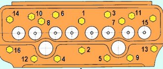
- Sequence of valve adjustment. The order of adjusting the valves is as follows: 1, 2, 4, 6, the next step is to turn the crankshaft one full turn clockwise until the marks coincide. Next, 3, 5, 7, 8 valves are adjusted.
- Adjustment process. Using an 11-mm socket or a screwdriver, you need to hold the adjusting screw, and at this moment unscrew the nut securing it. Using a probe of the required size, take a measurement (the probe should move with little effort); if the measurement of the thermal gap is normal, then you can move on to the next valve.
- Installation work. The next step is to assemble in reverse order, i.e. the spark plugs, valve cover with a new gasket are installed back, but the bolts must be tightened according to the recommended tightening torques (this indicator is 0.5-0.8 N.m (kg.m)), the air filter and hoses.
- Check with the engine running. Now you should start the internal combustion engine and let it run for a while until it warms up completely, then listen to its operation. If there is no metallic ringing or dull clattering sound, this will mean that the thermal clearance adjustment has been performed correctly.
Service
UMZ-4216 is a simple and unpretentious engine designed for commercial vehicles. Engine maintenance must be carried out regularly, in accordance with the maintenance schedule.
Maintenance work is divided into 3 groups:
Every day in the UMZ-4216 engine it is necessary to check the oil level, coolant, tightness of the cooling system, lubrication system and fuel supply lines. With in-depth control, which is carried out according to a schedule, the following is added to these works:
According to the approved regulations, the following manipulations are performed on the UMZ-42616 engine every six months:
Communities › GAZ Volga › Blog › Correct ignition adjustment of ZMZ 402.
Hi all ! I needed to set the ignition to 402. On the Internet, everyone writes differently! 1 Please tell me, STEP BY STEP! how to set the ignition correctly on 402? (electronic ignition, conventional) I will display it on the street near the house. 2 Does the distributor slider rotate clockwise or counterclockwise? 3 Trying to start the car, it turns, but does not start, and after releasing the ignition key, the crankshaft turns in the opposite direction. (late ignition?) So I decided to set the ignition again from scratch! PLEASE TELL US HOW TO DO IT WITHOUT MUCH WORRY. As soon as I start the car, I will adjust it using the strobe light.
TODAY I SET THE IGNITION! THE CAR STARTED WITH ALMOST HALF A KICK! BUT there is a question: when the slider is on the first cylinder, unscrew the rear bolt and align the marks on the distributor under the slider, BUT! the slider has free movement, I turned it clockwise all the way and aligned the marks. DID I DO IT RIGHT? OR maybe you need to turn it counterclockwise all the way?
P.S. I still have to buy a new carburetor!