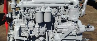
General description, design and scope of application of the A-01 motor
Altai diesel brand A-01 is a four-stroke six-cylinder engine without gas turbine supercharging, with a working volume of 11.15 liters, liquid cooling, with a vertical in-line cylinder arrangement and direct diesel fuel injection, with two separate heads.
It was produced in two main modifications: A-01 and A-01M (it should be noted that the original factory designation for this engine was AM-01).
The scope of application of the A-01 and A-01M diesel engines was quite wide. In addition to agricultural and skidding tracked tractors T-4 (T-4A, TT-4, TT-4M), diesel graders of the A-01 family were also equipped with motor graders DZ-122, DZ-143, DZ-180, auto-loaders TO-18, TO- 28, excavators EO-121, EO-4124, road pavers DU-58, DU-62, as well as MTP-71A, MTP-7, LP-19A.
In addition, Altai engines of the A-01 family were also installed in diesel power plants; for pumping and drilling rigs.
The power of the A-01 family engines is 135 hp. With. (99.29 kW), at a crankshaft speed of around 1700 rpm. The maximum torque of the A-01 engine is 570 N.m, and the maximum torque of the A-01M engine is 630 N.m, at 1200-1300 rpm. The torque reserve is at least 15 percent, and the specific diesel fuel consumption is within the range of 170 g/l. With. h.
Many components and parts of the Altai A-01 diesel engine are unified with the corresponding components and parts of YaMZ-236 diesel engines produced by the Yaroslavl Motor Plant. These are, in particular, pistons, liners, valves, injector nozzles and some auxiliary units.
Naturally aspirated diesel engines of the A-01 family are equipped with a two-valve gas distribution mechanism. In terms of emissions into the atmosphere, they met the requirements of Gosstandart GOST R 41.96-2005.
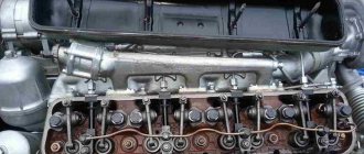
The A-01 diesel cylinder block is cast iron, the cylinder liners are “wet”, two interchangeable cylinder heads are made of special heat-resistant cast iron. The cylinder block is the basis for mounting all components and assemblies of the power unit, which is a rigid casting with precisely machined seats for cylinder liners, camshaft bushings, crankshaft bearing shells, and fuel pump bracket.
The cast iron casting is divided into compartments by vertical partitions. The end walls and vertical partitions of the A-01 cylinder block have bosses in the lower part that form supports for the main bearing shells. The camshaft supports are located in the vertical partitions of the A-01 cylinder block.
The A-01M engine is equipped with a pair of interchangeable cylinder heads. The head contains valves with springs, rocker arms, valve rockers, and injectors.
The cylinder head is a one-piece casting made of special cast iron, fixed to the block by means of heat-treated chromium-nickel steel studs. The head nuts are tightened evenly, in accordance with a certain sequence.
The nuts are tightened with a torque of 16-18 kgf/m, after running in a new or repaired engine, and then after a certain period of time (every 960 m/h). Once the nuts are tightened, the valve clearances and the clearances in the decompression mechanism are also checked.
In order to ensure heat dissipation, the cylinder head is equipped with a water jacket, which communicates with the water jacket of the cylinder block. The joints between the cylinder head and the block are sealed using a gasket. The exhaust valve seats are inserts made of heat-resistant cast iron, which are pressed into seats with interference fit. Processing of valve seats and guide bushings occurs after they are pressed into the head.
The cylinder diameter of the A-01 engine is 130 mm, the piston stroke is 140 mm. The stroke to bore ratio is 1.08, which is characteristic of a long stroke engine. The compression ratio is 16.5.
The combustion chamber is single-cavity, located in the piston bottom, the number of valves is 12 (they are located in the engine cylinder head).
It should be noted that in the six-cylinder A-01 engines it was possible to achieve a balance of inertial forces of the 1st and 2nd orders, which significantly reduced engine vibrations during operation.
The dry weight of the A-01 six-cylinder diesel engine is 1250 kg (including clutch).
automagadan
A small table with engine weights. It may be useful for calculating the cost of delivery of engines or for self-design.
Daihatsu, Hino, Honda, Isuzu, Mazda, MMC, Nissan, Rover, Subaru, Suzuki, Toyota
Daihatsu (petrol) EF ——— 659 cc; 90.00 kg; Daihatsu (petrol) EJ ——— 989 cc; 140.00 kg; Daihatsu (petrol) HD ——— 1589 cc; 110.00 kg; Hino (diesel) EC100 ——— 5010 cc; 360.00 kg; Hino (diesel) W06E ——— 6014 cc; 380.00 kg; Honda A18A ——— 1829 cc; 160.00 kg; Honda B16A FF injection DOHC VTEC ——— 1595 cc; 138.00 kg; Honda B18B ——— 1834 cc; 125.00 kg; Honda B18C ——— 1797 cc; 120.00 kg; Honda B20B FF SM-X ——— 1972 cc; 150.00 kg; Honda C32A 4WD coil. ——— 3206 cc; 217.00 kg; Honda D13B FF carb. 1CAM 16cl ——— 1343 cc; 105.00 kg; Honda D15B FF injection 1CAM 16cl VTEC-E ——— 1493 cc; 115.00 kg; Honda D16A ——— 1590 cc; 120.00 kg; Honda F18A ——— 1849 cc; 140.00 kg; Honda F18B ——— 1849 cc; 135.00 kg; Honda F20B FF 2CAM, DONC, VTEC injection ——— 1997 cc; 150.00 kg; Honda F22A ——— 2156 cc; 145.00 kg; Honda F22B FF passenger car 1CAM VTEC ——— 2156 cc; 145.00 kg; Honda F23A 4WD Odysey (RA4) 1 cam, VTEC ——— 2253 cc; 145.00 kg; Honda G20A ——— 1996 cc; 265.00 kg; Honda G25A FF Inspaer ——— 2451 cc; 170.00 kg; Honda H22A FF DOHC, VTEC ——— 2156 cc; 165.00 kg; Honda H23A ——— 2258 cc; 160.00 kg; Honda J25A Odissey ——— 2495 cc; 170.00 kg; Honda J25A Saber ——— 2495 cc; 170.00 kg; Honda J30A ——— 2997 cc; 190.00 kg; Honda K20A ——— 1998 cc; 150.00 kg; Honda L13A ——— 1339 cc; 100.00 kg; Honda L15A ——— 1496 cc; 100.00 kg; Honda ZC FF injection 1CAM 16cl VTEC ——— 1590 cc; 130.00 kg; Isuzu (diesel) 4BC1 ——— 3260 cc; 320.00 kg; Isuzu (diesel) 4BC2 ——— 3567 cc; 350.00 kg; Isuzu (diesel) 4BD1 ——— 3856 cc; 320.00 kg; Isuzu (diesel) 4BE1 FR truck (plunger injection pump) ——— 3636 cc; 325.00 kg; Isuzu (diesel) 4BE2 FR truck (plunger injection pump) ——— 3630 cc; 325.00 kg; Isuzu (diesel) 4EE1 ——— 1686 cc; 164.00 kg; Isuzu (diesel) 4FD1 ——— 2189 cc; 270.00 kg; Isuzu (diesel) 4FG1 injection pump ——— 2380 cc; 270.00 kg; Isuzu (diesel) 4HF1 FR truck ——— 4334 cc; 330.00 kg; Isuzu (diesel) 4HG1 FR truck ——— 4570 cc; 404.00 kg; Isuzu (diesel) 4JB1 FR truck ——— 2771 cc; 192.00 kg; Isuzu (diesel) 4JG2-T 4WD Bighorn Intercooler (fuel pump mechanical) ——— 3059 cc; 260.00 kg; Isuzu (diesel) 4JX1 ——— 2999 cc; 280.00 kg; Isuzu (diesel) 6HE1 ——— 7127 cc; 385.00 kg; Isuzu (diesel) FE6 ——— 6925 cc; 670.00 kg; Mazda (diesel) DL-T with gearbox ——— 2765 cc; 260.00 kg; Mazda (diesel) R2 4WD ——— 2184 cc; 178.00 kg; Mazda (diesel) RF 4WD Bongo thermal front ——— 1998 cc; 180.00 kg; Mazda (diesel) SL FR truck 24v (fuel injection pump plunger) ——— 3455 cc; 254.00 kg; Mazda (diesel) TF FR Titan truck ——— 4021 cc; 356.00 kg; Mazda (diesel) VS minibus, before '95. ——— 2956 cc; 260.00 kg; Mazda (diesel) WL-T FR 4WD PROCEED ——— 2499 cc; 234.00 kg; Mazda (diesel) XA FR ——— 2522 cc; 255.00 kg; Mazda (diesel) PN ——— 1720 cc; 155.00 kg; Mazda (petrol) B3 FF Ford mono injection 1CAM 16kl, wedge. ——— 1323 cc; 115.00 kg; Mazda (petrol) B5 4WD passenger carb. 1CAM ——— 1498 cc; 115.00 kg; Mazda (petrol) B6 ——— 1597 cc; 140.00 kg; Mazda (petrol) BP ——— 1839 cc; 143.00 kg; Mazda (petrol) D5 ——— 1490 cc; 100.00 kg; Mazda (petrol) E5 ——— 1490 cc; 120.00 kg; Mazda (petrol) F8 ——— 1789 cc; 155.00 kg; Mazda (petrol) FE ——— 1998 cc; 165.00 kg; Mazda (petrol) FP FF DOHC (distributor) Capella ——— 1839 cc; 129.00 kg; Mazda (petrol) FS 4WD Capella coil side old, 16cl DOHC ——— 1991 cc; 136.00 kg; Mazda (petrol) G6 ——— 2605 cc; 150.00 kg; Mazda (petrol) HA ——— 2977 cc; 370.00 kg; Mazda (petrol) K8 ——— 1844 cc; 165.00 kg; Mazda (petrol) KF ——— 1995 cc; 175.00 kg; Mazda (petrol) KL passenger ——— 2496 cc; 171.00 kg; Mazda (petrol) LF ——— 1998 cc; 178.00 kg; Mazda (petrol) RF ——— 1998 cc; 178.00 kg; Mazda (petrol) RF-T ——— 1998 cc; 210.00 kg; Mazda (petrol) Z5 ——— 1489 cc; 125.00 kg; Mazda (petrol) ZJ FF Demio (DY3W) ——— 1348 cc; 103.00 kg; Mazda (petrol) ZL ——— 1498 cc; 118.00 kg; Mazda (petrol) ZL FF ——— 1498 cc; 145.00 kg. MMC (petrol) 4A30 ——— 659 cc; 105.00 kg; MMC (petrol) 4A31 ——— 1094 cc; 105.00 kg; MMC (petrol) 4G13 FF injection 1CAM ——— 1298 cc; 135.00 kg; MMC (petrol) 4G15 ——— 1468 cc; 135.00 kg; MMC (petrol) 4G32 ——— 1597 cc; 130.00 kg; MMC (petrol) 4G37 ——— 1755 cc; 135.00 kg; MMC (petrol) 4G54 ——— 2555 cc; 200.00 kg; MMC (petrol) 4G63 4WD DONC 2CAM 16cl ——— 1997 cc; 160.00 kg; MMC (petrol) 4G63-T ——— 1997 cc; 170.00 kg; MMC (petrol) 4G64 FF injection 1CAM 16cl (distributor) ——— 2350 cc; 184.00 kg; MMC (petrol) 4G67 ——— 1836 cc; 170.00 kg; MMC (petrol) 4G91 Lancer carb. 2CAM 16cl DOHC ——— 1496 cc; 137.00 kg; MMC (petrol) 4G93 FF Galant carburetor. SOHC 16cl ——— 1834 cc; 150.00 kg; MMC (petrol) 4G93 GDI Pajero ——— 1834 cc; 145.00 kg; MMC (petrol) 4G94 ——— 1999 cc; 150.00 kg; MMC (petrol) 6A11 ——— 1829 cc; 177.00 kg; MMC (petrol) 6A11 FF passenger injection. DOHC, 24cl ——— 1829 cc; 220.00 kg; MMC (petrol) 6A12 ——— 1998 cc; 165.00 kg; MMC (petrol) 6A13 FF Legnum (distributor) ——— 2498 cc; 170.00 kg; MMC (petrol) 6G71 FF passenger car 2CAM CYCLON ——— 1998 cc; 220.00 kg; MMC (petrol) 6G72 4WD CHALLENGER, 12 valves, coils ——— 2972 cc; 195.00 kg; MMC (petrol) 6G73 FF passenger DOHC NEW (distributor) ——— 2497 cc; 194.00 kg; MMC (petrol) 6G74 ——— 3496 cc; 230.00 kg; MMC (petrol) G32B carburetor ——— 1600 cc; 120.00 kg; MMC (petrol) G37B ——— 1755 cc; 130.00 kg; MMC (petrol) G54B ——— 2555 cc; 150.00 kg; MMC (petrol) G63B-T-ECI FF Galant INTERCOOLER SIRIUS ——— 1997 cc; 150.00 kg; MMC (diesel) 4D30 ——— 3298 cc; 290.00 kg; MMC (diesel) 4D32 ——— 3567 cc; 300.00 kg; MMC (diesel) 4D33 FR Canter 24v NEW ——— 4214 cc; 360.00 kg; MMC (diesel) 4D33 FR narrow head ——— 4214 cc; 297.20 kg; MMC (diesel) 4D56-T 4WD Delica ——— 2476 cc; 193.00 kg; MMC (diesel) 4D65 auto. FF F4A212-URH ——— 1795 cc; 180.00 kg; MMC (diesel) 4D68-T 4WD passenger car NEW ——— 1998 cc; 170.00 kg; MMC (diesel) 4DR5 FR Canter (in-line injection pump) ——— 2659 cc; 242.00 kg; MMC (diesel) 4DR7 FR Canter (in-line injection pump) ——— 2835 cc; 242.00 kg; MMC (diesel) 4M40-T 4WD Delica ——— 2835 cc; 239.00 kg; MMC (diesel) 4M40-T 4WD Pajero (dimensions 65cmx80cmx80cm) ——— 2835 cc; 234.40 kg; MMC (diesel) 4M51 ——— 5249 cc; 250.00 kg; MMC (diesel) 6D15 ——— 6919 cc; 400.00 kg; Nissan (petrol) A15 FR Vanette carburetor. black valve cover new image ——— 1487 cc; 135.00 kg; Nissan (petrol) CA18 DE ——— 1809 cc; 160.00 kg; Nissan (petrol) CA18 FR passenger car. 2CAM ——— 1809 cc; 130.00 kg; Nissan (petrol) CA20 ——— 1973 cc; 145.00 kg; Nissan (petrol) CG10-DE FF ——— 997 cc; 90.00 kg; Nissan (petrol) CG13-DE FF Cube (Z10) ——— 1274 cc; 105.00 kg; Nissan (petrol) CGA3 ——— 1348 cc; 110.00 kg; Nissan (petrol) CR12 ——— 1240 cc; 120.00 kg; Nissan (petrol) CR14 ——— 1386 cc; 120.00 kg; Nissan (petrol) E15 ——— 1487 cc; 131.00 kg; Nissan (petrol) GA13 ——— 1295 cc; 146.00 kg; Nissan (petrol) GA15 ——— 1497 cc; 145.00 kg; Nissan (petrol) GA16 ——— 1596 cc; 146.00 kg; Nissan (petrol) KA24 FF Pressage DOHC 16cl ——— 2388 cc; 170.00 kg; Nissan (petrol) L20 FR passenger carburetor. ——— 1998 cc; 173.00 kg; Nissan (petrol) NA16 FR Atlas carburetor. SOHC ——— 1627 cc; 117.00 kg; Nissan (petrol) NA20 ——— 1998 cc; 140.00 kg; Nissan (petrol) QG15 ——— 1497 cc; 140.00 kg; Nissan (petrol) QG16 ——— 1597 cc; 140.00 kg; Nissan (petrol) QG18 4WD 2CAM, 16cl. ——— 1769 cc; 135.00 kg; Nissan (petrol) QR20 ——— 1998 cc; 150.00 kg; Nissan (petrol) RB20 ——— 1998 cc; 181.00 kg; Nissan (petrol) RB25-DE 4WD Skyline NEO ——— 2498 cc; 235.00 kg; Nissan (petrol) SR18-DI FF Bluberd ——— 1883 cc; 150.00 kg; Nissan (petrol) SR20-DE FR Serena direct coll. down, rear distributor (no power steering) ——— 1998 cc; 160.00 kg; Nissan (petrol) VG20-E FR ——— 1998 cc; 200.00 kg; Nissan (petrol) VG30-E 4WD TERRANO ——— 2960 cc; 220.00 kg; Nissan (petrol) VG33 4WD (distributor) Terrano (LR50) ——— 3300 cc; 230.00 kg; Nissan (petrol) VQ20 FF Cefiro 24 cl ——— 1995 cc; 175.00 kg; Nissan (petrol) VQ23 ——— 2349 cc; 200.00 kg; Nissan (petrol) VQ25 ——— 2495 cc; 185.00 kg; Nissan (petrol) VQ30-T FR Cedric ——— 2987 cc; 240.00 kg; Nissan (petrol) Z16 FR Datsun carburetor. ——— 1600 cc; 115.00 kg; Nissan (petrol) Z20 ——— 1952 cc; 150.00 kg; Nissan (diesel) BD30 FR Atlas 24v ——— 2953 cc; 245.00 kg; Nissan (diesel) CD17 ——— 1680 cc; 170.00 kg; Nissan (diesel) CD20 FR Serena ——— 1973 cc; 180.00 kg; Nissan (diesel) ED30 ——— 2956 cc; 180.00 kg; Nissan (diesel) ED33 ——— 3298 cc; 220.00 kg; Nissan (diesel) FD35 ——— 3465 cc; 300.00 kg; Nissan (diesel) FD42 ——— 4241 cc; 324.00 kg; Nissan (diesel) FD46 FR ——— 4617 cc; 295.00 kg; Nissan (diesel) LD20 FR m.bus ——— 1952 cc; 190.00 kg; Nissan (diesel) QD32 12v ——— 3153 cc; 225.00 kg; Nissan (diesel) RD28 Laurel ——— 2825 cc; 220.00 kg; Nissan (diesel) SD23 ——— 2289 cc; 205.00 kg; Nissan (diesel) TD23 FR Atlas 12v ——— 2289 cc; 230.00 kg; Nissan (diesel) TD25 ——— 2494 cc; 230.00 kg; Nissan (diesel) TD27-T 4WD m.bus ——— 2663 cc; 245.00 kg; Nissan (diesel) TD42 ——— 4169 cc; 365.00 kg; Nissan (diesel) YD22 FF ——— 2184 cc; 210.00 kg; Nissan (diesel) YD25-TE ——— 2488 cc; 200.00 kg; Nissan (diesel) ZD30-TE-DDTI 4WD Safari ——— 2953 cc; 242.00 kg; Nissan (petrol) Z18 ——— 1770 cc; 150.00 kg; Rover 16K4F ——— 1589 cc; 130.00 kg; Subaru EA71 ——— 1595 cc; 155.00 kg; Subaru EA82 4WD carburetor. ——— 1781 cc; 135.00 kg; Subaru EF10 ——— 997 cc; 105.00 kg; Subaru EF12 ——— 1189 cc; 105.00 kg; Subaru EJ15 ——— 1493 cc; 130.00 kg; Subaru EJ16 4WD passenger car DOHC 16cl ——— 1597 cc; 140.00 kg; Subaru EJ18 4WD ——— 1820 cc; 180.00 kg; Subaru EJ20 4WD coil. Legasy(BG5) DOHC ——— 1994 cc; 120.00 kg; Subaru EJ20-TT 4WD coil. DOHC BOXER INTERCOOLER (BH5), 83t.km.,99y. new image ——— 1994 cc; 160.00 kg; Subaru EJ22 ——— 2212 cc; 113.00 kg; Subaru EJ25 (without power steering, generator, AC) ——— 2457 cc; 107.00 kg; Suzuki F6A ——— 657 cc; 80.00 kg; Suzuki G10 ——— 993 cc; 90.00 kg; Suzuki G16A 4WD Escudo injection 16cl ——— 1590 cc; 105.00 kg; Suzuki H20A 4WD Escudo ——— 1998 cc; 155.00 kg; Suzuki H25A 4WD Escudo coil. 24cl ——— 2493 cc; 180.00 kg; Suzuki H27A ——— 2736 cc; 200.00 kg; Suzuki J18A ——— 1839 cc; 113.00 kg; Suzuki J20A Escudo ——— 1995 cc; 135.00 kg; Suzuki K10A ——— 996 cc; 90.00 kg; Suzuki M13A ——— 1328 cc; 102.00 kg; Suzuki M16A ——— 1586 cc; 135.00 kg; Toyota (petrol) 1AZ ——— 1998 cc; 130.00 kg; Toyota (petrol) 1FZ-FE ——— 4476 cc; 300.00 kg; Toyota (petrol) 1G-FE VVTI FR MarkII (GX100) BEAMS ——— 1988 cc; 160.00 kg; Toyota (petrol) 1G-GTE ——— 1998 cc; 209.00 kg; Toyota (petrol) 1JZ-GE (VVT-i) 4WD ——— 2491 cc; 200.00 kg; Toyota (petrol) 1KR-FE ——— 996 cc; 96.00 kg; Toyota (petrol) 1MZ-FE ——— 2995 cc; 180.00 kg; Toyota (petrol) 1NZ-FE VVTI 4WD passenger car. ——— 1496 cc; 112.00 kg; Toyota (petrol) 1S FF Vista (SV21) single injection ——— 1832 cc; 135.00 kg; Toyota (petrol) 1SZ-FE ——— 997 cc; 95.00 kg; Toyota (petrol) 1UZ-FE rear wheel drive Celsior coil. 32 valves TRC ——— 3969 cc; 220.00 kg; Toyota (petrol) 1VZ-FE ——— 1992 cc; 195.00 kg; Toyota (petrol) 1ZZ-FE ——— 1794 cc; 135.00 kg; Toyota (petrol) 2A ——— 1295 cc; 119.00 kg; Toyota (petrol) 2AZ-FE ——— 2362 cc; 170.00 kg; Toyota (petrol) 2JZ-GE FR MarkII ——— 2997 cc; 230.00 kg; Toyota (petrol) 2MZ FF ——— 2496 cc; 177.00 kg; Toyota (petrol) 2NZ-VVTI FF coils ——— 1298 cc; 88.00 kg; Toyota (petrol) 2TZ-FE ——— 2438 cc; 175.00 kg; Toyota (petrol) 2ZZ front-wheel drive, Celica, Yamaha cylinder head ——— 1795 cc; 135.00 kg; Toyota (petrol) 3A ——— 1452 cc; 135.00 kg; Toyota (petrol) 3E ——— 1456 cc; 110.00 kg; Toyota (petrol) 3RZ-FE ——— 2693 cc; 173.00 kg; Toyota (petrol) 3S-FE FR Noah ——— 1998 cc; 170.00 kg; Toyota (petrol) 3S-GE 4WD VVTI Caldina BEAMS Yamaha ——— 1998 cc; 155.00 kg; Toyota (petrol) 3S-GTE ——— 1998 cc; 195.00 kg; Toyota (petrol) 3VZ-FE FF Windom (VZV10) (distributor) 24 valves ——— 2958 cc; 199.00 kg; Toyota (petrol) 3Y ——— 1998 cc; 146.00 kg; Toyota (petrol) 4A-GE FF passenger Silverhead 20cl ——— 1587 cc; 145.00 kg; Toyota (petrol) 4E ——— 1331 cc; 105.00 kg; Toyota (petrol) 4K ——— 1290 cc; 130.00 kg; Toyota (petrol) 4S-FE FF old model up to 91 ——— 1838 cc; 155.00 kg; Toyota (petrol) 4VZ FF, Camry ——— 2496 cc; 190.00 kg; Toyota (petrol) 4Y ——— 2237 cc; 155.00 kg; Toyota (petrol) 5A-FE ——— 1498 cc; 150.00 kg. Toyota (petrol) 5E 4WD ——— 1496 cc; 120.00 kg; Toyota (petrol) 5K ——— 1496 cc; 140.00 kg; Toyota (petrol) 5S-FE ——— 2164 cc; 160.00 kg; Toyota (petrol) 5VZ-FE Prado 24cl ——— 3378 cc; 190.00 kg; Toyota (petrol) 7A-FE 4WD Carib AT-115 (distributor) ——— 1762 cc; 109.00 kg; Toyota (petrol) 7K ——— 1781 cc; 140.00 kg; Toyota (petrol) 7M-GE ——— 2954 cc; 185.00 kg; Toyota (petrol) K3 ——— 1297 cc; 96.00 kg; Toyota (diesel) 13B ——— 3431 cc; 290.00 kg; Toyota (diesel) 14B FR DUNA 24v ——— 2660 cc; 300.00 kg; Toyota (diesel) 15B FR HINO ——— 4104 cc; 295.00 kg; Toyota (diesel) 1C front-wheel drive ——— 1839 cc; 157.00 kg; Toyota (diesel) 1HD ——— 4163 cc; 365.00 kg; Toyota (diesel) 1KZ-TE 4WD Surf CT-20 ——— 2982 cc; 280.00 kg; Toyota (diesel) 1N-T ——— 1453 cc; 137.00 kg; Toyota (diesel) 2C 4WD TawnAce used vacuum. ——— 1974 cc; 170.00 kg; Toyota (diesel) 2L FR Haice after '89 ——— 2446 cc; 230.00 kg; Toyota (diesel) 3B FR DUNA 24V (height 70, length 80, width 70) ——— 3431 cc; 294.00 kg; Toyota (diesel) 3C ——— 2184 cc; 175.00 kg; Toyota (diesel) 3L FR, 4WD m.bus ——— 2779 cc; 230.00 kg; Toyota (diesel) 3C-E FR TawnAce with vacuum 2cyl. ——— 2184 cc; 220.00 kg; Toyota (diesel) 5L ——— 2985 cc; 250.00 kg; Toyota (diesel) B FR DUNA 24v ——— 2977 cc; 297.00 kg; Toyota (diesel) S05D ——— 4899 cc; 280.00 kg;
The continuation of the plate is on the forum in the topic “Engine weight table”
Fuel supply system
The fuel priming pump, driven by the cam shaft of the injection pump, sucks diesel fuel from the tractor’s fuel tank through a filter-sump and drives it through the low-pressure fuel lines through the block fuel filter into the high-pressure fuel pump.
The bypass valve maintains a certain fuel pressure in the injection pump. Excess fuel is drained through the bypass valve and fuel drain line into the tractor fuel tank.
A high-pressure fuel pump, equipped with a speed regulator, supplies fuel to the injectors through the high-pressure fuel lines in accordance with the order of operation of the cylinders. They inject diesel fuel into the cylinders.
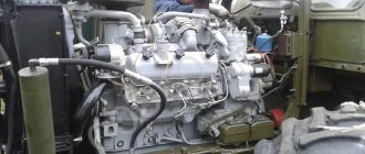
Engine A-01 in the Cheboksary Museum of Tractor History
The fuel pump is six-section, spool type, the lubrication system is combined.
Part of the diesel fuel from the power system is used to operate the electric torch air heating system in the intake manifold during diesel start-up in winter.
A manual fuel pump is used to fill the fuel supply system and remove air from it. In this case, the air is removed along with excess fuel into the fuel tank through the fuel drain line. Air is removed automatically along this same path when the A-01 diesel engine is running.
Engine lubrication system A-01
A-01 engines have a combined lubrication system, in which some parts are lubricated under pressure, and others by spraying oil. The oil container is the lower crankcase cover. To control the oil level, there is an oil gauge on the crankcase to the right of the oil filler pipe.
Oil from the lower crankcase cover is sucked by the oil pump through the oil intake. The oil pump has two outlets and, accordingly, creates two oil flows (dual flow oil pump).
One flow of oil, about 20 percent, is directed to the oil cooler and, after cooling, returns to the lower crankcase cover. The connection to the oil cooler is made by flexible oil lines.
The main oil flow is supplied to the oil filter. It passes in parallel through two filter elements. The purified oil enters the main oil line. From the main oil line, oil is supplied through channels to the bearings of the crankshaft, camshaft, intermediate gear, into the internal cavities of the pusher axles, and into the injection pump housing (if the injection pump has central lubrication).
From the axles of the pushers, oil flows through the channels of the pushers into the cavities of the rods, then to the rocker arms and rubbing pairs of the valve drive. The drive gears of the units, camshaft cams, cylinder liners, bearings of the upper connecting rod heads are lubricated by splashing oil. The oil pressure in the main oil line is maintained within acceptable limits by the oil pump pressure reducing valve and the oil filter drain valve.
When the oil pressure in the main flow is above 0.9…1.1 MPa (9…11 kgf/cm2), the oil pump pressure reducing valve transfers oil to the lower crankcase cover. The filter drain valve ensures that part of the oil is drained into the lower crankcase cover when the pressure at the filter outlet increases by more than 0.4...0.45 MPa (4...4.5 kgf/cm2).
A safety valve is installed in the radiator branch of the oil pump, which does not allow the oil pressure to increase above 0.25...0.32 MPa (2.5...3.2 kgf/cm2).
The oil filter also contains a bypass valve. It provides the necessary oil pressure when the filter elements are clogged, as well as during engine start-up with a large oil pressure drop across the filter, by transferring some of the unclean oil past the filter elements into the main oil line. This valve opens when the oil pressure drop across the filter is more than 0.15...0.19 MPa (1.5...1.9 kgf/cm2).
The engines are started by the PD-10U starting engine.
Crank mechanism. The crankcase is cast from cast iron. On the left side, a water distribution pipe is cast integrally with the block. Alignment of beds for main bearing liners
kov is ensured by boring them from one installation complete with covers. The seats for the main bearing caps are processed in such a way that there is no possibility of them turning over during assembly. On the right side of the cylinder block there are six inspection holes with a diameter of mm. Coolant leakage from the holes indicates damage to the seal of the lower flange of the liner of the corresponding cylinder.
The block head is cast from cast iron in one piece with the valve box. Two heads are installed on the engine, each of which is common to three cylinders. Each head is attached to the block with twenty studs through an iron-asbestos gasket. The gaskets must be installed with the wide side of the edging on the surface of the block, having previously lubricated their surface with graphite lubricant. The cylinder heads must be carefully aligned transversely, otherwise the mounting surfaces of the intake and exhaust manifolds will be in different timing gears.
The cylinder block pan is bolted through a cork gasket to the block, flywheel housing, crankcase and cover simultaneously.
The cylinder liners are cast from special cast iron. The inner working surface of the sleeve is subjected to high-frequency hardening to a depth of 1-2 mm. On the surface of the sleeve along the outer diameter there is a lower sealing belt with two annular grooves for sealing rubber rings. The upper seating belt of the sleeve is installed in the hole of the block with a slight interference fit.
Based on the internal diameter, the liners are divided into four groups. The group marking is applied on the upper end of the sleeve.
The pistons are cast from aluminum alloy. There is a recess on the bottom of the piston, which should be offset away from the camshaft. The piston has three grooves for compression rings and two for oil scraper rings. In a set of one engine, a difference in the weight of the pistons of up to g is allowed. The weight of the piston is marked with a three-digit number on the bottom. Depending on the outer diameter of the skirt and the diameter of the holes for the piston pin, the pistons are divided into groups.
The piston pin is a floating hollow steel type (made of steel grade 12ХНЗА). The working surface of the finger is cemented and polished. The fingers are divided into groups according to their outer diameter. The marking is applied with a stamp on the end part of the finger. The pin is held against axial displacement by retaining rings.
Piston rings are made of special cast iron. The upper compression ring is coated with a layer of porous chrome. Second section. The ring locks are straight. The gap in the lock of any ring when installed in the cylinder should be in the range of 0.45-0.65 mm. The two upper compression rings are installed on the piston with the conical surface facing up.
Both upper compression rings have a one-sided trapezoidal cross-section. The third compression ring is rectangular in cross-section. The oil scraper rings are rectangular
The connecting rods are stamped from 40X steel. A bushing made of OTSS-5-5-5 bronze is pressed into the upper head. According to the inner diameter of the upper head bushing, connecting rods are divided into three groups. The symbol of the group is applied to the end surface of the upper head of the connecting rod. The weight of the lower and upper heads of the connecting rod is also applied there. The number closest to the bottom head is the weight of the bottom head, and the other number is the weight of the top head. Weight in hundreds, tens and units of grams is indicated by two three-digit numbers.
The connecting rods included in the set for one engine should not differ in the weight of the upper and the weight of the lower heads by more than g. Adjustment by weight can be made by removing excess metal from the bosses of the connecting rod heads.
On one side of the connecting rod and its cover, matching marks and conventional serial numbers are applied, and on the other side - the cylinder number. The longitudinal play of the lower head of the connecting rod on the shaft journal is allowed within 0.17–0.44 mm.
The crankshaft is stamped from 50G steel. The shaft has six connecting rods and seven main journals. The plant produces and installs shafts of two production standards on engines. The symbol of the shaft and the mark are applied on the eleventh cheek.
The connecting rod journals of the shaft have cavities bored out for centrifugal oil purification, closed with threaded plugs.
On the toe of the crankshaft there are gears that drive the oil pump and camshaft, an oil slinger and a double-groove pulley. A splined bushing is mounted on pins in the bore of the crankshaft shank to drive an independent power take-off shaft.
The crankshaft is secured against axial displacements by thrust half-rings inserted into the bores of the seventh main bearing bed. The side of the half rings with grooves should be adjacent to the thrust ends of the shaft. The longitudinal play of the crankshaft should be 0.095–0.245 mm.
Bearing shells are made of bimetallic strip (lead bronze on a steel base). In accordance with the production and repair dimensions of the crankshaft, bearing shells are divided into groups, the designation of which is applied to the outer surface of the shell.
The flywheel is cast from gray cast iron grade SCh15-32. A roller bearing of the clutch shaft is installed in its bore. When installing the flywheel on the crankshaft, their “K” marks are aligned.
The gas distribution mechanism is overhead valve. The timing gears are located in the crankcase. The crankshaft gear and camshaft gear have letter marks that are aligned with the same marks on the idler gear during assembly. The gear is used to drive the fuel pump, and the gears are used to drive the hydraulic system pumps. A gear with a bronze bushing is mounted on a pin bolted to the block. The pin has drillings for oil supply. To control the supply of lubricant, there is a hole closed with a plug.
The camshaft is stamped from grade 45 steel. The shaft has seven journals and twelve cams, subjected to high-frequency hardening.
Pushers are roller type. Each pusher is a single-arm lever ending in a fork, in the hole of which a roller axis is installed. The pushers swing on an axle on bronze bushings. The axis of the pushers is hollow and is attached with supports to the engine block.
The rods are hollow steel. Tips with spherical hardened surfaces are pressed into the ends of the rods.
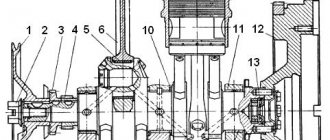
Rice. 1. Timing gears of the AM-01 engine.
The valves are made: inlet valves are made of EI-107 steel and exhaust valves are made of EI-69 steel with a welded tip made of 40ХН steel. The valve is pressed to the seat by two springs with different winding directions.
Rice. 2. Gas distribution mechanism of the AM-01 engine.
The decompression mechanism consists of two rollers with adjusting screws. The rollers are interconnected and located above the rocker arms. They can be turned using the control lever. When the lever is turned, the pressure screws rest against the ends of the rocker arms and open the valves slightly.
Rice. 3. Engine lubrication system AM-01.
The AM-01 engine lubrication system is combined.
The oil pump is a two-section gear type with pressure reducing and safety valves. The pressure section of the pump provides oil supply to the engine, and the radiator section provides
The pump is driven from the crankshaft gear through an idler gear. Performance of pump sections at 3100 rpm. The pump drive roller is 105 l/min for the injection pump and l/min for the radiator pump. The oil pressure at the outlet should be within the following limits: for the discharge section - 6-7 kg/cm2 and for the radiator section - 0.3-0.7 kg/cm2.
Rice. 4. Water pump and engine fan AM-01.
The pressure reducing valve serves to limit the oil pressure of the discharge section. The safety valve of the radiator section prevents damage to the oil cooler during engine starting and when the radiator is faulty (contamination).
The valves must be adjusted to the pressure: pressure relief - 7.5 ± 0.5 kg/cm2 and safety - 0.8-1.2 kg/cm2.
The coarse oil filter has two filter elements with a cylindrical corrugated frame on which a brass mesh is wound. A bypass valve is installed in the coarse filter housing, allowing oil to flow into the main oil line when the filter is dirty or when the oil is cold. On the way the oil exits from the coarse filter into the main oil line, a drain valve is installed in a special attachment, adjusted to a pressure of 3.5-5 kg/cm2.
The centrifuge provides fine purification of the oil, after which it flows into the engine sump.
The oil cooler switch is used to turn it on in summer and turn it off in winter. The switch is installed in the crankcase boss. To turn the radiator on or off, it is necessary to loosen the fitting of the oil supply tube, unscrew the bolts securing the switch and turn it until the letter “L” or “3” coincides with the arrow on the block. The switch is equipped with a valve to automatically disconnect the oil cooler from the lubrication system. The valve is adjusted to a pressure of 1.6-1.8 kg/cm2 and works only when the switch is set to the “L” position. In position "3", oil passes through the switch into the engine sump. The oil temperature in the crankcase is controlled by a thermometer, and the pressure in the line is controlled by a pressure gauge.
The cooling system is a closed type with forced water circulation. When filling the system, it is necessary to unscrew the bolt plug on the water pump housing to remove air from the cooling system.
The water pump and fan are mounted as a common unit. The pump shaft is mounted in a housing on two bearings. At the front end of the shaft there is a pulley with a fan impeller, and at the rear end there is a pump impeller. The pulley is driven by two V-belts from the crankshaft. One of the belts is the drive belt for the generator. The tension of this belt is carried out by changing the position of the generator. The second belt is tensioned using a tension roller mounted in the gear housing cover.
Supply system. The fuel is subjected to three-stage cleaning: in a settling filter, in a filter with two fine paper filter elements TF-2, and in a control filter with one TF-2 element. In addition, the fuel passes through a strainer in each injector.
Rice. 5. AM-01 engine power supply system.
The booster pump is piston type. It is driven by the cam of the high pressure fuel pump and a manual fuel pump.
The fuel pump is a high-pressure six-piston type. It is equipped with an all-mode speed controller. The pump has a corrector that provides additional fuel supply at maximum engine load.
Nozzles are multi-nozzle closed type. They are connected by high pressure pipelines to the pump. The sprayer has four holes with a diameter of 0.32 mm. The nozzles are adjusted to a spray start pressure of 150 kg/cm2. The needle lift when injecting fuel into the cylinder is 0.4-0.5 mm. The injector is equipped with a fine fuel filter.
Air cleaner - multicyclone type. double air purification. The first stage is a housing with a hopper and a section with assembled cyclones welded to it.
The second stage is made in the form of cassettes made of wire gimp moistened with oil. The first stage hopper is connected by a pipeline to an ejector on the engine exhaust pipe, due to which during operation there is a continuous suction of dust from the hopper into the surrounding atmosphere.
Cooling system and air supply system
A-01 diesel engines are equipped with a closed-type liquid cooling system with forced circulation of coolant. The circulation of the coolant is ensured by a centrifugal pump. Under pressure, it drives coolant through the liquid fluid pipes (if equipped), cooling the engine oil. Then the liquid enters the crankcase cooling jacket, cooling first the lower part of the cylinder liners, and then the upper (more heated) part.
From the upper zone, the coolant enters the cooling jackets of the cylinder heads, first going to the hottest locations of the exhaust valves and injectors. From the cylinder head cooling jackets, the liquid collects in a water pipe and goes to the thermostat box. The thermostat speeds up the warm-up of the diesel engine and regulates the coolant temperature within acceptable limits. The diesel cooling system has places for connecting the cabin heater and pre-heater.
The engine is supplied with the air necessary for the combustion of diesel fuel in the cylinders by self-suction, under the influence of vacuum, which is created by the movements of the pistons on the intake strokes.
Electrical system
The electrical equipment system of A-01 diesel engines has a single-wire design. The electrical equipment of these motors is designed for a 24 Volt network voltage.
The electrical system also includes: a generator designed to work in conjunction with the battery as a source of electricity; starter used for direct electric starting of the engine; flare plug for the electric torch heating system (EFH) of air in the intake manifold; fuel valve for the EFP system; electromagnetic fuel valve (KET) for emergency stop of the engine when the oil pressure drops below the permissible level; fuel filter clogging sensor; air filter clogging sensor.
Maintenance and repair
Maintenance of the A01 motor is quite simple. We can say that it is similar to all diesel power units, such as YaMZ. Maintenance is carried out every 12-15 thousand kilometers. This indicator includes changing the engine oil and filter element. It is also recommended to check the ignition and the condition of the air filter. Do not forget that the air element is replaced every second maintenance.
The engine is not particularly demanding in the use of fuel and engine oil. So, for normal operation any more or less high-quality mineral lubricant is suitable. As practice shows, motorists usually pour oil such as M10 into the engine. It perfectly performs all the necessary functions, and also, if replaced in a timely manner, protects the engine elements well. It is recommended to pay special attention to the air filter. It is best to take a quality product with a metal base.
Starting motor, hydraulic equipment
The A-01 engine is equipped with a starting carburetor two-stroke engine model PD-10U, with electric start.
Also on the A-01 engine are two hydraulic pumps: NSh-10DL (with a capacity of 14.5 liters per minute) and NSh-32 or NSh-50 (with a capacity of 70 liters per minute), gear-type, driven by the crankshaft. The pump drive is switchable.
Technical characteristics of the A-01 engine in numbers
- The operating order of the cylinders is: 1-5-3-6-2-4.
- Cylinder diameter – 130 mm.
- The piston stroke is 140 mm.
- The working volume of the cylinders is 11.15 liters.
- Compression ratio: 16.5±0.5.
- Mixture formation method: direct injection of diesel fuel.
- Rated power – 99 kW (135 hp)
- Rated crankshaft speed: 1700 min-1.
- The nominal torque reserve factor is 25 percent.
- The specific effective consumption of diesel fuel at rated power is no more than 221 g/kWh (163 g/l.s.h).
- Relative oil consumption for waste, % to fuel consumption – no more than 0.3 percent.
Engine a01 cylinder operating order
The A-01M engine is the base model. It is installed on the T-4A tractor and its modifications, motor graders DZ-122, DZ-143, DZ-180, excavators EO-4121, EO-4124, MTP-71A, MTP-72, feller buncher LP-19A, pneumatic rollers DU-58, DU-62
Direction of rotation of the crankshaft (fan side)
Right (clockwise)
Rated power, kW (hp)
Operating power, kW (hp)
Rated crankshaft rotation speed, rpm
Maximum crankshaft rotation speed at idle speed, no more, rpm
Maximum stable crankshaft rotation speed at idle, no more than, rpm
Maximum torque at 1100-1300 rpm, not less, N.m (kgf.m)
Installation angle of fuel injection advance, degrees.
Limit angles of inclination of the diesel engine, degrees, not less:
Specific fuel consumption at rated power, no more, g/kWh (g/hp.h)
Specific fuel consumption at operating power, no more than, g/kWh (g/hp.h)
Modifications of the A-01 engine
- A-01M, A-01MI – basic model, overall dimensions 1777 x 825 x 1423 mm.
- A-01MSI - with a thermostat and a two-speed gearbox of the starting motor, overall dimensions 1777 x 739 x 1443 mm.
- A-01MB – hydraulic pumps and drives to them are not installed. Overall dimensions 1777 x 825 x 1423 mm.
- A-01MK – not installed: clutch, hydraulic pumps and drive to them. Overall dimensions: 1678 x 825 x 1423 mm.
- A-01MKS , A-01MKSI - installed: electric starter, thermostat. Not installed: clutch, hydraulic pumps and drive to them. Overall dimensions: 1630 x 739 x 1443 mm.
- A-01MS – installed: electric starter, thermostat, spark plug, fuel valve. Overall dimensions: 1630 x 739 x 1443 mm.
- A-01MR , A-01MRI - the following are installed: a thermostat, a two-speed gearbox of the starting motor. Overall dimensions: 1777 x 825 x 1423 mm.
- A-01ME – not installed: hydraulic pumps and drive to them, clutch, decompressor mechanism. Overall dimensions: 1630 x 739 x 1443 mm.
- A-01MES – an electric starter is installed. Not installed: hydraulic pumps and drive to them, clutch. Overall dimensions 1630 x 739 x 1443 mm.
The A-01M engines used liners made of special cast iron with the working surface treated by flat-top honing, pistons with a three-ring set of piston rings, an optimized side surface profile and a graphitized skirt, a crankcase with increased strength and improved cooling of the cylinder liners.
Improvements in the design of diesel engines made in recent years have made it possible to reduce engine oil consumption due to waste and increase engine life to 12 thousand engine hours.
Applicability of the A-01M engine: motor graders DZ-122, DZ-143, DZ-180, excavators EO-121, EO-4124, road pavers DU-58, DU-62, tractors TT-4, TT-4M, T-4A .
Applicability of the A-01MI engine: motor graders DZ-122, DZ-143, DZ-180, excavators EO-121, EO-4124, road pavers DU-58, DU-62, tractors TT-4, TT-4M, T-4A
Applicability of the A-01M, A-01MK engine: front loaders TO-18, TO-29.
Applicability of the A-01MKI, A-01MKS, A-01MKSI engine: TO-18, TO-28 front loaders.
Applicability of the A-01MR, A-01MRI, A-01MRS, A-01MRSI (engine with a false sump), A-01MS: motor graders DZ-122, DZ-143, DZ-180, excavators EO-121, EO-4124, road pavers DU-58, DU-62, tractors TT-4, TT-4M, T-4A.
Engine applicability: motor graders DZ-122, DZ-143, DZ-180, excavators EO-121, EO-4124, road paver DU-58, DU-62, tractor TT-4, TT-4M, T-4A
The main design measures introduced on diesel engines of the Altai Motor Plant in the 2000s:
- only individual cylinder heads were used, instead of monoblock ones, due to which an increase in the reliability of the gas joint seal was achieved, a decrease in the ovalization of the cylinder liner, and a decrease in crankcase oil consumption for waste;
- an electric starter was introduced (instead of a starting engine with a gearbox);
- a block crankcase made of castings from Luitpoldhuette, Germany was used with a modified cooling circuit, due to which reliability was increased and efficient cooling of the cylinder liners was ensured.