- home
- Media center
- Articles
- Oil volume in the ZIL 131 engine
Menu
- News
- Articles
- Video materials
- Photo materials
- Publication in the media
- 3D tour
26.11.2020
ZIL 131 is a truck created by the Likhachev Moscow Automobile Plant. Years of production: 1966-2002. The truck was distinguished by increased cross-country ability, so it was originally created for military purposes. Previously it had a body with a cargo platform made of wood. The tailgate can be folded back for convenience.
Also based on the truck, tanks for transporting fuel, fire trucks with a tank and some other special vehicles for various purposes were produced. Now the car is not produced, but many copies of this model are still in use in a number of countries from around the world.
ZIL was equipped primarily with a 6-liter gasoline engine with a power of 150 horsepower. Fuel consumption in the combined cycle is at least 35.5 liters per 100 kilometers. The maximum speed of a truck usually does not exceed 80 km/h. The manufacturer recommended AI-76 gasoline for this model. But today cars are usually filled with AI-80 fuel.
Oil volume in the ZIL 131 engine
ZIL 131 is a truck created by the Likhachev Moscow Automobile Plant. Years of production: 1966-2002. The truck was distinguished by increased cross-country ability, so it was originally created for military purposes. Previously it had a body with a cargo platform made of wood. The tailgate can be folded back for convenience.
Also based on the truck, tanks for transporting fuel, fire trucks with a tank and some other special vehicles for various purposes were produced. Now the car is not produced, but many copies of this model are still in use in a number of countries from around the world.
ZIL was equipped primarily with a 6-liter gasoline engine with a power of 150 horsepower. Fuel consumption in the combined cycle is at least 35.5 liters per 100 kilometers. The maximum speed of a truck usually does not exceed 80 km/h. The manufacturer recommended AI-76 gasoline for this model. But today cars are usually filled with AI-80 fuel.
Short description
The ZIL 130 (508) engine was installed on ZIL-130 and ZIL-131 trucks. The design of the ZIL 130 engine had many similarities with the engine of the executive model ZIL-111, but in general the engine models had a low degree of unification. The engine volume was reduced to 6 liters, a two-chamber carburetor was installed and it was equipped with a speed limiter. Seven-liter engines are called ZIL-375 and are used in trucks of the Ural Automobile Plant. The increase in volume was achieved by increasing the radius of the cylinders to 108 mm, while maintaining the piston stroke of 95 mm.
Refueling volumes of ZIL 131
In order to properly maintain the car and change consumables on time, you need to know the volume of fluids for the ZIL 131 car.
The oil volume in the ZIL 131 engine is 9.5 liters. At temperatures down to -30 degrees Celsius, it is recommended to fill it with M-6/10B liquid. It can be used all year round in regions where the thermometer does not fall below this mark. For areas with cold climates, where temperatures often drop below 30 degrees in winter, it is advisable to use M-4/6B engine oil.
- The volume of ZIL 131 oil may also imply transmission fluid. Its quantity in the car’s gearbox is 5.1 liters. The oil in the ZIL 131 box should be filled with TSp-15K. It is considered all-season and is suitable for use in winter in most Russian regions. But where the temperature drops below 30 degrees, in winter it is advisable to use a liquid with the characteristics of TSp-10.
- In ZIL 131, the coolant volume is 29 liters. For the cooling system, you can use Antifreeze A-40. It is also permissible to use water in the summer.
- The car is equipped with two fuel tanks. Each of them holds 170 liters of gasoline. The hydraulic steering system requires 3.2 liters of oil with index P.
- 3.3 liters of TSp-15K lubricant is poured into the transfer case. It is the same as for the gearbox. At temperatures below 30 degrees Celsius, it is advisable to use chemistry with the characteristics of TSp-10.
- For winch gear housings and final drive housings of automobile drive axles, TSp-15K transmission oil should be used. In winter, if the temperature often drops to -30 degrees or below, you need to fill in chemicals with the TSp-10 index.
These oils are now produced by different manufacturers. They have a similar composition and almost identical properties. Therefore, you can buy chemicals of any brand, based on its affordability and availability.
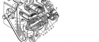
The oil filter for purifying the oil of the ZIL-131 engine is the same in design as that of the ZMZ-66 engine, and is distinguished by the presence of a bypass ball valve designed to bypass the oil, bypassing the filter in case of significant wear of the engine crankshaft bearings.
The oil cooler switch valve is screwed into the housing of the lower section of the oil pump. To monitor the oil level, a level indicator is installed on the left side of the engine, on which there are three marks: “Fill”, “Full” and a mark in the form of a rectangle above the “Full” mark. When parking the car for a long time before starting the engine, the oil level should be within the rectangular mark. The pressure in the lubrication system is controlled by a control lamp and a pressure gauge.
The operation of the lubrication system is as follows. The upper section of the oil pump supplies oil through a channel in the rear partition of the block to the filter. The purified oil enters the distribution chamber located in the rear partition of the block, from where it enters two longitudinal main channels. From the left channel it is supplied to the main bearings of the crankshaft, and from them to the bearings and thrust flange of the camshaft. It flows through channels in the crankshaft to the connecting rod bearings. There is a hole in the connecting rod body, at the moment of which it coincides with the channel in the crankshaft journal, oil is sprayed onto the cylinder wall. Through two radial holes in the journal of the middle camshaft bearing, oil is periodically supplied through channels in the cylinder block, cylinder heads, struts, and rocker arm axles to the rocker arm bushings, and through the holes in the rocker arms to the upper tips of the rods. The pushers are lubricated with oil from the longitudinal main channels.
Rice. 1. Diagram of the ZIL-130 engine lubrication system: 1 - oil sump; 2 — oiliriemnnk; 3 — oil radiator valve; 4 - oil pump; 5 - oil distribution chamber; 6—oil purification filter (centrifuge); 7 — air filter; 8 - compressor; 9, 14 — left and right main channels; 10, 11 — tubes for supplying and draining oil from the compressor; 12— oil cooler; 13 - cavities of the connecting rod journals (traps) for centrifugal oil purification
Rice. 2. Crankcase ventilation diagram of the ZIL-131 engine: 1 - crankcase ventilation air filter and oil filler neck; 2 - oil catcher; 3 - ventilation valve; 4— fitting; 5 - valve body
From the front end of the right main channel, oil is supplied to lubricate the compressor, and from it flows through a pipeline into the crankcase. Oil is supplied to the radiator by the lower section of the pump through a tap. The pressure in the system should be 2-4 kgf/cm2.
Crankcase ventilation is forced and is carried out by suction of gases from the crankcase through a valve. The valve is designed to regulate the amount of gases depending on the operating mode of the engine. The crankcase ventilation system operates as follows. When the engine is idling, the ventilation valve rises due to the high vacuum in the intake manifold, and the flow area of the fitting decreases - a small amount of gases is sucked into the intake manifold. With an increase in the opening of the carburetor throttle valves when the engine is running under load, the vacuum in the intake manifold decreases, the valve lowers under the influence of its own weight, and the flow area between it and the fitting increases, which corresponds to the passage of a larger volume of gases breaking into the crankcase. Before the valve, at the exit from the internal space of the engine, crankcase gases pass through a special oil trap, which prevents oil and gases from entering the combustion chamber. Fresh air enters the crankcase through a filter installed on the oil filler pipe. To turn off the ventilation system when fording, a tap is installed between the tubes. The crane handle must be positioned vertically when fording.
When to change the oil in the ZIL 131 engine?
The manufacturer recommends changing the lubricant in the power unit every 8-15 thousand kilometers. But if the car is used in difficult conditions, often drives on rural dirt roads or sits idle in city traffic jams, replacement must be done more often. The same applies to the age of the car. Now all ZILs are far from new, so such maintenance should be carried out approximately every 4,000 kilometers.
The oil must be changed together with the filter. Sometimes the fluid needs to be replaced ahead of schedule. This must be done in the following cases:
- Filled with obviously low-quality liquid.
- Overhaul or other work was carried out to restore the engine.
- The oil has an excessively dark color and foreign impurities.
- Insufficient amount of chemicals in the engine (in this case, topping up is possible).
Dimensional and weight characteristics of ZIL-4331
The car is relatively compact, its dimensions today allow it to be used in city conditions - most road structures will not become an obstacle in the way of this truck:
The wheelbase is also quite short for a car of this size:
The ground clearance can please even the most demanding drivers and those who carry out transportation on extremely poor roads: its value is as much as 330 mm. The average track width is 1,930 mm.
The weight of the car itself is 4,820 kg (excluding refueling fluids). The maximum load that the ZIL-4331 can carry is 6,000 kg.
Thus, this truck cannot seriously compete with foreign analogues due to its rather high fuel consumption and low load capacity. But the ease of repair and low cost make the car in question extremely popular.
The total weight of the ZIL with a full load and filling fluids is approximately 11,700 kg.
This weight can easily withstand most of the various bridges and other similar engineering communications on the roads.
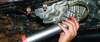
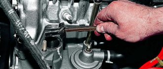
Features of oil change in ZIL 131
The oil in the power unit of the 131st is changed according to the following algorithm:
- Warm up the engine to operating temperature.
- Wait a few minutes for the power unit to cool down slightly. This will make working easier and safer.
- Take a container for waste liquid and place it under the drain hole.
- Unscrew the cover located under the crankcase. You need to unscrew it with a key and then with your hands.
- Drain off old chemicals. During draining, it is necessary to evaluate the condition, color and presence of impurities. If there are a lot of foreign particles in the oil, the engine may need to be flushed. In other cases, you can do without this procedure. Usually the liquid drains in about five minutes. It is impossible to remove it entirely from the power unit, but this does not harm it at all.
- Add new fluid and replace the filter element.
When pouring liquid, you need to control the volume using a dipstick. It is recommended that the quantity be between the minimum and maximum. This is approximately 90% of the desired value. Then the chemistry can be topped up to the limit. Upon completion of work, check the volume again. This method helps not to overfill the oil and avoid underfilling it.
Despite the fact that the engine of this truck is reliable and unpretentious, it cannot be operated with insufficient volume or with old oil or filter. This reduces the service life of the motor and leads to the need for major repairs. Therefore, it is necessary to adhere to the prescribed replacement deadlines. When carrying out the procedure, it is necessary to install a new filter element.
Source
Refueling volumes and recommended operating materials ZIL-131
| Filling/lubrication point | Volume, l | Name of material/liquid |
| Fuel tanks | 2x170 | Gasoline A-76 |
| Cooling system | 29 | Antifreeze A-40 (water allowed) |
| Engine lubrication system | 9 | All-season up to minus 30°C - oils M-6/10V (DV-ASZp-YuV) and M-8V, at temperatures below minus 30°C oil ASZp-6 (M-4/6V,) |
| Hydraulic steering system | 3,2 | Oil grade P |
| Gearbox (without power take-off) | 5,1 | All-season oil TSp-15K, at temperatures below minus 30°C oil TSp-10 |
| Transfer case | 3,3 | All-season oil TSp-15K, at temperatures below minus 30°C oil TSp-10 |
| Main gear housings for driving axles | 3×5,0 | All-season oil TSp-15K, at temperatures below minus 30°C oil TSp-10 |
| Winch gear housing | 2,4 | All-season oil TSp-15K, at temperatures below minus 30°C oil TSp-10 |
| Shock absorbers | 2×0,45 | Shock-absorbing fluid AZh-12T |
Order a book on repair and operation www.zamenafiltra.com
Replacing the oil filter
Some drivers think, why and is it necessary to replace the oil filter while filling engine oil? Experts need to answer! In car services, the filter is usually changed before adding engine oil. Additionally, it is necessary to lubricate the sealing gasket on the filter housing with oil.
Under no circumstances should the engine be allowed to be operated with an old filter. If the filter is clogged, engine oil flows past it. The oil filter becomes clogged after 10-14 thousand kilometers.
Didn't find the information you are looking for? on our forum.
Engine ZIL-131: 645, technical characteristics, volume, oil, where the number is located
The ZIL-131 engine is a unit that is produced by the Likhachev plant. This node is responsible for converting energy into mechanical work.
Device
This vehicle comes with a diesel engine and a liquid cooling system.
The power unit structure includes the following components and mechanisms:
- hydraulic power steering pump element;
- pump tank;
- fan;
- filter element for crankcase ventilation of an internal combustion engine;
- air filter;
- a filter mechanism designed to clean oil fluid;
- ignition system switchgear;
- electric starter;
- generator set;
- pre-heater boiler;
- clutch mechanism;
- carburetor;
- cylindrical elements;
- power take-off box;
- Transmission;
- heating device fuel tank;
- compressor and sprayer;
- ICE fasteners.
The motor is attached to the support frame at three points. The front support mechanism is a bracket located under the timing gear cover. The rear support is presented in the form of claws of the coupling mechanism housing. Between the bracket and the front cross member of the support frame there are round cushions made of rubber.
All pillows are interchangeable, i.e. Pillows from the front support can be placed on the back and vice versa. The power unit is also connected to the front cross member of the frame using a reaction-type rod, on which rubber shock absorbers are installed.
Reaction type traction is used to keep the motor from longitudinal movement when the clutch is disengaged and the transfer case is engaged or while the vehicle is braking.
The engine suspension mechanism includes: front and rear mount, thrust buffer, connecting rod, bracket, mounts and mounting bolts.
The number is located on the tide of the block near the compressor, where the mounting eye is screwed in.
Cooling system
The design of the ZIL-131 engine cooling system consists of:
- radiator;
- water pump;
- traffic jams;
- pre-start hose;
- thermostat;
- heating device tap;
- tubes;
- a sensor that reflects the temperature readings of the power unit;
- power crane;
- crane drive;
- outlet tube.
When the engine is warm, coolant flows from the radiator into the water pump element. Under pressure, it moves through two discharge pipes and enters the left and right block of cylindrical elements. Moving through the windows in the inter-cylinder partitions, the liquid cools the heads of the cylindrical parts.
After this, the working fluid continues its longitudinal movement from the rear end of the cylinder heads to the front. Then it enters the thermostat pipe and the radiator, passing through the channels of the intake pipe.
Before filling the bearing cavities of the water pump mechanism with lubricant, it is recommended to unscrew the plug that covers the inspection hole.
Refilling should be carried out until fresh oil fluid appears from the inspection hole, after which the screw plug can be replaced.
The fan and water pumping device must be driven from the crankshaft pulley using two belts. At this time, the front belt mechanism should cover the generator set pulley, and the second should cover the hydraulic power steering pump pulley.
Maintenance of ZIL-131 bridges
It is necessary to regularly add grease to the axles and replace it as indicated in the lubrication chart
Oil must be poured into the crankcases of all axles of the vehicle through the filler (inspection) hole located in the upper wall of the gearbox housing, closed with plug 29, until oil leaks from the open inspection hole.
In addition to the filler hole, you can add oil to the front axle crankcase through the control hole located in the axle crankcase cover.
The oil level in the rear and middle axles should be checked during operation using a special level indicator 1 (Fig. 1) available in the tool kit.
To check the oil level in the rear and middle axles, you need to unscrew the bolt shown in Fig. 1, attach the gearbox to the axle housing and insert the oil level indicator into the bolt hole until it stops against the gearbox housing flange.
The correct oil level is indicated by a mark on the oil level indicator stem.
When the oil level drops below the mark, it is necessary to add oil to the crankcase to the level of the control plug.
To drain used oil from the front axle housing, there is a drain hole 48 (Figure 2), located in the lower part of the axle housing.
The drain holes for the rear and middle axle crankcases are located at the bottom of the crankcase covers.
In addition, there are additional drain holes for removing residual oil from the gearbox housings: a hole with plug 30 (Figure 3), located in the lower wall of the front axle gearbox housing, and holes with plugs 36 (Figure 4), made in the front walls of the rear axle gearbox housings and middle bridges.
Figure 4
Drain the used oil after preheating the unit through all available drain holes.
The inspection holes must be open.
If necessary, add grease to the steering knuckle housing for the king pin bearings and the front drive axle axle joint.
It is necessary to fill the lubricant in a heated state through grease nipples 17 (Figure 5), located in the upper lining of the right steering knuckle housing and in the swing arm mounted on the left steering knuckle housing; you need to fill it until the lubricant begins to come out through the control hole located at the bottom of the ball joint.
Figure 5
Plug 27, which closes this hole, must first be unscrewed.
When changing the lubricant, all parts of the steering knuckle and the axle shaft joint must be washed.
Fresh lubricant is placed directly inside the ball joint, in the king pin bearings and in the axle joint.
The wheel hub must also be washed when changing.
When adding fresh grease, the bearings must be thoroughly lubricated.
Tightening torques for bolted connections in kgm
Nuts of bolts securing differential cups and driven cylindrical gear 12—14
Nuts of studs securing differential bearing caps 17—19
Studs for fastening differential bearing caps (when installed in the gearbox housing) 22—25
Bolts for fastening the gearbox roller bearing covers - 6—8
Bolts securing the gearbox to the axle housing - 9—11
Nuts of the studs securing the axle shafts of the rear and middle axles, flanges of the axle shafts of the front drive axle to the wheel hubs 7—9
Nuts of studs securing the steering knuckle lever to the body and studs securing the ball joint to the front axle housing ... 16—18
Nuts of the studs securing the axles of the front, rear and middle axles 5.5—6
Nuts for fastening the shaft flanges of the drive bevel gear 20—25
Nut for securing the shaft bearing of the drive spur gear 35—40
Lock nut for securing wheel hub bearings 12—15
Tie rod ball pin fastening nut 23—27
Axle breathers should be regularly cleaned of dirt.
Breathers for communicating the internal cavity of the axle housing with the atmosphere are located in the upper walls of the bridge beams: on the front axle - to the left (along the route) of the gearbox, on the rear and middle axles to the right (along the route) of the gearbox.
Figure 6
In addition, there are additional breathers 19 (see Figure 6) for air release in the event of a malfunction of the oil seals of the heads 22 for supplying air to the wheel tires.
These breathers are located: on the front axle in the steering knuckle housings, above the steering linkage arms, on the rear and middle axles - in the end flanges of the axle housings.
The appearance of grease from the holes of these breathers indicates an air leak from the tire pressure control system.
The cause of the leak must be found and eliminated. If there is a leak, it is necessary to replace the air supply heads to the tires.
You should check that there is no oil leakage through the seals and flange connections.
Faulty oil seals and sealing gaskets must be replaced, and the bolts and nuts of flange connections must be tightened in a timely manner.
It is necessary to constantly monitor the tightness of the bolted connections, especially the gearbox mounting bolts, the nuts that secure the axle shafts to the wheel hubs, the nuts that secure the ball joint to the axle housing flange, and the nuts that secure the steering knuckle arm.
We must remember that two of the twelve gearbox mounting bolts are located inside the gearbox housing. In order to tighten them, you must first remove the cover 26 of the gearbox housing.
Each time you remove the brake drums, you need to tighten the trunnion nuts.
When assembling bridges, the following requirements must be met to ensure tightness when a vehicle crosses fords:
1) all flange connections, both those with sealing gaskets and those without gaskets, must be lubricated with sealing paste during assembly;
2) before installation, steel adjusting shims must be washed and lubricated with spindle oil (GOST 1642-50) or other similar liquid oil;
3) thin shims should be installed on both sides of the shim set;
4) control plug 27 of the drain hole (see Figure 5) of the ball joint must be lubricated with UN-25 paste before installation.
The axle shafts must be removed and inserted very carefully so as not to damage the sealing seals and rubber seals of the air supply head to the wheel, located inside the axles.
Before installing the axle shafts of the rear and middle axles, the journals of the axle shafts under the oil seals and under the air supply heads must be lubricated with the lubricant specified in the lubrication chart for wheel hub bearings. The thickness of the lubricant layer is 1-1.5 mm.
The axle shafts of the front drive axle must have lubricated journals under the oil seals.
Before replacing the steering knuckle axle of the front drive axle and the crankcase axles of the rear and middle axles, the working surfaces of the cuffs and the surfaces of the centering holes of the air supply heads must be lubricated with a thin layer of the same lubricant.
The internal cavity of the air supply head must be filled with lubricant; in this case, the hole for the fitting must be free of grease.
For the front drive axle, in addition, the journals under the air supply head and under the bronze bushing at the knuckle joints of the axle shafts must be lubricated.
Internal cavity " a
"(see figure) the axle shaft seal races and the space "
b
" between the air supply head and the support ring must also be filled with lubricant.
For the rear and middle axles, the following must be filled with the specified lubricant: space “a” (see Figure 6) between the air supply head and the oil seal protective sleeve, space “ b
" between the axle shaft seal and the crankcase support flange, as well as the cavity "
in
" between the flanges of the axle and the axle housing.
When installing the trunnions in place, it is necessary to ensure the correct position of the air supply holes in the journals of the trunnions.
The hole should be directed:
a) for the front axle - up and back, behind the second axle mounting pin from the vertical;
b) for the middle bridge - up and back, behind the first pin from the vertical;
c) for the rear axle - up and forward, behind the first stud from the vertical.
Assembling and disassembling the hinges of the axle shafts of the front drive axle is carried out with some effort when installing and removing the drive ball and requires special skill, therefore the hinge should be disassembled only if particularly necessary and this should be done in a workshop.
When disassembling, you should mark with chalk or paint the relative positions of the driving and driven forks and driving balls, and when reassembling, install all the parts in the same relative position that they had before disassembling.
To facilitate the removal of the axle shafts of the rear and middle axles and the removal of the flange of the hinge knuckle of the axle shaft of the front drive axle, puller bolts are used, wrapped in the flanges of the axle shafts and locked with locknuts.
For the same purpose, holes with M12 threads (pitch 1.75 mm) are made in the flanges of the following parts: steering knuckle axle; ball joint of the steering knuckle; beam axle of the rear and middle axles; bearing housing for the drive bevel gear of the gearbox; bearing seat of the driven bevel gear of the gearbox.
As a puller for these parts, you can use any fastening bolt with M12 thread (pitch 1.75 mm), used for fastening bridge parts.
Removing the top cap of the kingpin bearings mounted on the steering knuckle housing is made easier by tapping it with a hammer from the side, on an untreated surface.