The internal combustion engine has supplanted other types of power plants, however, work aimed at eliminating the use of these units suggests an imminent change in leading positions.
Since the beginning of technological progress, when the use of engines that burned fuel internally was just beginning, their superiority was not obvious. A steam engine, as a competitor, contains a lot of advantages: along with traction parameters, it is silent, omnivorous, easy to control and configure. But lightness, reliability and efficiency allowed the internal combustion engine to take over steam.
Today, issues of ecology, efficiency and safety are at the forefront. This forces engineers to focus on production units powered by renewable fuel sources. In the 16th century, Robert Stirling registered an engine powered by external heat sources. Engineers believe that this unit is capable of replacing the modern leader. The Stirling engine combines efficiency, reliability, runs quietly, on any fuel, this makes the product a player in the automotive market.
Robert Stirling (1790-1878):
History of the Stirling engine
Initially, the installation was developed to replace a machine powered by steam. Boilers of steam mechanisms exploded when the pressure exceeded permissible standards. From this point of view, Stirling is much safer; it operates using temperature differences.
The principle of operation of the Stirling engine is to alternately supply or extract heat from the substance on which work is being done. The substance itself is enclosed in a closed volume. The role of the working substance is performed by gases or liquids. There are substances that act as two components; gas is converted into liquid and vice versa. The Stirling liquid piston engine is small in size, powerful, and produces high pressure.
The decrease and increase in the volume of gas during cooling or heating, respectively, is confirmed by the law of thermodynamics, according to which all components: the degree of heating, the amount of space occupied by the substance, the force acting per unit area are related and described by the formula:
Application area
Stirling engines operating from an external heat source can be used for the manufacture of:
- Generators. Using a power unit, you can convert thermal energy into electrical energy. This is very convenient in places where the electricity supply is intermittent or absent;
- Pumps for pumping various liquids. The power of the power plant is sufficient for pumping various liquids;
- Climatic equipment;
- Cars and self-propelled equipment.
The simplicity of the design allows the power units to be used to create cars and various equipment. Operation on any fuel allows the use of such motors in places where the power supply is intermittent or absent.
Engine operating principle
To understand how a Stirling engine works, let’s understand the structure and frequency of the unit’s phenomena. The mechanism converts the heat received from the heater located outside the product into a force on the body. The whole process occurs due to a temperature difference in the working substance located in a closed circuit.
The principle of operation of the mechanism is based on expansion due to heat. Immediately before expansion, the substance in a closed loop is heated. Accordingly, before being compressed, the substance is cooled. The cylinder itself (1) is enveloped in a water jacket (3), and heat is supplied to the bottom. The piston doing the work (4) is placed in a sleeve and sealed with rings. Between the piston and the bottom there is a displacement mechanism (2), which has significant gaps and moves freely. The substance, located in a closed loop, moves throughout the chamber volume due to the displacer. The movement of matter is limited in two directions: the bottom of the piston, the bottom of the cylinder. The movement of the displacer is provided by a rod (5), which passes through the piston and operates due to an eccentric with a delay of 90° in comparison with the piston drive.
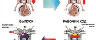
- Position "A":
The piston is located in the lowest position, the substance is cooled by the walls.
- Position "B":
The displacer occupies the upper position, moves, passes the substance through the end slots to the bottom, and cools itself. The piston remains motionless.
- Position "C":
The substance receives heat, under the influence of heat it increases in volume and lifts the expander with the piston upward. The work is done, after which the displacer sinks to the bottom, pushing out the substance and cooling.
- Position "D":
The piston goes down, compresses the cooled substance, and useful work is performed. The flywheel serves as an energy accumulator in the design.
The considered model does not have a regenerator, so the efficiency of the mechanism is not high. The heat of the substance after work is done is transferred to the coolant using the walls. The temperature does not have time to decrease by the required amount, so the cooling time is prolonged and the motor speed is low.
Cycle
The Stirling external combustion engine uses the same set of phenomena. The effect of the ongoing action in the mechanism is high. Thanks to this, it is possible to design an engine with good performance within normal dimensions.
It must be taken into account that the design of the mechanism includes a heater, a refrigerator and a regenerator, a device that removes heat from the substance and returns the heat at the right time.
Ideal Stirling cycle (temperature-volume diagram):
Ideal circular phenomena:
- 1-2 Change in the linear dimensions of a substance with constant temperature;
- 2-3 Heat removal from the substance to the heat exchanger, the space occupied by the substance constantly;
- 3-4 Forced reduction of the space occupied by the substance, the temperature is constant, heat is transferred to the cooler;
- 4-1 Forced increase in the temperature of a substance, the occupied space is constant, heat is supplied from a heat exchanger.
Ideal Stirling cycle (pressure-volume diagram):
From the calculation (mol) of substance:
Heat input:
Heat received by the cooler:
The heat exchanger receives heat (process 2-3), the heat exchanger gives off heat (process 4-1):
R – Universal gas constant;
CV is the ability of an ideal gas to retain heat with a constant amount of occupied space.
Due to the use of a regenerator, part of the heat remains as the energy of the mechanism, not changing during the passing circular phenomena. The refrigerator receives less heat, so the heat exchanger saves heat from the heater. This increases the efficiency of the installation.
Types of engines
Structurally, there are several options using the Stirling principle, the main types are considered:
- Engine "α - Stirling":
The design uses two different pistons placed in different circuits. The first circuit is used for heating, the second circuit is used for cooling. Accordingly, each piston has its own regenerator (hot and cold). The device has a good power-to-volume ratio. The disadvantage is that the temperature of the hot regenerator creates design difficulties.
- Engine "β - Stirling":
The design uses one closed circuit, with different temperatures at the ends (cold, hot). A piston with a displacer is located in the cavity. The displacer divides the space into a cold and hot zone. The exchange of cold and heat occurs by pumping a substance through a heat exchanger. Structurally, the heat exchanger is made in two versions: external, combined with a displacer.
- Engine "γ - Stirling":
Flaws
The disadvantages of the Stirling engine include:
- It is difficult to establish mass production, since the design of the engine requires the use of a large amount of materials;
- High weight and large dimensions of the engine, since for effective cooling it is necessary to use a large radiator;
- To increase efficiency, the engine is boosted, using complex substances (hydrogen, helium) as a working fluid, which makes the operation of the unit dangerous;
- The high-temperature resistance of steel alloys and their thermal conductivity complicates the engine manufacturing process. Significant heat losses in the heat exchanger reduce the efficiency of the unit, and the use of specific materials makes the manufacture of the engine expensive;
- To adjust and switch the engine from mode to mode, special control devices must be used.
Important points if you are making the engine yourself
When making a Stirling motor, follow the recommendations.
1. The walls of the cylinder where the displacer runs must be made so as not to conduct heat. 2. One edge of the cylinder is cold, the other is hot. The greater the temperature difference, the higher the operating efficiency. 3. There must be a gap between the cylinder walls and the displacer (3 mm is enough) so that there is room for air to leak from the cold chamber into the hot one. 4. There should be no air leaks (keep them to a minimum). This is one of the main reasons that prevent the engine from working. 5. Remove all friction as much as possible. Use silicone grease - it gives very good results. Good luck with your technical creativity!
An ideal engine - is there such a thing in principle?
Steam or internal combustion engines - both types use thermal energy, due to which the gas expands and then cools. The dependence of the temperature difference determines the efficiency of the engine design. The theory of operation of an ideal engine is supported by the science of thermodynamics and a theoretical model demonstrating the points:
- extensions,
- compression,
- heating,
- gas cooling in the cycle.
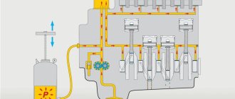
Before considering the design of the Stirling engine, it would be useful to consider the disadvantages of steam engines. It is clear that the steam formed from heating the water moves through the pipe into the cylinder through the open inlet valve, where it pushes the piston and drives the wheel connected to the piston.
The inlet valve then closes and the outlet valve opens. The momentum of the wheel causes the piston to return to the cylinder and push the cooled steam through the smoke (steam) pipe.
Steam system diagram: 1 – valve stem; 2 – side valve; 3 – high pressure steam inlet; 4 – steam output; 5 – cross head; 6 – crosshead guide; 7 – piston rod; 8 – piston; 9 - cylinder
The design of a steam engine is far from ideal. In any case, there are four obvious disadvantages.
- The boiler produces high pressure steam, so there is always a risk of explosion.
- The boiler is structurally located at some distance from the cylinder, so energy losses are obvious.
- The exhaust steam released also contributes to energy losses.
- A steam engine consumes huge amounts of water and fuel.
Stirling engine design
The shortcomings noted above, however, can be eliminated. For example, get rid of the boiler (eliminating the risk of explosion), and also use the heat of the fire to directly power the engine. Then, instead of using steam to move the thermal energy, you can use regular air (or another gas) to move the thermal energy.
If you put this gas component inside a closed pipe, and organize it to move back and forth again and again. This way you can get energy by eliminating the factor of constant water supply.
Finally, it makes sense to add a heat exchanger to the design to capture the energy of the hot gas inside the machine and then reuse it to improve overall efficiency. These are the main ways in which the Stirling engine stands out as a significant upgrade to steam design.
There are regenerative closed-cycle Stirling heat engines that generally follow the concept described above. Regenerative design refers to the use of heat exchangers to retain some of the heat that is otherwise lost in each cycle.
Helium use
At the same time, the idea arose to replace the working factor. Until now, by the slogan “working factor” in Stirling engines we meant ordinary atmospheric air. At some point, engineers and scientists asked the question, is there anything better in terms of thermodynamic properties? Yes. More or less since the 1930s, this gas has been sold commercially in industrial quantities. This is helium. The use of helium as a working substance significantly increases the efficiency of Stirling engines. However, the use of a new factor caused completely new problems. Helium does not store well even at room temperature. That is. Due to its very small particles, it tends to penetrate most materials used in steel head technology. In the 60s and 70s, helium engines were studied. Their characteristic feature, visible in the photographs... is attached to the engine of a helium cylinder, used to replenish the gas leaving the engine through almost all its elements. The problem was serious. To ensure competitiveness with other propulsion systems (i.e., mainly internal combustion engines), the average pressure of the working environment in Stirling engines was 20... 30 bar, and the temperature of the hot parts of the engines (heater) often exceeded 500 degrees Celsius (with a temperature difference of 400 degrees). The leakage problems of helium engines have not yet been solved practically and economically. To ensure competitiveness with other propulsion systems (i.e., mainly internal combustion engines), the average pressure of the working environment in Stirling engines was 20... 30 bar, and the temperature of the hot parts of the engines (heater) often exceeded 500 degrees Celsius (with a temperature difference of 400 degrees). The leakage problems of helium engines have not yet been solved practically and economically. To ensure competitiveness with other propulsion systems (i.e., mainly internal combustion engines), the average pressure of the working environment in Stirling engines was 20... 30 bar, and the temperature of the hot parts of the engines (heater) often exceeded 500 degrees Celsius (with a temperature difference of 400 degrees). The leakage problems of helium engines have not yet been solved practically and economically.
Stirling motors, their use at the end of the 20th century
At the end of the 20th century, Stirling engines made a comeback. Both NASA, the US State Department and the European Union have invested in research into new generations of Stirling engines. They were primarily designed for solar systems (i.e., the heat source would be sunlight focused onto the engine heater by a large parabolic mirror). Many of these engines had uneven designs.
Example of a Stirling engine design proposed by Mr. Maciej Zukasz according to patent P.389415. The project was carried out as part of a master's thesis at the Faculty of SiMR at the Warsaw University of Technology (supervisor: Prof. Wiaslaw Ostapski, PhD, Eng.
The idea behind this idea was that the entire motor with electric generator would be sealed in a sealed (helium) non-removable housing, with the idea that it could not be used for the entire life of its life. However, this time the technology failed. If positive results were obtained, they were associated with too high a cost. In the best way, the most common Stirling engines in the twentieth century remained in India: table fans, structurally similar to the above-mentioned aquarium pumps...
An example of a solar system with an electric generator driven by a Stirling engine. Source: Wikimedia Commons, Author: Uploaded by Skyemoor.
One of the latest ideas for using Stirling engines was “parameter descent.” That is, they are used for engines with low performance and significantly lower efficiency than internal combustion engines and electric motors. Around the beginning of the 21st century, with the help of Stirling engines, the idea of recovering energy lost in heating processes such as the flue gas "flue" from CO furnaces was discovered. However, economic calculations were still against the use of such solutions on a large scale.
Of course, despite all the technological problems, Stirling engines are produced and used. However, these are very specific applications that make it possible to justify high production and/or operating costs. In addition to military applications, examples include energy systems powered by biogas recovered from landfills.
A commercially available electric generator driven by the STM Stirling engine since the early 21st century. Electrical power: about 38 kW or 65 kW. Body height: about 1 m. Source: Wikimedia Commons, author: V.T. Chimansky.
Stirling engines - a technological breakthrough in autonomous energy of the 21st century
N.G. Kirillov, Doctor of Technical Sciences, Academician of the Academy of Military Sciences, Honored Inventor of the Russian Federation.
Stirling engineering is a new promising direction in the field of engine building
It is now obvious to everyone that one of the main directions of economic development and scientific and technological progress in the 21st century is the task of searching for promising technologies for energy conversion and mass production of new equipment based on highly efficient thermodynamic cycles using renewable fuels and new working fluids. This means the creation, production and introduction into mass use of such highly efficient and environmentally friendly energy systems that would ensure the satisfaction of the energy needs of industry and the population with minimal expenditure of material resources.
In all developed countries of the world (primarily the EU and the USA), the basis for innovative development of industry is the task of transitioning to a new technological level associated with energy saving, ecology and reducing the share of traditional energy resources. Thus, by 2025 in the EU countries more than 20% of energy will be produced through the use of alternative and renewable fuels. As part of solving these problems, according to many foreign experts, the most promising way is the development, production and widespread implementation of energy-converting systems based on Stirling engines.
The thermodynamic cycle of the engines in question was proposed in 1816 by the Scotsman Robert Stirling. The presence of two isotherms determines the equality of the thermodynamic efficiency of the ideal Stirling cycle and the Carnot cycle. Therefore, theoretically, Stirling cycle engines are potentially the most highly efficient of all existing engine types.
The first most intensive and serious work on the creation of competitive Stirling engines, characterized by clean emissions, low noise levels due to the absence of explosive combustion, the absence of gas distribution and ignition systems, and high fuel efficiency, began in 1934 in the Dutch.
From 1975 to the 1990s, work on the creation of Stirling engines was carried out mainly for automotive companies such as General Motors Co, Ford Motor Co, MAN-MBW and for military needs. Stirling transport engines, as a rule, were of the double-acting type, with a linear drive, etc. When creating Stirling transport engines, taking into account the large number of start-stop cycles and frequently changing power, stringent requirements for weight and size, expensive materials were used (for example, cobalt, zinc, copper, nickel, etc.) and complex technological execution of original structural elements. This approach made it possible to achieve the highest efficiency indicators among all piston engines, but also significantly increased the cost of the products. Currently, transport types of Stirling engines are widely used abroad in aerospace engineering, submarine shipbuilding, as energy sources for portable communication stations for sabotage groups and special forces, as well as in other areas of military technology.
Since the mid-90s of the last century, the direction of stationary power plants began to prevail in the field of creating Stirling engines. During their mass production and operation, the most significant indicator is the cost, which consists of the cost of manufacturing and maintenance. Mass and dimensional characteristics for stationary cogeneration plants are not so decisive. Based on this, modern types of Stirling engines incorporate new technical solutions that have significantly reduced their cost. It should be noted that a number of foreign companies have begun production of engines whose technical characteristics are already superior to internal combustion engines and gas turbine units in the power range from 1 to 100 kW.
The main technical characteristics of power plants based on Stirling engines offered on the market today, depending on the manufacturer, range from:
— specific cost from $1,300 to $3,000 per kilowatt of installed capacity;
— motor life from 20,000 to 87,000 hours;
— effective efficiency up to 45%.
It should be noted that in recent years, serious changes have been taking place in the market for Stirling engine manufacturers. Almost all major energy companies in the world have begun work on creating Stirling engines. The world's leading power plant companies such as TODEM, CumminsPowerGeneration, ToshibaCorp., MitsubishiElectricCorp. announced their Stirling engine programs. etc. Only in the last year, 2007, new powerful associations have appeared, for example, the European Swiss-German concern “Stirling Systems AG” and the transnational corporation, which includes leading American, Japanese, Italian and German energy firms (“Merloni Termosanitari ( MTS Group)” (Italy), “Bosch Group” (Germany), “Rinnai” (Japan), “Infinia” (USA).
The emergence of such large companies, combining significant financial and production capacities, is explained by a new higher level of requirements for the efficiency of energy systems, their environmental cleanliness, and increasing requirements for the use of renewable and clean local energy resources. Of course, in the near future this will lead to fierce competition in the market for Stirling engines and autonomous power plants in general.
The prospects for using Stirling machines in various fields of energy have now become obvious to all industrialized countries of the world, so according to foreign experts, at present, around the world, at least 140 research organizations and companies are conducting intensive research in this direction. The leading countries in the field of design and creation of Stirling machines are the USA, Great Britain, Japan, Germany, Sweden and the Netherlands. In addition to the listed countries, intensive research on Stirling engines has recently begun in China, South Africa, Australia, Israel, Canada, India and a number of other countries. Objectively, in the last 15-20 years, a new promising branch of mechanical engineering has begun to take shape in the world - Stirling engineering.
What are Stirling cycle machines?
Stirling machines are machines operating in a closed thermodynamic cycle, in which cyclic processes of compression and expansion occur at different temperature levels, and the flow of the working fluid is controlled by changing its volume.
Structurally, Stirling machines are a successful combination in one unit of a compressor, an expander and heat exchange devices: a load heat exchanger (heater or condenser), a regenerator and a refrigerator. As a rule, helium is used as a working fluid, as well as nitrogen and air.
The advantages of machines operating on the Stirling cycle include a high degree of environmental cleanliness of both the working fluids of Stirling machines themselves and the waste media generated during their operation, as well as energy efficiency.
The advantages of Stirling machines include a number of fundamental properties that are unique to these machines and create real prerequisites for their widespread use in almost all areas of industry and technology, the main of which are:
* wide versatility of the thermodynamic cycle itself, which allows, with different designs, to create both forward cycle converters (engines) and reverse cycle converters (refrigeration and cryogenic machines);
* highest energy efficiency (the theoretical efficiency of the cycle of an ideal Stirling machine is equal to the efficiency of the Carnot cycle);
* high degree of environmental cleanliness of both the working fluids of Stirling machines themselves and the waste media arising during their operation;
* multi-fuel engines - the possibility of using not only the combustion of traditional energy carriers (petroleum products, natural gas, etc.), but also solar radiation, biogas, wood, peat, coal, etc. as heat sources.
Among the manufactured engines, power plants with a Stirling engine are the most environmentally friendly, since the concentration of harmful substances in the combustion products of a Stirling engine is almost two orders of magnitude lower than that of other piston and gas turbine engines. The most important consumer property of Stirling engines is the lowest noise level compared to all existing engines of other types. Currently, this figure for the Stirling engine fluctuates at 60-65 dB. This makes it possible to install stirling generators in close proximity to the consumer, which will eliminate losses in the transmission of electricity.
Modern areas of application of power plants with Stirling engines
Modern world energy is developing in the direction of decentralization of energy supply, which promotes the creation of autonomous cogeneration plants and the maximum use of renewable energy sources. The exceptional property of Stirling engines, as an engine with an external heat supply, allows the use of not only traditional types of fuel, but also all types of alternative fuels, without exception, currently known in the world, for example, biogas, coal, waste from the woodworking industry and agriculture, solar , nuclear, high-potential heat of flue gases and any other types of energy, makes them especially attractive in connection with the use of energy from renewable sources. The Stirling engine can be used in all areas where the conversion of thermal energy into mechanical energy is required.
Cogeneration power plants with Stirling engines running on traditional gas fuels (natural gas and propane).
High environmental friendliness and efficiency ensure the prospects of using Stirling engines in cogeneration units (CHUs) with a power of up to 100 kW, for the simultaneous generation of electricity and heat in places of their direct consumption. This is a new technology for the combined production of electricity and heat, based on autonomous engines and a heat recovery system, in which the energy of cooling water and exhaust gases is used to supply heat to consumers. The efficiency of using Stirling engines in cogeneration plants, compared to internal combustion engines and gas turbines, is due to the peculiarity of its thermal balance, expressed in the difference between heat losses with exhaust gases and in cooling water. For the Stirling engine, this balance is 10% and 40%, respectively, which, taking into account the higher efficiency. the engine itself, allows you to create compact and highly efficient cogeneration units (CHU). Efficiency Modern foreign stirling generators, taking into account the additional heat received, can reach up to 95%.
In Fig. 1 shows a Stirling engine running on natural gas with a power of 9 kW. This engine is part of a cogeneration unit that generates an additional 27 kW of thermal energy.
The use of HRSGs based on Stirling engines makes it possible to reduce fuel consumption for the production of electricity and heat by 40% compared to centralized energy supply. The cost of 1 kWh of electricity generated in a cogeneration plant is 3 - 4 times lower than the current tariffs of centralized energy systems (for Russia!!!), and the heat is actually free! The use of heat and power supply systems makes it possible to effectively supplement the heat and power supply market without reconstructing old, overloaded networks. The autonomous operation of the cogeneration unit allows us to provide consumers with heat and electricity with stable temperatures and high-quality hot water.
Since 2008, Germany and a number of other developed countries have been implementing federal energy programs to install Stirling engine cogeneration units with an electrical power of 1.5 kW or more in houses and apartments. According to German experts, the implementation of this project will avoid the construction of three large nuclear power plants in the country.
Power plants with Stirling engines running on solid bioresources.
Currently, due to the depletion of previously explored reserves and the rise in price of organic fuel (oil and natural gas), for many countries of the world the possibility of mass production of medium-power electric generators (from 3 to 100 kW) with modification of the Stirling engine for local fuel is of significant interest. Peat, crushed coal, shale, agricultural waste and wood processing industry waste can be used as local fuel for stirling generators. The solution to this issue in the near future will make it possible to provide many regions of the world with cheap to operate autonomous energy sources using local fuel.
Currently, cogeneration units with Stirling engines have already appeared on the market, for which wood chips, peat, biogas and agricultural waste are used as fuel.
A return to bioresources is not a return to the past, but a reasonable approach to economics and ecology. The widespread use of autonomous energy sources running on local fuel reflects the global trend towards energy and resource conservation. This area is developing most intensively in countries with a significant reserve of biological resources (forests, peat bogs, etc.), which include: Sweden, Norway, Denmark, Finland, Russia, countries of Africa and South America. In Russia, many regions have huge reserves of local cheap fuel. For example, Karelia (northwestern region of Russia) has significant resources of constantly renewable biomass in the form of woody plants, peat and agricultural waste, which can be used for energy purposes. Peat reserves in Karelia are estimated at 2 billion tons and the resources of hardwood raw materials are about 2 million m3/year. Only through the use of peat and wood raw materials can the volume of imported fuel be reduced by 60%, and this is almost a third of the budget of the Republic of Karelia.
Figure 2 shows a 28.5 kW Stirling engine running on wood chips.
Power plants with Stirling engines running on generator gas.
Another area of use of stirling generators operating on solid biomass is the use of biomass gasification technology. Gasification of wood waste produces fuel gas, which is based on CO, H2 and N2 and which can be used as gaseous fuel for Stirling engines. When producing generator gas from wood, its calorific value is usually 12-13 MJ/kg, specific gravity - 1.10 to 1.15 kg/m3. Gas output, on average, is 1.8-2.5 cubic meters. for every kilogram of biomass gasified. Due to the high efficiency of the gasification process (producer gas yield is 85-90%), as well as the convenience of using gas as fuel, gasification is a cleaner and more efficient way to produce heat than burning solid fuel directly in the boiler furnace. Another important advantage is that low-quality fuel can be used to operate the gas generator - sawdust, shavings, crushed bark.
Processing wood waste using the method of pyrolysis gas generation makes it possible to obtain cheap energy. A gas generator can solve the problems of providing heat and electricity to the population of a small village or a remote urban outskirts of a large city. Waste from the nearest forest can be used as loading material - dismantled windbreaks, bark, wood waste from planned fellings, branches, etc. The gas generator can use the worst waste wood, low in calories and containing a high percentage of moisture - up to 50 %. The size of wood waste used as fuel can be up to 30 cm.
The operation of the gas generator is based on the principle of converting solid fuel into gaseous fuel under the influence of high temperature without access to oxygen. As a result of a process called pyrolysis, generator gas, wood gas, is produced. The gas generator installation is extremely simple in design and does not require specially trained maintenance personnel to operate. The gas generator consists of three main parts: a gas generation chamber, an ignition chamber and a loading hopper. Installation parts operating at elevated temperatures are made of heat-resistant materials. The high profitability of gas-fired stirling generators is determined by the low cost of electrical and thermal energy, the use of local fuels, proximity to consumers, the absence of the need for expensive power lines and substations, environmental safety and mobility.
Power plants with Stirling engines running on solar energy.
High efficiency and the reliability of the Stirling engine design determine the effectiveness of its use in solar power plants (Fig. 3) . Sunlight is focused by concave mirrors to warm up the engine (as a heat source). Ambient atmospheric air can be used as a cooler. The role of such an environmentally friendly source of energy in the modern world is easy to assess. Of the known practically implemented solar installations for generating electricity, the highest efficiency. They have installations with parabolic mirrors and Stirling engines.
Among the most significant projects for the use of solar energy at present is the project to create a grandiose solar farm in the southern United States. According to this project, on the territory of the state of Nevada with an area of 160 square meters. km, a solar energy system based on “solar” Stirling engines will be created, which has no analogues in the world. Ultimately, the project involves compact placement of tens of thousands of such installations that will transform solar energy and supply electricity to southwestern US distribution companies.
Rice. 4 . Solar farm with Stirling engines in Nevada
According to the calculations of American experts, if this project is successfully implemented, a solar stirling farm will be created in the southern United States, with an area of 160x160 kilometers in the southern United States, which will completely cover the entire country's electricity needs.
The work of a number of large foreign companies on the creation of solar power plants with Stirling engines for spacecraft, orbital space stations and “lunar bases” with Stirling engines with power from 3 to 200 kW is widely known. a space version of a solar installation with a 5 kW Stirling engine was developed and built. The engine had n=3000 rpm and efficiency. equal to 37.5%. A parabolic petal concentrator with a diameter of 5.8 m was used as a heat source, which created a temperature of 947 K in the receiver. A heat accumulator was provided in the radiation receiver trap, which released the heat of phase transformation at a constant temperature in the shadow sections of the flight orbit. This anaerobic plant had a mass of 250 kg and worked for a long time on one of the Geminai-type artificial Earth satellites (AES).
Currently, a number of large foreign companies are developing solar power plants with Stirling engines for various purposes, including the American corporation NASA, the English corporation, etc. Thus, United Stirling AB has created several samples of “solar Stirling” with a power of up to 25 kW.
The American company Infinia expects to complete the design of new electric generators for developing countries, built on the basis of solar Stirling engines, by the end of this year. Unlike traditional solar cells, whose efficiency ranges from 12 to 15 percent and rarely reaches 22 percent, the efficiency. Installations of Infinia based on the Stirling engine are projected by the company to be more than 24 percent. Engine power 3-5 kW.
Nuclear power plants with Stirling engine.
The main work on the creation of power plants with Stirling engines powered by nuclear energy is being carried out in the USA. The Stirling engine can ensure reliable operation of power plants with a service life of more than 5 years (up to 80,000 hours) with efficiency. conversion of thermal energy into electrical energy, equal to 35-40%. Radioisotope thermal blocks and nuclear reactors can be used as a heat source for the Stirling engine. It is planned that nuclear power plants with Stirling engines with a power of 0.5 to 15 kW should be used on long-lived manned and unmanned spacecraft. Power plants with a power of 15 to 200 kW and more expediently used on manned orbital stations or on manned lunar bases with large power requirements. Thus, according to the “SP-100” project, a nuclear power plant with three Stirling engines with a total power of 250 kW and a mass of 3000 kg is being created for the planned lunar base in the United States.
In 2011, NASA sent a research probe with a nuclear reactor on board to the moons of Jupiter. But even earlier - in 2009 - the nuclear engine is planned to be used in the next American Mars mission. Lockheed Martin and the Glenn Center are developing “atomic Stirlings” for NASA. Currently, a 25 kW Stirling engine has already been developed, which will be installed in a power plant with radioisotope pumping.
Rice. 5.
The Nuclear Power Program aims to dramatically (by 1-2 orders of magnitude) increase the scientific impact of interplanetary missions by increasing the operating time and productivity of spacecraft and instruments, placing several landing vehicles on the ISS, instruments with high energy consumption, as well as organization of high-speed communication channels.
Power plants with Stirling engines running on non-traditional gas fuel (biogas, landfill gas, associated petroleum gas, etc.).
One of the areas for using local bioresources is a project to supply energy to a small settlement using Stirling engines running on biogas. Biogas is produced in digesters on the outskirts of the village and supplied through pipelines to individual houses in which cogeneration units with Stirling engines are installed. In Fig. 6 shows a sketch of this project.
Biogas is a mixture of methane and carbon dioxide and is a product of methane fermentation of organic substances of plant and animal origin, carried out by a specific natural biocenosis of anaerobic bacteria of various physiological groups. During fermentation, microflora develops in manure, which successively destroys organic substances to acids, and the latter, under the influence of syntrophic and methane-forming bacteria, are converted into gaseous products - methane and carbon dioxide.
A promising direction is the use of biogas from municipal solid waste (MSW) as fuel in Stirling engines. To produce biogas from solid waste, crushed waste in a digester is mixed with sewage sludge from the primary and secondary settling tanks of wastewater treatment plants. In 2005, for the first time in the world, an experimental energy module with a capacity of 250 kW was created in China with 5 Stirling engines running on biogas from municipal solid waste. The tests were successful for 3 years and the Chinese authorities are currently making a decision to create such energy modules at solid waste landfills in all Chinese cities.
Rice. 7. Stirling engine 50 kW
Autonomous power plants with Stirling engines (Stirling generators) are indispensable in the oil and gas industry when developing new fields, especially in the conditions of the Far North and the shelf of the Arctic seas, where serious power supply is needed for exploration, drilling, welding and other work.
Under these conditions, it will be possible to use raw natural gas, associated petroleum gas produced together with oil, and gas condensate as fuel. Such a wide range of fuels makes Stirling generators universal energy sources. Thus, the problem of providing energy to drilling wells, rotational camps, communication centers and other autonomous systems disappears.
Currently, in the Russian Federation alone, up to 50 billion m3 of associated gas, which is released along with oil, is lost annually. It is difficult and expensive to collect, it cannot be used as motor fuel for internal combustion engines due to its constantly changing fractional composition, and to prevent the gas from polluting the atmosphere, it is simply burned. However, this gas can be an acceptable motor fuel for power plants with Stirling engines.
According to preliminary calculations, a 100 kW stripping generator running on natural or associated petroleum gas will be able to provide electricity and heat to a shift camp of gas workers, oil workers or geologists of up to 50 people. There is no need to import fuel from the mainland and do not harm the environment, since harmful emissions are minimized.
On the economic feasibility of serial production of Stirling engines in the Russian Federation
In world reviews of energy conversion technology, the Stirling engine is considered as the engine with the greatest potential for further development. The Stirling engine belongs to the class of engines with external heat supply (EHS). In this regard, compared to internal combustion engines, in Stirling engines the combustion process is carried out outside the working cylinders and proceeds more equilibrium, the working cycle is realized in a closed internal circuit at relatively low rates of pressure increase in the engine cylinders, the smooth nature of the thermo-hydraulic processes of the working fluid of the internal circuit, in the absence of a gas distribution valve mechanism.
Low noise level, low toxicity of exhaust gases, the ability to operate on various fuels, long service life, comparable dimensions and weight, good torque characteristics - all these parameters make it possible for Stirling engines to significantly outperform other types of engines in the near future. Currently, the most promising is the production of Stirling engines with power from 0.1 to 100 kW, but in the near future highly efficient Stirling engines with power up to 1000 kW will appear on the world market.
Unfortunately, in Russia, due to the general economic recession, no one is developing Stirling machines at the state level, although until 1990, research in this area of technology was carried out in 15 organizations of the military-industrial complex.
Considering that currently in Russia there is practically no serial production of competitive power plants with a capacity of 1 to 50 kW, the production of highly efficient and environmentally friendly Stirling machines is the most promising direction in the development of domestic mechanical engineering. Conducted marketing research shows that the capacity of the domestic market for energy installations of this power range is up to 60 thousand units per year. The main areas of application of power plants with Stirling engines in the Russian Federation are: cogeneration using local fuel; autonomous sources for the oil and gas complex, including cathodic protection; autonomous sources for housing and communal services of populated areas; use of waste heat from waste gases of boiler plants and vehicles; anaerobic plants, etc.
The most promising is the serial production of low-power electric generators with a modification of the Stirling engine for local biofuel: peat, agricultural waste and timber processing industry. The new technology opens up wide opportunities for supplying electricity and heat to non-gasified rural areas, towns, farms, livestock farms, poultry farms, etc. It will also help solve many problems of housing and communal services in cities.
Serial production of Stirling engines will ensure the utilization of the remaining high-tech enterprises of the domestic mechanical engineering industry, the conversion of a number of the country's defense enterprises, and the export of high-tech technologies in the field of autonomous energy. Based on more than 40 years of experience in serial production
MODERN STIRLING CONFIGURATIONS
Modern engineering distinguishes three main types of such engines:
- alpha stirling, the difference of which is two active pistons located in independent cylinders. Of all three options, this model has the highest power, having the highest heating piston temperature;
- beta stirling, based on one cylinder, one part of which is hot and the other cold;
- Gamma Stirling, which in addition to the piston also has a displacer.
The production of the Stirling power plant will depend on the choice of engine model, which will take into account all the positive and negative aspects of such a project.
ADVANTAGES AND DISADVANTAGES
Due to their design features, these engines have a number of advantages, but they are not without disadvantages.
Tabletop Stirling power station, which cannot be purchased in a store, but only from hobbyists who independently assemble such devices, include:
- large sizes, which are caused by the need for constant cooling of the working piston;
- the use of high pressure, which is required to improve engine performance and power;
- heat loss, which occurs due to the fact that the generated heat is transferred not to the working fluid itself, but through a system of heat exchangers, whose heating leads to a loss of efficiency;
- a sharp reduction in power requires the use of special principles that differ from those traditional for gasoline engines.
Along with the disadvantages, power plants operating on Stirling units have undeniable advantages:
- any type of fuel, since like any engines that use thermal energy, this engine is capable of operating at a temperature difference of any environment;
- efficiency. These devices can be an excellent replacement for steam units in cases where it is necessary to process solar energy, providing an efficiency of 30% higher;
- environmental Safety. Since the tabletop kW power station does not create an exhaust torque, it does not produce noise and does not emit harmful substances into the atmosphere. The source of power is ordinary heat, and the fuel burns out almost completely;
- structural simplicity. For its work, Stirling will not require additional parts or devices. It is capable of starting independently without using a starter;
- increased performance resource. Due to its simplicity, the engine can provide hundreds of hours of continuous operation.
Advantages
The Stirling engine has the following advantages:
- For the engine to operate, a temperature difference is necessary; what fuel causes the heating is not important;
- There is no need to use attachments and auxiliary equipment, the engine design is simple and reliable;
- The engine life, due to its design features, is 100,000 hours of operation;
- Engine operation does not create extraneous noise, since there is no detonation;
- The engine operation process is not accompanied by the emission of waste substances;
- Engine operation is accompanied by minimal vibration;
- The processes in the installation’s cylinders are environmentally friendly. Using the right heat source will keep your engine clean.
Currently there are no plans or drawings for this generator
I have no plans to either produce this engine or sell plans for making its parts. This is a strictly scientific project to demonstrate the viability of this product. Difficulties and costs in the manufacture of some components were offset by the choice of average hobby-quality workmanship. Also, there are compromises in the use of RV-2 compressor elements for this engine, which will not be present in the ideal design. If this is the case, then to improve performance it would require all the thermodynamic components being housed in-house - that is, a redesigned crankcase, pistons, connecting rods, etc. Only then will it be a product that can have a certain market potential.
More recently, a complete overhaul of the heater, regenerator and refrigerator was carried out and new components were manufactured. This variant, the SV-2 MKII, includes all the niceties needed to achieve your goals. The heater head is made from billet 316 steel using an electrical discharge process. The dome and flange are welded in place. Both internal and external fins are used to enhance heat exchange with the working fluid.
External heater fins and welding seam
Internal heater fins and weld seam
The regenerator has a 316 stainless steel body using stainless steel wrap as regenerator material. The thickness is 0.001 inches. This part is made in the form of a cylindrical container. End shields hold the foil in place.
Regenerator housing
The cooler is made from 6061 T-6 aluminum alloy, also using an electrical discharge process. The outer ring forms a bypass channel for coolant. The heater, regenerator and cooler are combined into a “stack” and sealed using O-rings. Note the 1 cubic centimeter located nearby.
Stirling engine refrigerator with water jacket
The compression zone cylinder head is made of billet aluminum. The connecting channel is made of thick-walled copper pipe.
Stirling engine compression pump
The “stack” is reinforced with 4 load-bearing bolts with a diameter of 0.313 on ring-shaped clamps. This design minimizes heat leakage deep into the engine structure.
Ring clamps on a stirling engine
New design and appearance of MK II
At that moment I realized that a major upgrade was needed in order to get a good and efficient engine. Digging through my technical reference books and books, I implemented upgrades to all thermodynamic components in the gas loop. The following were redesigned: a 316 stainless steel heating cylinder head with internal and external fins, a foil for the regenerator, a finned cooler, and a new thin-walled stainless steel displacer.
Ribbed stainless steel Stirling engine heater inside and outside
My friend and Stirling enthusiast John Archibald agreed to prepare drawings from my design sketches and use his skills as a machinist to help create some of the more complex parts. It took a few more years to get all the new components, but at the end of 2012, the MK II version of the engine was ready and assembled.
Cooler with fins for Stirling engine
Engine starting
After checking the working chamber for leaks and assembling the engine, it is necessary to check its performance. For this:
- Select a source of thermal energy. It could be a candle or any other fuel. You can use a container of hot water. To do this, the lower surface of the working chamber must be placed on a container with liquid;
- Place the products on the stand. Place a source of thermal energy at the bottom of the stand;
- Place ice cubes on the upper surface of the working chamber;
- Spin the flywheel by hand.
After spinning the flywheel, the engine should start working. The piston and displacer rod will alternately act on the crankshaft of the installation. Stable operation will be ensured by the inertia force of the flywheel.
From the above it follows that the Stirling engine is a power unit that operates on the temperature difference of the working fluid. The engine can run on any type of fuel. The power plant model can be assembled independently at home. This does not require specialized materials and equipment. A spark plug, dry fuel, etc. can be used as a power source for the power plant model.
Inspired by Philips MP1002C
In the mid-80s, I had the pleasure of witnessing testing of a Philips MP1002C generator set that actually worked. The experience made a deep impression on me, especially in how calmly the Stirling started up and came to life. The maximum noise came from the burner (combustion chamber), but ultimately the Philips engine produced a very pleasant sound background - all that needed to be replaced were the noisy bearings.
As the old saying goes, “It worked and worked like a Singer sewing machine!” At the time, my experience with Stirling engines consisted of designing a few bench-top sized models, but after seeing and hearing a Philips engine in action, I wanted to design, design and build an engine of the same caliber...make something large enough that it would produce a useful, perceptible work.
Layout of cylinders in a double range.
The figure shows two “hot” cylinders in which the displacers are located. They operate in different directions with a phase shift of 180°. To simplify the operating diagram, the regenerator is not indicated in the figure. The red lines indicate the heating areas of the cylinders (heater), and the blue lines indicate the cooling areas (refrigerator).
Below in the center is a working cylinder with a working piston. Depending on the position of the displacers, it can take the values of top dead center (TDC) or bottom dead center (BDC). In order not to overload the circuit, I deliberately omitted the drive mechanics. It can be chosen at the discretion of the developer himself.
Operating principle of a high temperature Stirling motor
The left and right parts of the cylinder do not touch each other. There is a heat insulator between them. When the displacer is on the left side, it displaces all the hot air to the right, the air cools down, drawing in the working piston. When the displacer goes to the right, it expels all the air into the hot chamber, the air heats up, expands and displaces the working piston to the right. The working piston and the displacer are connected by a crankshaft with an offset of 90 degrees. Then the cycle repeats.
DIY electronics in a Chinese store.
Diagram of a high temperature Stirlink engine
Next, all the mechanics are clearly shown in the video. In the second part of the video, one of the options for assembling Stirling.
To finally understand the principle of operation of the Stirling motor, you need to assemble its working design and, in the process of fine-tuning, improve it and test it in different configurations. For the simplest understanding of the laws by which the engine operates, it is enough to do this: - make a cylinder with a displacer; — instead of the working piston, install a rubber balloon; — do not install the flywheel yet; — heat the lower part of the device, cool the upper part and begin to change the position of the displacer; - if you try to lift the displacer upward, the ball will suddenly inflate; - if you lower the displacer down, the ball will deflate. Thus, these simple steps will clearly show how everything happens in the engine mechanism. — Next, replace the balloon with a piston; — the piston should move freely, but everything should be adjusted so that it does not allow air to pass through; — lubricate the piston with silicone grease; - do the same actions that were previously performed with the ball, but with the piston; - observe the stroke of the piston, record it in notes in a work notebook in order to calculate the stroke (bend) of the crankshaft; — make a flywheel, connecting rod, crankshaft and that’s it, the Stirling engine is ready! — final testing of the finished device.
Stirling from GM
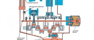
Serious work to improve the external combustion engine, which began 150 years after its invention, has already borne fruit. Various design options for an engine operating on the Stirling cycle have been proposed. There are designs of motors with an inclined washer to regulate the stroke of pistons, a rotary engine has been patented, in one of the rotor sections of which compression occurs, in the other - expansion, and heat is supplied and removed in the channels connecting the cavities. The maximum pressure in the cylinders of individual samples reaches 220 kg/cm2, and the average effective pressure reaches 22 and 27 kg/cm2 and more. Efficiency increased to 150 g/hp/hour. The greatest progress was achieved by General Motors, which in the 1970s built a V-shaped Stirling with a conventional crank mechanism. One cylinder is working, the other is compression. Only the working piston is located in the worker, and the displacer piston is located in the compression cylinder. A heater, regenerator and cooler are located between the cylinders. The phase shift angle, in other words, the angle of lag of one cylinder from the other, in this “Stirling” is 90°. The speed of one piston should be maximum at the moment when the speed of the other is zero (at top and bottom dead centers). The phase shift in the movement of the pistons is achieved by positioning the cylinders at an angle of 90°. Structurally, this is the simplest “stirling”. But it is inferior to the engine with a diamond crank mechanism in balance. To completely balance the inertial forces in a V-shaped engine, the number of its cylinders must be increased from two to eight.
Schematic diagram of a V-shaped Stirling
: 1 - working cylinder; 2 - working piston; 3 - heater; 4 - regenerator; 5 - heat-insulating coupling; 6 — cooler; 7 - compression cylinder.
The operating cycle in such an engine proceeds as follows. In the working cylinder 1 gas (hydrogen or helium) is heated, in the other, compression cylinder 7 it is cooled. When the piston moves upward in cylinder 7, the gas is compressed - the compression stroke. At this time, piston 2 in cylinder 1 begins to move down. Gas from cold cylinder 7 flows into hot cylinder 1, passing sequentially through cooler 6, regenerator 4 and heater 3 - heating stroke. Hot gas expands in cylinder 1, doing work - the expansion stroke. When piston 2 moves upward in cylinder 1, gas is pumped through regenerator 4 and cooler 6 into cylinder 7—the cooling stroke. This “stirling” scheme is most convenient for reversing. In the combined housing of the heater, regenerator and cooler (their structure will be discussed later) dampers are made for this purpose. If you move them from one extreme position to the other, the cold cylinder will become hot, and the hot cylinder will become cold, and the engine will rotate in the opposite direction. The heater is a set of heat-resistant stainless steel tubes through which the working gas passes. The tubes are heated by the flame of a burner adapted for burning various liquid fuels. The heat from the heated gas is stored in the regenerator. This unit is of great importance for obtaining high efficiency. It will serve its purpose if it transfers approximately three times more heat than the preheater, and the process takes less than 0.001 seconds. In a word, this is a fast-acting heat accumulator, and the heat transfer rate between the regenerator and the gas is 30,000 degrees per second. The regenerator, whose efficiency is 0.98 units, consists of a cylindrical body in which several washers made of wire tangle (wire diameter 0.2 mm) are arranged in series. To prevent heat from being transferred to the refrigerator, a heat-insulating coupling is installed between these units. And finally, the cooler. It is made in the form of a water jacket on the pipeline. Stirling power is regulated by changing the working gas pressure. For this purpose, the engine is equipped with a gas cylinder and a special compressor.
Child of the era of steam
The beginning of the 19th century was the heyday of the era of steam. Thanks to steam engines, industry and transport began to develop rapidly. They turned out to be extremely reliable, resistant to load fluctuations, durable, low maintenance, easy to maintain and practically “omnivorous” in relation to fuel.
Robert Stirling and his engine
There were also obvious disadvantages - low efficiency (no more than 10%) and the presence of a bulky crank mechanism (CCM). Often steam boilers exploded, unable to withstand excessive steam pressure, which led to destruction and casualties.
Steam locomotive based on Stirling engine
That all changed on September 27, 1816, when Scottish clergyman Robert Stirling patented a unique invention called the “hot air engine,” a safe alternative to its steam-powered predecessor. Later it was named after its creator - the Stirling engine (DS).
Renaissance
These engines began to develop again thanks to Philips. In the mid-twentieth century, General Motors entered into an agreement with it. She led developments for the use of Stirlings in space and underwater devices, on ships and cars. Following them, another company from Sweden, United Stirling, began to develop them, including possible use on passenger cars.
Today, the linear Stirling engine is used in installations of underwater, space and solar vehicles. There is great interest in it due to the relevance of issues of environmental degradation, as well as the fight against noise. In Canada and the USA, Germany and France, as well as Japan, active searches are underway to develop and improve its use.
Examples of implementation of external combustion engines in cars
Operable models of such an engine were released, despite all the manufacturing difficulties. In the 50s of the 20th century, automobile companies became interested in this type of power unit. The sales of Stirling engines in cars were mainly carried out by Ford Motor Company and Volkswagen Group. The Swedish company UNITED STIRLING developed such an engine in which the developers tried to use serial units and components (crankshaft, connecting rods) more often. A four-cylinder V-engine was developed with a specific mass of 2.4 kg/kW. A compact diesel has a similar weight. They tried to install the engine on seven-ton cargo vans.
The most notable success was the Philips 4-125DA, available for installation in passenger cars. The engine's operating power was 173 horsepower. The dimensions were not much different from a conventional gasoline internal combustion engine.
General Motors has developed an eight-cylinder V-shaped external combustion engine with a serial crank mechanism. In 1972, a limited version of Ford Torino cars was equipped with such an engine. Moreover, fuel consumption has decreased by as much as 25% compared to previous models. Today, several foreign companies are trying to improve the design of this engine in order to adapt it for mass production and installation in passenger cars.
The price of being methodical
When you learn about an old technical idea that has been revived in modern technology, the question immediately arises: what prevented its implementation before? What was that problem, that “clue”, without solving which she could not make her way into life? And it almost always turns out that an old idea owes its revival either to a new technological method, or to a new design that predecessors had not thought of, or to a new material. The external combustion engine can be considered a rare exception. Theoretical calculations show that the efficiency "Stirling" and "Erickson" can reach 70 percent - more than any other engine. This means that the failures of their predecessors were explained by secondary, in principle removable factors. The correct choice of parameters and areas of application, a scrupulous study of the operation of each unit, careful processing and fine-tuning of each part made it possible to realize the benefits of the cycle. Already the first experimental samples gave an efficiency of 39 percent! (The efficiency of gasoline engines and diesel engines, which have been developed for years, is 28-30 and 32-35 percent, respectively.) What possibilities did both Stirling and Erickson “look through” in their time? the same container in which heat is alternately stored and released. Calculating a regenerator in those days was simply impossible: the science of heat transfer did not exist. Its dimensions were taken by eye, and as calculations show, the efficiency of external combustion engines very much depends on the quality of the regenerator. True, its poor performance can be compensated to a certain extent by increasing pressure. The second reason for the failure was that the first installations operated in air at atmospheric pressure: their sizes were huge, but their power was small. Having brought the efficiency regenerator to 98 percent and filling a closed loop with hydrogen or helium compressed to 100 atmospheres, modern engineers have increased the efficiency and power of Stirlings, which even in this form have shown efficiency. higher than that of internal combustion engines. This alone would be enough to talk about installing external combustion engines in cars. But high efficiency alone does not exhaust the advantages of these machines, revived from oblivion.
The first type of engine. "Alpha"
The first model to be used was Stirling's Alpha. The peculiarity of its design is that it has two power pistons located in separate cylinders. One of them had a fairly high temperature and was hot, the other, on the contrary, was cold. Inside the high-temperature heat exchanger there was a hot cylinder-piston pair. The cold steam was inside a heat exchanger at a low temperature.
The main advantages of external combustion heat engines were that they had high power and volume. However, the temperature of the hot steam was too high. Because of this, some technical difficulties arose in the process of manufacturing such inventions. The regenerator of this device is located between the hot and cold connecting tubes.
Second sample. "Beta"
The second sample was Stirling's Beta model. The main design difference was that there was only one cylinder. One of its ends acted as a hot pair, while the other end remained cold. A piston moved inside this cylinder, from which power could be removed. There was also a displacer inside, which was responsible for changing the volume of the hot working area. This equipment used gas that was pumped from a cold zone to a hot zone through a regenerator. This type of external combustion engine had a regenerator in the form of an external heat exchanger or was combined with a displacer piston.
conclusions
If the shortcomings of the external combustion engine are eliminated, then this type of power unit will replace the internal combustion engine and even electric motors. But due to the high cost of materials, the complexity of their processing and the cumbersome design, the external combustion engine cannot yet be mass produced. Perhaps someday a cheap heat-resistant and pressure-resistant material will be developed that will be used in the manufacture of the Stirling engine, but for now the entire structure costs manufacturers much more than a conventional internal combustion engine. Good luck and easy travels!