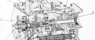
The basis of a piston internal combustion engine is a cylinder block, inside and outside of which parts of its mechanisms and systems are located.
The cylinder block is closed on top by a head, and on the bottom by a pan.
The timing gear housing is reinforced in the front part, and the flywheel housing is reinforced in the rear part.
Promotional offers based on your interests:
The engine mechanisms and systems, as well as their main indicators, include the following.
The crank mechanism serves to convert the reciprocating motion of the piston (pistons) into rotation of the crankshaft. In addition, it is involved in the conversion of thermal energy into mechanical energy.
The action of the mechanism is that the piston, performing a reciprocating movement through the connecting rod, rotates the crankshaft 1 in the bearings.
During reciprocating motion, the pistons occupy different positions, at which the volume of the cylinder changes.
Top dead center (TDC) is the position of the piston in the cylinder at which the distance from the bottom of the piston to the axis of the crankshaft is greatest.
Bottom dead center (BDC) is the position of the piston in the cylinder at which the distance from the bottom of the piston to the axis of the crankshaft is the smallest.
The stroke of the piston S is equal to its movement between dead points.
The working volume of the cylinder Vh is equal to the volume released by the piston when moving from c. m.t.k.n. m.t.
Compression chamber volume Vc is the volume formed above the piston when it is in. m.t.
Rice. 1. Main parts of an internal combustion engine: 1 - crank mechanism; 2 — gas distribution mechanism; 3— power supply system; 4 — cooling system; 5 — crankcase ventilation; 6 — balancing mechanism; 7 - lubrication system; 8 — starting system; 9 - pallet; 10 — cylinder block; 11 — cylinder head.
The gas distribution mechanism (see Fig. 3) is designed to communicate the combustion chamber of the cylinder (at strictly established moments) with the intake and exhaust channels of the engine.
A balancing mechanism is installed on some engines to eliminate the harmful effects of inertial forces that arise during operation of the crank mechanism.
Power supply and control systems serve to clean air and fuel from mechanical impurities and water and supply them to the combustion chamber, as well as to ensure uniform rotation of the engine crankshaft during operation with variable loads.
The lubrication system ensures cleaning and supply of clean oil to the working surfaces of engine parts to reduce friction and remove excess heat from them.
The cooling system removes excess heat from engine parts and maintains the required thermal conditions during engine operation.
The starting system is used to rotate the crankshaft when starting the engine.
The ignition system is used in gasoline engines to ignite the working mixture. Tractor engines running on diesel fuel do not have such a system, and the fuel self-ignites due to the high temperature generated in the combustion chamber during the compression stroke.
Engine crankcase ventilation. During engine operation, through leaks between the piston rings and cylinders, combustion products, air, fuel vapor and water enter the crankcase from the combustion chambers. These substances, entering the crankcase and moving with the atomized oil, cause its accelerated aging, corrosion of engine parts, create increased pressure in the chamber and oil leakage through various engine seals.
Rice. 2. Engine diagram: a - piston at top dead center; b - piston at bottom dead center; 1 - crankshaft; 2 - piston; 3 — connecting rod; 4 - cylinder.
In order to avoid excessive pressure build-up, a device called a breather is installed on the engine, through which the crankcase communicates with the atmosphere surrounding the engine; All escaped gases from the combustion chamber exit through it. If in the engine crankcase, after stopping its operation, the pressure of the cooled air in it is below atmospheric pressure, then air from the atmosphere will enter the crankcase through the breather and eliminate the vacuum.
Breathers are made differently for different engines: for some, for example, the breather is tube A, at the base of which there is a filter pack made of steel wire, designed to protect the crankcase from dust, sand and prevent the release of oil from the crankcase into the atmosphere. On other engines, breather B is connected to the filler cap for filling with oil.
Domestic tractors are equipped with piston internal combustion engines. The principle of their operation is based on the property of heated gases to expand.
Below is the purpose of engine mechanisms and systems.
The crank mechanism perceives the pressure force of gases heated during the combustion of the air-fuel mixture and converts the reciprocating motion of the piston into rotational motion of the crankshaft. This engine mechanism consists of a cylinder with a head, a piston with piston pin rings, a connecting rod, a crankshaft, and a crankcase flywheel (with a pan).
The distribution mechanism promptly admits the air-fuel mixture (for carburetor engines) or air (for diesel engines) into the cylinder and releases exhaust gases from the cylinder. The mechanism consists of a camshaft, gears, valves and their springs, rocker arms, rods and pushers.
The power supply and control system provides the engine with the required amount of air-fuel mixture of a certain composition.
The cooling system maintains the normal thermal regime of a running engine.
The lubrication system supplies oil to the rubbing parts of the engine, which reduces friction and wear.
For carburetor engines, the ignition system ensures ignition of the working mixture in the cylinder.
The starting system ensures the engine starts.
If you move the piston in the cylinder, the crankshaft will begin to rotate, and vice versa, if you rotate the crankshaft, the piston will move up and down, i.e. reciprocating.
The extreme positions of the piston are called dead centers: at the top dead center (TDC) the piston is farthest away from the axis of the crankshaft, and at the bottom (BDC) it is as close as possible to the axis of the crankshaft. At dead points, the piston speed is zero.
Crawler tractor design
The location of the main parts and assembly units of a caterpillar tractor is shown in the figure.
Drawing. Layout of the main parts, mechanisms and parts of a caterpillar tractor: 1 - engine; 2 — hydraulic mounted system; 3 — tow hitch; 4 - drive wheel; 5 — planetary mechanism; 6 — final drive; 7 — gearbox; 8 - connecting shaft; 9 — clutch; 10 — caterpillar chain; 11 — guide wheel; 12 - main gear.
Engine 1 converts the chemical energy of fuel and atmospheric air into rotational motion and transfers it to consumers - the drive wheels and PTO.
The transmission transforms the rotational motion, distributes it and transfers it to the drive wheels (track sprockets). The transmission consists of a clutch 9, a connecting shaft 8, a gearbox 7, turning mechanisms 5, a main gear 12 and final gears 6.
The chassis combines all assembly units into one and serves to move the tractor along the supporting surface. The chassis consists of a frame (frame), suspension and propulsion unit, which includes drive wheels 4 (sprockets), guide wheels 11, support rollers and track chains 10. The propulsion unit interacts with the supporting surface (soil) and converts the rotational motion supplied by the transmission into forward movement of the tractor.
Control mechanisms, acting on the chassis, change the trajectory of the tractor, stop and hold it motionless.
The working equipment of the tractor consists of a hydraulically driven hitch mechanism 2, a tow hitch 3, a PTO and a drive pulley. The mounted system is designed to attach mounted machines to a tractor and control their operation. Various trailed machines and vehicles are towed using a tow hitch. The PTO is used to drive the working parts of aggregated machines.
The auxiliary equipment of the tractor is a cab with a sprung seat, a hood, lighting and alarm devices, heating and ventilation systems, a compressor, etc.
Operating principle of a tractor engine
An engine is a machine that converts any type of energy into energy spent on mechanical work.
In a tractor engine, this work is performed due to the thermal energy released in its cylinders during fuel combustion. Such engines are called internal combustion engines. They are divided according to the method of formation and ignition of the working mixture (diesel and carburetor), the number of strokes of the working cycle (four-stroke and two-stroke), and the number of cylinders (single-cylinder, two-cylinder and multi-cylinder).
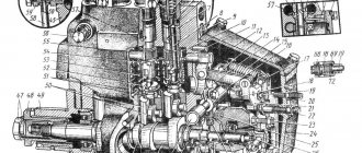
Engine diagram : 1 - crankshaft; 2 — flywheel: 3 — engine frame; 4—cylinder; 5— connecting rod; 6—piston; 7—piston pin; 8 — cylinder head; 9 — valves; 10 — transmission parts; 11—cam shaft; 12 - timing gears
To understand the operating principle of a tractor engine, consider its simplified diagram (Fig.). A piston 6 is tightly inserted into the cylinder 4, closed by the head 8, which can move in it. Using pin 7 and connecting rod 5, the piston is connected to crankshaft 1, which has a heavy wheel at one end - flywheel 2. The listed parts 1, 2, 4-8 form a crank mechanism.
As the piston moves in the cylinder, the crankshaft rotates. The extreme positions of the piston, when it seems to stop and begins to move in the opposite direction, are called the dead points of the mechanism. There are two such points: upper (a.m.t.) and lower (n.m.t.).
The path from one dead center to another is called the stroke of the piston. For each stroke, the crankshaft rotates half a revolution.
The space above the piston at TDC is called the volume of the combustion chamber, and the space located above the piston when it is at TDC. - the total volume of the cylinder.
The volume of the cylinder released by the piston when it moves from T.M.T. BC is called the cylinder displacement. The working volume of all cylinders, expressed in liters, is called engine displacement.
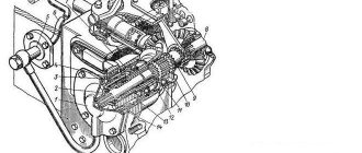
The cylinder head has inlet and outlet ports closed by valves. At precisely defined moments, they open and close using a distribution mechanism, which, in addition to the valves, includes a cam shaft 11, transmission parts 10 and timing gears 12.
Let's turn the crankshaft so that the piston comes to the top line. If you continue to rotate the shaft, the piston connected to the connecting rod will begin to move down, creating a vacuum in the cylinder above itself. At this time, the intake valve will open and ambient air will begin to flow into the cylinder. When the piston reaches the bottom position, both valves will be closed. Further rotation of the shaft will cause the piston to go up and compress the air filling the cylinder.
When the piston is at i.d.t. all the air that previously occupied the full volume of the cylinder will be compressed in the combustion chamber.
The number showing how many times the volume (compressed) of air (or a mixture of fuel and air) in an engine cylinder decreases is called the compression ratio e.
Highly compressed air is heated to high temperatures. Finely atomized fuel is injected into this air. It ignites when it comes into contact with hot air. When fuel burns, gases are formed. From high temperature they tend to expand. Therefore, the pressure in the cylinder increases sharply. Under the influence of this pressure, the piston moves downward, performing mechanical work.
The movement of the piston is transmitted to the flywheel through the connecting rod and crankshaft. At the end of the downward stroke of the piston, the exhaust valve opens. The heavy flywheel, having received acceleration, brings the mechanism out of the ground level. The piston, under the action of the connecting rod, rises and pushes exhaust gases out of the cylinder, freeing it for the next portion of fresh air. When the crankshaft rotates, all processes in the cylinder are repeated, which ensures continuous operation of the engine.
Consequently, the operation of the engine is based on the property of gases to expand when heated. It consists of four piston strokes. Each stroke corresponds to one of the following four processes: intake of fresh air, compression of it, expansion of gases as a result of fuel combustion, release of exhaust gases. Each of these piston strokes, during which certain processes occur, is called a stroke.
It is easy to see that out of four cycles, one - the expansion of gases - does useful work. This stroke is called the power stroke. The remaining three measures are auxiliary. They are accomplished due to the energy of the working stroke.
The set of cycles alternating in a certain order is called the operating cycle of the engine.
Depending on the number of piston strokes that make up the working cycle, engines are four-stroke and two-stroke.
In the engine, the operating diagram of which we have examined, fuel is injected into the cylinder and ignites from the high temperature of highly compressed air. This type of engine is called a diesel engine.
An engine in which a combustible mixture (fuel with air) is formed not in a cylinder, but in a special device - a carburetor, and then enters the cylinder, where it turns into a working mixture and is ignited by an electric spark, is called a carburetor engine.
Wheel tractor design
The purpose of the components of a wheeled tractor is the same as that of a caterpillar tractor.
Drawing. Layout of the main parts, mechanisms and parts of a wheeled tractor: 1 - steered wheel; 2 — front axle; 3 - engine; 4 — linkage mechanism; 5 - drive wheel; 6 — final drive; 7 — differential; 8 — main gear; 9 — gearbox; 10 - clutch.
The chassis and control mechanisms of a wheeled tractor consist of a frame, 2 front axle, 5 driving and 1 steered wheels, and steering. Between the main 8th and final 6th gears a differential 7 is installed.
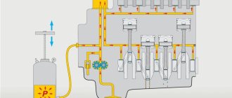
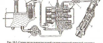
Design of a tractor diesel engine cooling system
The cooling system includes special pipelines that remove the heat generated during operation of the internal combustion engine. Due to the functioning of the entire system, the optimal temperature necessary for stable operation of the entire power unit is maintained.
To effectively cool the MTZ tractor engine, a special forced-type cooling system is constantly running. In a tractor engine, thanks to the operation of the pump, the liquid circulates in a closed cycle. Antifreeze or antifreeze is used as a coolant.
The cooling system includes the following main elements:
- Centrifugal pump to ensure constant circulation of antifreeze.
- Plate type cooling radiator. It consists of horizontal plates, brass tubes, filler and drain tanks.
- Fan for radiator cooling.
- Thermostat to control the temperature of the coolant in the system.
- Radiator curtain. This part serves to regulate the intensity of the fan air flows.
Oil change interval
Severe operating conditions ultimately lead to deterioration of lubricants due to the complex operating mechanisms of the engine. Replacement intervals typically range from 3,000 miles for short trips and severe driving conditions. But each manufacturer presents its own unique design and operation of the tractor engine lubrication system, so it is necessary to follow individual oil change instructions. Much also depends on the recommendations of specific vehicle manufacturers and information from vehicle manuals.
Main components of the lubrication system
The oil pan is a bowl-shaped reservoir. It collects engine oil, allowing fluid to circulate throughout the engine. The oil pan is located under the crankcase and stores engine oil when the engine is not running.
Poor road conditions can damage the oil pan. Therefore, manufacturers provide protection against stones and other elements that could damage this part of the tractor. The sump guard absorbs impacts on rough roads and protects against damage.
An oil pump is a device that helps circulate lubricating oil to all the moving parts inside the engine. These parts include the crankshaft and camshaft bearings, and valve lifters. It is usually located at the bottom of the crankcase, next to the oil sump. The pump supplies oil to the oil filter, which cleans and sends it onward. The oil then reaches the various moving parts of the engine through special channels.
Even small particles can clog the oil pump and passages. If the device becomes blocked, it can cause serious damage or even cause the engine to seize completely. To avoid this, the oil pump consists of a strainer and a bypass valve. Therefore, it is necessary to regularly change the engine oil and filter in accordance with the manufacturer's recommendations.
To improve engine performance and extend engine life, it is important that engine oil quickly reaches the engine's moving parts. To do this, manufacturers install oil channels in the engine. It is nothing more than a series of interconnected channels through which oil is supplied to distant components of the engine. They consist of large and small channels drilled inside the cylinder block. The larger passages connect to the smaller ones and supply engine oil to the cylinder head and overhead camshafts. Oil passages also supply oil to the crankshaft, crankshaft bearings, and camshaft bearings through holes drilled into them.
An oil cooler is a device that cools the engine oil when it gets too hot. The oil cooler transfers heat from the engine oil to the engine coolant through its fins. In addition, the element controls viscosity and also maintains the quality of the lubricant, prevents engine overheating and protects against wear.
Piston rings provide a sliding seal to prevent air or fuel leakage. Hydrodynamic lubrication works in the center of the cylinder wall and piston rings of a car when they are in good condition. The oil control ring maintains a minimum lubricant coating thickness. The part is located after the piston rings, which allows you to eliminate excess oil directly into the sump. The oil film remaining on the cylinder wall will be available to lubricate the next ring. Oil decomposition occurs due to leakage of the air mixture or fuel from the combustion chamber into the oil pan. Most often, this becomes the main reason why there is a need to constantly add oil to the engine when the level drops for unobvious reasons.
The need to use lubricant in the engine
Tractor engine lubrication system:
- Minimizes power loss by reducing friction between moving parts.
- Reduces wear on moving components.
- Provides a cooling effect to hot engine parts.
- Provides shock absorption from engine vibration.
- Performs internal cleaning.
- Helps protect piston rings from high pressure gases in the cylinder.
Without performing these procedures, any engine, regardless of design features, will be doomed to rapid wear.