Chassis of grain combines SKD-5, SK-5 AND SK-6
Purpose and content of the work .
To consolidate the knowledge on the general structure of the axle of driving and steered wheels acquired in theoretical classes. Find installation locations for chassis units on combine harvesters. Consider the differences in the designs of the chassis components of various combines. Master the disassembly, assembly and adjustment of the following units: gearbox take-up pulley assembled with the clutch; gearboxes; differential, final drive, drive and driven wheels.
Workplace equipment . Training combines with complete axles of driving and steering wheels assembled with a control platform; double-sided wrenches: 12X14; 17X19; 22X24; 22X30; 36X41; 46X50; interchangeable heads 17, 19, 22, 24, 27 mm. Wrench for round nuts 45-52 mm; tire pressure gauge, dipstick (set No. 5), dial indicator ICH05 class. 1; three-jaw puller for the gearbox receiving pulley; jack; mount; ruler 300 mm long; sliding rack 1220-1000 mm long for measuring wheel toe-in; mechanic's hammer 800 g; screwdriver A250X1.0; combination pliers 200 mm; pliers for removing retaining rings; two stands for the combine.
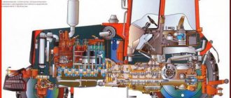
Sequence of work execution . Consider the diagram of the transmission of motion from the right end of the engine crankshaft to the drive wheels of combine harvesters. For all modifications of combines, the drive wheels are driven in the same way.
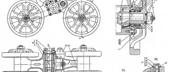
From the variator, the running gear is transmitted by a V-belt to the receiving pulley 11 (see Fig. 106), on which the clutch housing 12 is fixed. From the transmission shaft of the gearbox 13, the movement is transmitted to gear 3 of the main gear and from it through gear 2 to the left 17 and right axle shafts to the gears 19 of the final drives. The carrier 20 transmits rotation through an axle with a flange to the drive wheels 23 of the combine.
Pay attention to how the engine drive pulleys are mounted on various combines.
Note the different fastening of the flanges of the chassis variator fork on SKD-5 and other combines. Moving the mounting flange on the SKD-5 combine allows the use of highly elongated but intact chassis variator belts for work.
On SK-5 and SK-6 combines, it is more convenient to adjust the limits of movement of the variator unit using two limit bolts.
Please note that on the SK-5 and SK-6 combines, the clutch clutch, as well as the wheel brakes, is controlled using hydraulic systems.
The gearboxes on all combines have three forward gears and one reverse gear. Please note that the tachometer speedometer drive on SK-5, SK-6 and SKD-5 combines manufactured in 1973 is mounted in the cover of the external brake, interlocked with the clutch mechanism.
Consider the more durable final drives of the SK-5 and SK-6 combines and compare them with the final drives of the SKD-5 combine produced before 1973, which do not have wheel brakes.
Check the air pressure in your tires using a tire pressure gauge.
On SK-5 and SK-6 combines, when working on hard ground and on transport, the pressure in the drive wheel should be 2.8 kgf/cm2 (280 kPa), and on wet soil - 1.5 kgf/cm2 (150 kPa), respectively , in the tire of the driven rear wheel the pressure should be 2.5 kgf/cm2 (250 kPa) and 1.5 kgf/cm2 (150 kPa).
The SKD-5 combine produced before 1973 had the same pressure in the tires of the drive and steered wheels - 2.5±0.2 kgf/cm2 (245±±19.7 N/m2).
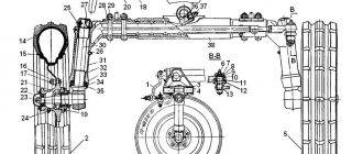
Consider the steering axle, which includes the rear beam, steering linkage, steering mechanism, power steering and steering wheels.
Please note that the SK-6 combine has hydraulic volumetric steering, and the connection between the steering wheel and the steered wheels is purely hydraulic. Find on this combine a planetary pump connected to the steering wheel shaft, a distributor and a hydraulic cylinder for the steering wheels.
Note that the SKD-5 combine has a hydromechanical control system, in which the steering mechanism is connected to the spool of the steered wheels through a longitudinal link. A number of SK-5 combines had the same steering system as the SKD-5 combine.
Prepare your workplace. Check the completeness of the tool and begin work.
Hydraulic system of the working bodies of the GS-12 combine harvester. KZS-1218 Palesse
When operating Polesie GS-12 combine harvesters, operators often have questions about the operation of the combine's hydraulic systems.
We are often contacted with questions about the purpose, location of components, operating principles and troubleshooting of hydraulic systems. Having slightly systematized the frequently asked questions, we decided to create a small guide for those who want to study these systems on their own.
In this manual, we tried to briefly, in simple language, outline the structure and operating principle of the hydraulic system of the working parts of a combine harvester.
Dismantling, assembling and adjusting drive axle units
Remove, disassemble and reassemble the front and rear wheels of the combine:
- Place the jack head opposite the mark on the drive wheel axle housing and hang the wheel. Place an additional stand under the transverse beam of the drive axle.
- Unscrew the wheel nuts and remove it from the axle flange using a pry bar.
- Place the wheel with the valve facing up, unscrew the spool and bleed air from the chamber. Push the valve into the tire.
- On the SKD-5 combine, dismount the wheel rims and remove the tire with rim tape. On other combines, remove the tire from the non-separable wheel rim.
- Remove the tube from the tire, check for foreign objects inside the tire or pieces of the metal frame of the tire. Remove metal objects or replace a tire with a damaged frame.
- Powder the inside of the tire with talcum powder, insert a tested, slightly inflated tube into the tire, and lay down the rim tape.
- Place the tire on the outer rim of the front wheel so that the tops of the corners of the tread pattern are directed in the direction of rotation. Putting the tire in reverse causes it to stick. The hole in the disk for the chamber valve should be located at the top and outside. The chamber valve must fit into the disk hole without distortion.
- Place the tire and disk on the wheel rim (SKD-5 combine), aligning the holes of the disks. Insert twelve bolts into the holes, put spring washers on them and tighten the nuts. Gaps between discs of more than 0.3 mm are not allowed.
- Inflate the tire to the recommended pressure depending on operating conditions.
Replace the tires of the rear wheels of the combine:
- Raise the right rear wheel of the combine with a jack and install a stand under the steering wheel axle. Carry out operations according to points 2-6.
- Place the tire bead onto the outer rim of the rear wheel, inserting the valve into the hole in the rim.
- Place the inner rim of the wheel on the opposite side of the tire, taking care not to pinch the rim tape. Align the holes in the rims, insert the bolts into them, place spring washers on the bolts and tighten the nuts.
- Install and secure the wheel to the hub. Remove the stand and jack.
The SK-5 and SK-6 combines have non-separable front and rear wheel disks without rim strips. Therefore, installation of tires on them must be carried out by two people and in the following order:
- Place the tire bead on the wheel rim from the side of the valve hole in it. Tires measuring 530-610 mm are placed on rims so that the tops of the tread “herringbones” are directed forward. When installing tires 310-406 mm, no distinction is made between the right and left wheels, because they have a universal tread.
- Insert the tested tube into the tire. Insert the valve into the hole in the disk and pump up the chamber.
- Place the second bead of the tire onto the rim on the side opposite the valve hole.
- Inflate the front wheel tire to an air pressure of 3 kgf/cm2 (300 kPa), and then reduce the pressure to 2.3±0.2 kgf/cm2 (230±20 kPa).
- Install the wheels on the combine.
On SK-5, SK-6 and SKD-5 combines (manufactured since 1973), the front wheels must be removed to adjust the wheel brakes and clutch. Therefore, when replacing tubes or wheels, you should simultaneously check the adjustment of the above components, and only then install the wheels.
Remove the gearbox . On SK-5 and SK-6 combines, unscrew the two nuts securing the running belt protective shield to gain free access to the chassis variator.
- Remove the hydraulic cylinder rod of the chassis variator from the mounting axis. On SKD-5 combines, loosen the clamps limiting the stroke of the pulley block fork; on SK-5 combines, unscrew the limiting bolts / and 3 (Fig. 112) from the brackets.
- Bend back the lock washer, loosen nut 11 of the coupling bolt 10 of the variator hub. Using screw 13 of the tensioning mechanism, move the pulley block to the extreme forward position and remove belt 9 from the take-up pulley.
- Undo the cotter pins and disconnect the rods from the clutch levers, gearbox rods, hydraulic cylinder and parking brake.
- Place a jack or other support under the gearbox and unscrew the nuts securing the gearbox to the differential housing. Carefully lowering the jack, disconnect the box from the drive wheel axle. Place the box with the mating surface down on the rack for disassembly.
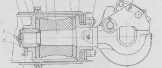
Disassemble the parking brake:
- Unlock and unscrew bolt 3 of the thrust bearing (Fig. 113). Undo the cotter pin, remove the axle washer and disconnect the fork 2 from the brake band 4. Remove the band from the pulley.
- Unscrew nut 5 and remove brake pulley 1 from the gearbox transmission shaft.
Assemble the parking brake in the reverse order of disassembly.
In the “on” position of the parking brake handle, the band 4 should tightly cover the brake pulley 1. The gap of 1 mm between the band and the pulley should be the same throughout the entire circumference, which is achieved by screwing or unscrewing the fork 2. The working stroke of the parking brake handle should not exceed 2/ 3 full turns. If the handle extends more than four teeth before braking begins, then it is necessary to shorten cable 37 (see Fig. 106).
Remove the clutch assembly with the take-up pulley:
- Unscrew the three bolts 7 (Fig. 114) and remove the cover 6. Unscrew the round nut 5 from the receiving shaft and remove the lock washer 4.
- Install the puller so that the conical part of the screw is located in the center hole of the shaft, and the three legs cover the rim of the outer pulley 10.
- By rotating the puller screw, remove the take-up pulley along with the clutch. Using a caliper, measure the distance from the end of the casing neck 23 to the pull-out levers 16. It should be equal to 24±0.3 - 33.5±0.3 mm. This size must be checked when replacing the clutch driven disc. The check must be carried out with the pull-out levers 16 installed in the same plane.
- Set nuts 21 to the required size and tighten nut 21 at three points, connecting it to fork screw 19.
- Install the clutch together with the take-up pulley onto the gearbox in the reverse order. Remember that dismantling and adjusting the clutch can be done on the combine without removing the gearbox.
Remove the final drive:
- Place a jack under the wheel axle housing on the left side and lift the combine.
- Place the bridge on the stand and lower the combine onto it. Unscrew the nuts securing the left drive wheel and remove this wheel.
- Unscrew the nuts of the final drive bolts, remove the washers and remove the bolts. Carefully remove the right and left KamTEK . Remove the axle shafts from the axle housing.
Assemble the gearbox in the reverse order of disassembly.
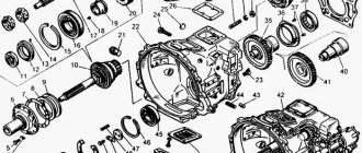
Disassemble the differential:
- Unscrew nuts 7 (Fig. 115) of the differential bearing mounting bolts, remove plates 6 and clamps 5. Remove differential 3 assembly from the axle casing.
- Undo the cotter pins and unscrew the castle nuts 10 (Fig. 116) of the bolts 4 connecting the driven gear 5 of the main gear with the cups 3. Press out the bolts, separate the cups and remove the cross 6 with satellites 7 and support washers 8. Remove the gears 1 of the axle shaft with washers 2.
Assemble the differential:
- Install cup 3 (see Fig. 116) on bolts 4. Place washer 2 and gear 1 of the right axle shaft in the cup.
- Place gears 7 with washers 8 on crosspiece 6 and place the assembled crosspiece in cup 3, engaging gear 7 with gear 1.
- Install driven gear 5 of the main gear onto cup 3 so that the bolts align with the holes in the gear. Press gear 5 into the cup recess until it stops.
- Place washer 12 and gear 13 of the left axle shaft in the second cup. Install the second cup AND onto the cross assembly, engaging all the gears.
- Align the holes for the bolts and press the second cup onto gear 5 until it stops. Screw nuts 10 onto bolts 4 and tighten them crosswise until tight. Insert cotter pins 9 into the slots of the nuts and bolt holes and lock the bolt heads.
- Heat the ball bearings in oil to a temperature of 80-90°C and press them onto the cups until they stop.
- Install the assembled differential into the axle housing.
Check the free rotation of the axle shafts and satellites by inserting the right axle shaft into them and turning them by hand. Through the windows in the cups, use a feeler gauge to check the gaps between the ends of the axle gears and the washers. They should be 0.5-1.2 mm, otherwise the installation of thickened washers of repair sizes will be required. The bolt nuts must be tightened with a torque of 10 kgf-m (980.7 N-m). All rubbing surfaces of parts must be lubricated with oil during assembly.
The differential assembled and installed in the drive axle housings must rotate freely in the bearings. Axial and radial play are not allowed.
Adjust the final drive bearings : before installing the final drives on the axle housing of the drive wheels, check the axial clearance in the tapered roller bearings 4 with a dial indicator (Fig. 117). If the indicator does not show axial play and the axle rotates freely, then the bearings need to be adjusted.
- Tighten nut 1 as far as possible, turning axis 2 to more evenly place the rollers along the cage.
- Unscrew nut 1 by */1 turn and hold it in this position with locknut 3.
- Check the axial play of axle 2 with an indicator, which should be no more than 0.2 mm.
In the same sequence, check and adjust the bearings of the second, left, final drive.
Install final drives:
- Place the gaskets onto the mating surfaces of the final drive housings. Install the gearbox with the gears facing up. Insert the right axle shaft into the gearbox, engaging the axle shaft gear with the satellite gears.
- Lift the final drive and, holding it by the axle shaft, place it in the axle housing. Carefully moving the gearbox inside the casing, simultaneously engage the splined end of the axle shaft with the differential gear and the satellite gears with the fixed gear of the axle casing.
- Push the gearbox until the flanges touch. Insert the bolts with the heads from the differential side into the aligned holes. Place the washers and tighten the nuts crosswise.
- Place the left axle shaft into the differential gear splines, slightly moving the axle shaft outward. Engage the axle gear with the satellites, and the satellites with the fixed gear of the axle housing. Push the gearbox until the flanges touch.
- Insert the head bolts from the differential side into the aligned holes of the gearbox and housing flanges. Place the washers and tighten the nuts crosswise.
Install the gearbox:
- Place the gasket on the differential housing flange. Align the gearbox with the mounting bolts.
- Install the gearbox on the axle housing flange and connect the units with bolts, engaging the final drive gears. When rotated manually by the receiving pulley, the gearbox gears should turn easily.
- Install the clutch control rods and levers of the gearbox, the parking brake rods, but do not secure them or use cotter pins. Bolt the shift mechanism cover and install stops for the clutch levers on it.
Adjust the gap between the release bearing and the clutch release levers . If gear shifting is difficult and noisy and the clutch pedal free travel is less than 25 or more than 35 mm, the clutch is adjusted in the following sequence:
- Disconnect pusher 5 (Fig. 118) of hydraulic cylinder 7 from lever 4.
- Use a screwdriver to move the thrust lever 3 away from the lever 4 until the release bearing stops in the clutch levers, which you can feel by hand.
- Place 1 set of feeler gauge plates, 2.5 mm thick, between lever 4 and the adjusting bolt.
- Press lever 4 against stop 6. If a gap forms between adjusting bolt 1 and lever 4, screw in bolt 1. Tighten locknut 2 and remove the dipstick.
- Press the rod and move the piston until it touches the bottom of the hydraulic cylinder. Loosen the lock nut on the rod and, rotating the connecting fork of the rod, align its holes with the hole in lever 4. Place the axle in the holes, put on the washer and secure it with a cotter pin. Tighten the locknut.
Hydraulic system of the working bodies of the GS-12 combine harvester.
The hydraulic system of the working bodies is designed to control the hydraulic cylinders: - turning on the main drive; — variator of the threshing drum; — turning on the unloading auger; — turning the unloading auger; — lifting the header (feeder); — feeder drive; — horizontal movement of the header reel; — movement of the header relative to the feeder; — vertical movement of the header reel; — feeder chamber reverse hydraulic motor.
The hydraulic cylinders are controlled by electrically controlled hydraulic valves of four-section, five-section and two-section hydraulic units.
The system also includes a hydraulic tank, gear pump, pressure and drain filters, ball valve, PHA and other hydraulic fittings.
Hydraulic distributor PE 6.3 (with remote electrical control)
The hydraulic distributor serves to direct the flow of working fluid from the pump to the consumer (hydraulic cylinder, hydraulic motor) into one or another cavity (rod or piston) and drain the working fluid into the hydraulic tank.