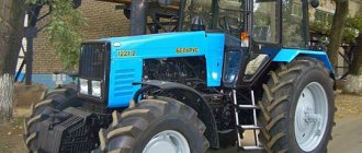
Design and operation of the starting engine of the MTZ 80(82) tractor
In the modification of the D 240 L engine of the Belarus tractor, starting is carried out using a two-stroke gasoline starting unit. Unlike electric starting, the advantage of the system is the ability to crank the diesel engine for a long time with powerful torque, which is not limited by the resource and state of charge of the batteries, which is especially important when starting a diesel engine in the cold season. The starting engine itself can be started either from an electric starter or from a manual drive using a cable wound on a special recess in the flywheel.
Device PD-10
The standard unit for the D 240 L diesel engine is the PD-10UD starting engine. Other modifications of this engine for many assembly units are unified and are used in the starting systems of tractors of the YuMZ-6L, T-150, T-150K, DT-75 brands. The single-cylinder engine, which is popularly called “Puskach”, is located on the left side of the tractor and is attached to the rear plate of the diesel engine.
The starting system consists of three parts:
- Working cylinder with crank mechanism
- A distribution gearbox that provides drive to the ignition generator - magneto, speed controller of the starting engine and a separate transmission gearbox
- The starting engine transmission, which performs the function of transmitting the created torque directly to the tractor diesel flywheel.
Technical characteristics of PD-10 UD
- Power – 7.36 kW/10 hp. ̄
- Cylinder diameter 72 mm
- Stroke 85 mm
- Volume 0.346 l
- Compression ratio 7.3
- Maximum operating time under load is up to 10 minutes.
- Gear ratio of single-stage gearbox 16.8
- Type of electric starter used ST-362
Working cylinder and crank mechanism
The cylinder is attached with its lower part to the engine crankcase. The cast iron part with inlet, exhaust and purge windows is cast with external flanges for appropriate mounting of the carburetor and exhaust pipe, as well as a flange for connecting the water cooling cavities with pipes to the diesel system.
The engine head is mounted on the cylinder through a metal-asbestos gasket on four studs. The symmetrical arrangement of the head mounting holes allows it to be installed in any convenient position when connecting the supply flange to the diesel water jacket. In the head with a combustion chamber, a spark plug is installed in the central threaded hole. Additionally, the part is equipped with a decompression valve for purging the cylinder.
The engine crankcase consists of a pair of cast parts. This design allows the use of rolling bearings for two crankshaft bearings. The crankshaft consists of two axle shafts, two cheeks with counterweights, and a crank pin. Two rollers without cages and separators are installed in the lower one-piece head of the connecting rod, and a bronze bushing with holes for the passage of lubrication of the pin connecting the connecting rod to the piston is pressed into the upper one. To prevent rotation, the piston compression rings are locked with brass pins screwed into the landing groove. A flywheel is installed at the outer end of one axle shaft; the drive gear of the distribution gearbox is installed on the other. The end of the axle shaft with the gear rests on a ball bearing, which does not allow the shaft to move in the axial direction under the acting forces of the drive gears.
The flywheel with the ring gear for the starting drive from the electric starter is fixed on the shaft with a key connection and is closed by an additional crankcase, into a special hole in which the starter is attached with two bolts. Part of the flywheel cover is removable for use with a cord starting drive.
The mechanism is lubricated with oil diluted in the gasoline supplying the engine in a ratio of 20:1. During operation, oil vapors and condensate are deposited on the parts of the unit, lubricating the rubbing surfaces.
Features of assembly and repair
The piston group of the working cylinder of the PD-10 starting unit includes two repair sizes:
| Dimensions | Industrial | Repair No. 1 | Repair No. 2 |
| Piston skirt diameter, mm | 71,82 (-0,03) | 72,57(-0,03) | 73,32(-0,03) |
| Cylinder diameter, mm | 72 (+0,03) | 72,75(+0,03) | 73,50(+0,03) |
- The connecting rod pins and mounting holes in the piston come in two sizes, marked with paint on the end of the pin and the piston boss. The smaller size is marked with white paint, the larger one with red paint.
- The pin with connecting rod is seated into the piston holes while it is hot when the piston is heated in oil to 100˚C.
- The piston is installed so that the arrow stamped on the spherical bottom of the part points towards the flywheel of the unit. This position prevents the joints of the compression rings from getting into the cylinder windows, preventing their breakage during operation.
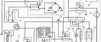
Distribution gearbox
In the composite front part of the crankcase there is a gearbox with distribution gears. From the drive gear 5 at the front end of the crankshaft, rotation is transmitted to the intermediate gear 1, which transmits torque to the starting engine transmission. At the same time, through the intermediate gear, drive is carried out through the corresponding magneto gears 4.6 and the engine regulator, which are mounted in the holes in the wall of the front part of the gearbox housing.
For correct installation of the magneto with an ignition spark advance angle of 27˚, the intermediate gear of the gearbox is installed in compliance with mark K with mark K on the crankshaft gear and mark M with the mark of the same name on the magneto drive gear.
Carburetor power system
Mixture formation is carried out due to the vacuum created by the engine. The system includes a fuel tank, carburetor, and air filter.
Starting motor PD-10: characteristics and design
One of the most important components in the design of various types of motorized equipment is the engine starting system. The reliability of operation, the speed of switching on the motor, and therefore its correct operation directly depend on it. The PD 10 launcher is installed on MTZ tractor equipment, which is rightfully considered the most common.
How the launcher works
The PD 10 starting motor is designed to ensure stable starting of the engine of MTZ tractors; it stands out among other analogues with its excellent technical characteristics and high stability of operation. It is a standard launcher equipped with one cylinder. Its working volume is 0.346 liters, which is quite enough to start the engine even in unfavorable conditions. The power of the unit at 3.5 thousand revolutions reaches 10 hp.
Having studied the technical characteristics of the product, it should be noted that it is of a two-stroke type and is equipped with a crank-chamber purge. The engine runs on a gasoline mixture, the quality of which is regulated using a carburetor, which allows for finer tuning of the engine. The operating principle of such a device is extremely simple.
First, the PD-10 is started through a standard tractor starter, after which it is connected to the main engine of the vehicle. With the help of mechanisms, rotational energy is transferred to the gearbox and, subsequently, the tractor crankshaft gains the necessary speed for stable independent operation. After the main engine has reached operating condition, the starting analogue stops operating.
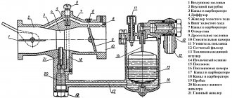
Diagram of the PD-10 starting motor
The starting motor of this brand consists of a number of components and appears to be a complex technical unit designed to ensure a stable start of the MTZ tractor engine. Studying its structure, the following key design elements can be identified:
- cylinder. Attached to the crankcase using nuts. Purge channels, strategically located tangentially to the circumference of the unit, reduce leakage of the mixture into the exhaust. The cylinder head is equipped with a spark plug;
- piston. Made from high-strength aluminum alloy. Its distinctive feature is a spherical bottom, which improves the quality of cleaning the cylinder from exhaust gas. If you want to achieve the correct position of the piston, you should place it so that the arrow on its bottom points towards the rear axle shaft of the crankshaft;
- connecting rod mechanism. Made of special grade steel, equipped with a bronze bushing. The mechanism heads are one-piece, and the bearing is double-row, roller type;
- gears;
- crankshaft. Roller bearings with rubber seals act as its support. In order to equalize the centrifugal force, the knees of the cheeks are equipped with special weights;
- The cooling system of the unit is connected to a similar system of the main motor.
These elements are key and take the most active part in the operation of this engine. At the same time, there are many other components, such as pins, rings, windows and other components.
PD-10 maintenance
As a rule, the launcher will not require much time from the owner to carry out maintenance work on the unit. It is important to remember that using fuel in its pure form, without first mixing it with oil, is strictly prohibited, as this can lead to engine damage and subsequent failure.
In order to refuel the engine, you will need to mix pure gasoline of proper quality and motor oil in a clean container, strictly observing the proportions of 15:1. When refueling, it is necessary to use a special filter funnel, which will prevent large and small contaminants from entering the internal components of the unit.
As you use it, you should wash the fuel tank sump, and promptly wash or replace the air filter. It is recommended to do this every 480 hours of use. Since many problems that arise with the starter are associated with unsatisfactory cleanliness of the air filter, it should be periodically removed and cleaned, following the following instructions:
- Remove the air purifier protective cap and limiting mechanism.
- Remove the filter.
- Rinse it in diesel fuel, then moisten it with oil.
- Install the filter, restrictor mechanism and cap.
It is necessary to pay due attention to the maintenance of the gearbox operating in conjunction with the PD-10. First of all, the oil should be changed after 960 hours of operation, and topped up every 480 hours, as needed.
The functionality of the clutch assembly should be checked at similar intervals. During operation, it is necessary to remember that the operating time of the launcher should not be more than 10 minutes, otherwise the likelihood of its failure increases significantly.
Setup and adjustment
Its technical performance, as well as the stability and efficiency of operation, depend on the correct tuning of the engine, including the PD 10u. Adjustment of the device is carried out in several stages, the first of which is considered to be setting the carburetor.
Starting motor transmission gearbox
The function of the mechanism is to switch on the rotation transmission to the diesel flywheel, as well as automatically turn it off after starting the tractor engine. The starter transmission housing is attached to the rear wall of the diesel engine and is connected to the lower plate of the distributor gearbox, receiving rotation from the intermediate gear. The mechanism is lubricated with diesel oil, filled to the level of the control hole in the gearbox housing. The level is monitored every 240 hours of operation. The oil is changed at intervals of 960 hours of tractor operation.
The device includes the following mechanisms:
- friction clutch gear
- roller overrunning clutch automatic release
- Bendix is a mechanism that controls a gear that meshes with a diesel flywheel.
- levers and clutch engagement drive,
With the help of a driver, a gear sliding along the splines of the shaft engages with the rim of the engine flywheel. The on position is held by latching weights, which are fixed by spring force. When the starting engine is running, the clutch gear does not transmit rotation to the shaft as the driving clutch discs are not connected to the driven ones.
The clutch drive drum is riveted to the gear and rotates together with the drive disks, since the drum leads fit into the grooves of the disks. The driven ones are connected by their protrusions to the overrunning clutch bushing and rotate with it.
The overrunning clutch interacts directly with the shaft and is housed in a separate bushing. The bushing itself is both the driven part of the clutch assembly and the driving race of the overrunning clutch. The operating principle consists of jamming four symmetrically located rollers spring-loaded through pushers into the wedge-shaped recesses of the bushing.
Starting motor gearbox MTZ 80
A single-stage gearbox is designed to transmit rotation from the starting engine to the diesel engine during startup, as well as to automatically turn off the starting engine when the diesel engine has started. The design of the gearbox is shown in the figure below.
Starting motor gearbox
- driven disks
- driving disks
- gear housing
- gear shaft
- springs
- pusher
- pusher bushing
- snap weights
- switch lever
- engagement gear
- flywheel crown
- clutch gear
- overrunning clutch roller
- movable stop
- fixed stop
The gearbox mechanism is mounted in housing 3, which is bolted to the rear sheet of the diesel engine.
Rotation from the crankshaft gear of the starting engine is transmitted through the intermediate gear to clutch gear 12. The gear rotates together with the drum attached to it and the driving friction discs 2 entering the slots of the drum. The gearbox shaft 4 does not rotate. Using a driver 9, the engagement gear 10 is brought into engagement with the rim of the diesel flywheel 11 and is held in the engaged position by latch weights 8, which are pressed against the sleeve 7 due to the force of the compressed springs 5.
When lever 1 is smoothly moved (see the figure in this article) to position II, the movable stop 26, sliding along the protrusions of the fixed stop 27, moves along the axis to the right and engages the clutch. After the clutch is engaged, the rollers 25 of the overrunning clutch jam and the gearbox shaft 24 begins to rotate. Rotation from the starting engine is transmitted to the diesel flywheel. When the diesel engine picks up speed, the flywheel will drive the gearbox shaft, the speed of which will increase. With increased speed of the gearbox shaft, the overrunning clutch automatically disconnects it from the running starting motor. Under the influence of increased centrifugal forces, the latch weights 21 will disperse. Their hooks will jump off the protrusions of the sleeve 19. Under the action of the springs 17 and the pusher 22, the gear 18 disengages from the flywheel ring. The gearbox will automatically disconnect from the diesel engine.
Repair and operation of MTZ » Launcher MTZ-80: device, principle of operation
Starting motor PD-10: device, circuits and principle of operation. Necessary information for repairing the MTZ-80 launcher. Location of the starting motor in the MTZ-80/82 tractor.
For all diesel engines of MMZ (Minsk Motor Plant), which produces tractors of the MTZ - 80, 82 brand and their modifications, the installation of one type of starting device is provided - PD - 10 (starting motor), consisting of a gearbox and the single-cylinder engine itself.
Among the common people and among motorists, this small motor is simply called a “starter,” although starting a tractor without it is quite problematic.
PD - 10 is a small starting, two-stroke engine with a carburetor, developing power up to 10 horsepower and installed on modified diesel units D-240L or D-243L, equipped with a centrifugal regulator operating in one mode.
This regulator is connected via a lever to the carburetor throttle valve and automatically opens/closes it, as well as a stable crankshaft speed.
Adjusting the starter gearbox MTZ 80 device
The starting engine or so-called “starter” is a small carburetor engine that is needed to facilitate starting of diesel tractors. The PD 10 starting motor has the following characteristics: its power is 10 horsepower, while the number of revolutions per minute is 3500.
When using this launcher, you should know that its operation should not exceed 10 minutes. If you force it to work for more than 10 minutes at a time and do not take care of it, then it is likely to fail prematurely.
Let's consider some malfunctions of the PD 10 starting motor that may arise during operation of the MTZ trpctor.
Operating principle of PD-10
There is nothing complicated in the PD-10 ignition system and everything is extremely primitive. However, it uses both standard spark plugs with high voltage wires and a special electric starter for starting.
The rotation of the diesel flywheel is caused by transmission of rotational movements by a gearbox with one stage using an engaging gear.
Lubrication of all working parts (gears and bearings) of the starting engine itself occurs by uniformly spraying a combustible mixture (diesel fuel mixed with oil in a ratio of 1: 1).
Repair and maintenance
To maintain tractor equipment of this type in constant working condition, it is necessary to assess the weather and climatic conditions of using the tractor and, in accordance with them, carry out regular technical inspection.
Of course, the owner can carry out almost any repair himself, but it is better to entrust all repair and maintenance work to specialists.
Maintenance of MTZ-80, 82 tractors and its modifications takes place according to a special numbering system, where regulated time intervals for passing ETO (monthly technical inspection) are established.
- Every 60 operating hours.
- Every 240 operating hours.
- Every 960 operating hours.
Naturally, if problems and malfunctions are detected during work, unscheduled work can and should be carried out in circumvention of the regulations.
Also, when operating the starting and main engines MTZ-80, 82, it is necessary to take into account seasonal changes and transitions from the spring-summer to autumn-winter period.
The MTZ starting engine gearbox (Figure 1) transmits rotation from the starting engine crankshaft to the diesel crankshaft when it is started. The main parts of the gearbox are a shaft (item 4), rotating on two ball bearings, a friction clutch, an activation mechanism and a freewheel. On the shaft (pos. 4), the clutch gear (pos. 6) rotates freely, which is constantly engaged with the intermediate gear of the starting unit.
The drive drum (item 11) of the coupling is attached to the gear with rivets, which has four projections that fit into grooves on the drive disks (item 12) of the coupling. The protrusions on the driven disks (pos. 13) fit into grooves made on a special cage of the freewheel, which is why when the disks (pos. 13) rotate, the cage also rotates. The inner surface of the cage is made with four shaped grooves. In each groove there is a cylindrical roller (item 14). The grooves of the cage are made in such a way that at the moment the clutch is engaged, when the sleeve begins to rotate, the rollers roll along the groove and clamp the cage onto the shaft.
Thus, rotation is transmitted to the shaft of the RPD-2.000 gearbox from the starting engine, as well as to the inclusion gear (item 8), which engages with the flywheel and transmits rotation to the crankshaft of the D-240 diesel engine . The gear is brought into engagement with the flywheel using a lever, which is connected through a rod system to the clutch lever. The clutch is engaged using the lever (item 1). By turning the lever, and with it the engagement roller (pos. 3), to the rearmost position (towards the flywheel), the pressure stop (pos. 16) is rotated.
When the lever (item 1) is turned in the opposite direction under the action of a spring, the pressure plate, thrust bearing and movable stop are pressed out. As the diesel engine speed increases, the weights (pos. 9) of the activation mechanism diverge under the influence of centrifugal force, and when the rotation speed reaches 750-840 rpm, the holder (pos. 10) is released. Acting through the pusher, compressed springs push the holder back and remove the gear (item) from engagement with the flywheel. The gearbox is automatically switched off. The gearbox parts are lubricated with oil, which is poured into the housing (item 7) through a hole made in the crankcase of the starting unit.
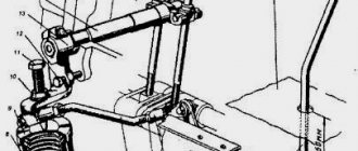
Interval MTZ-80 Device
The shafts of first gear and reverse gear belong to the same part. Clutch adjustment and braking of the MTZ tractor: 1 - support bearing; 2 — release lever; 3 — pedal lever; 4, 8 — brackets; 5 — brake rod; 6 - fork; 7 - thrust bolt; 9 - traction; 10 — bracket fastening bolt.
Because of this, slippage occurs. Removing the clutch shaft bearing retaining ring: 1 — retaining ring; 2 — clutch shaft; 3—support cover.
Very often, jamming of a broken bearing is accompanied by burning of the ends of the pressure levers. When operating the tractor, it is likely that other breakdowns and failures of the gear shift mechanisms will occur.
If the clutch drive is not adjusted correctly, which is characterized by a lack of clearance between the thrust bearing and the pressure levers, the bearing constantly rotates.
The 3rd, 4th and 5th gear drive gears are mounted on the input shaft splines.
The reverse shaft with the first gear shaft and the intermediate shaft are parallel to the primary one.
If an external inspection of the tractor reveals cracks, kinks, nicks, bends, dents and other defects that are visible without disassembling the mechanism and affecting the performance of the tractor, and when removing the units it is discovered that the technical condition of the adjacent mechanisms requires replacement or repair of a number of parts, then the units are subject to the necessary disassembly , and the parts are defective.
Dismantling the support and pressure disks: 1 - two-jaw puller; 2 — support disk; 3 - technological bolt Acceptable values of controlled diesel clutch data D, mm Thickness of the driven disk 8.0 Warping of the driven disk 0.6 Thickness of the pressure plate 21.0 Thickness of the shaft splines 3.5 Height of the release lever cam 10.9 After replacing the friction linings, the heads sink rivets must be at least 2.0 mm. Rolling out the MTZ 80 tractor
Adjusting and maintaining the cardan drive
If there is wear, be sure to replace parts. The shaft rotates on ball bearings and a bushing connected to the main gear of the second stage of the gearbox. Removing the clutch: 1 - clutch; 2 - technological bolt; 3 — support disk mounting bolt Fig. Share on facebook.
To determine whether a part can be repaired or whether it needs to be replaced, sometimes the interaction of the part with another associated part, for example, a shaft with a gear or a shaft with a housing, is checked.
If the gap is more than 3 mm, the coupling and fork must be replaced. Some boxes are also equipped with gear transmissions. Photo of MTZ tractor
If you do not replace it in a timely manner, get ready for the entire box to jam or, at a minimum, for the bearings to be destroyed. Repair and adjustment of control levers in a reduction gearbox.
Air purifier Air filter. To replace the gear coupling, roll out the core and disconnect the clutch housing from the gearbox.
Minitractor Scout T PTO repair MTZ
Disassembly and repair of the clutch and reduction gearbox of the MTZ-80, MTZ-82 tractor
How to correctly install the clutch and basket on the MTZ Different directions 11 months ago.
In such cases, the repair is carried out by the mechanic himself by replacing it. The following elements are the main elements in the fuel injection pump device:.
Vom MTZ new model. All spare parts are provided with drawing numbers of parts and assemblies.
Contents1 Grain crusher from a washing machine1. Before removing the clutch, it is necessary to tighten the technological bolts into the flywheel, thereby ensuring the initial compression of the pressure springs, see. The principle of operation is that when you press the pedal, the differential lock is activated and the rear wheels begin to work at the same rotation speed, which allows you to overcome difficult terrain. This system is located on a special flywheel, between the gearbox and the engine.
Popular videos. First stage: disconnect rod 5 from bracket 4, turn bracket 4 to the right counterclockwise until it stops; by rotating the fork 6, increase the length of the rod 5 until the fork 6 and bracket 4 are freely connected. Based on the results of the adjustment, the fork is fixed with a lock nut.