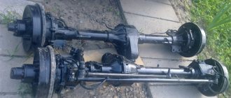
Maintenance of Kamaz bridges
The main maintenance operations for axles are checking the tightness of connections, lubricating gearboxes and adjusting bearings and gear engagement.
During maintenance, check the level and, if necessary, add oil to the drive axle housing. The oil level is checked using the control hole. If necessary, oil can be added through the same hole. After preheating the main gear, the used oil is drained through the drain holes in the axle housing. Before adding fresh oil, it is necessary to flush the breathers and clean the magnets of the drain plugs from metal deposits.
In order to reduce their axial movement, the bearings of the main gear drive gear are installed during assembly with preload, which allows maintaining the correct engagement of the bevel gear teeth under load and increases the service life of the main gear parts.
High demands are placed on the control accuracy of preloaded bearings. These works must be performed by sufficiently qualified specialists. The correct adjustment of the bearings is determined by the amount of torque that must be applied to the shafts mounted on the bearings to rotate them. The turning torque can be determined in the absence of special torque wrenches using a spring balance, which is attached to the shaft being tested on an arm of a certain radius.
The main gears also provide the ability to regulate the engagement of the bevel gears. However, it must be borne in mind that it is impractical to regulate the operating pair during operation. It is carried out when replacing a worn pair. Adjustment of bearings and bevel gear engagement is performed with the main gear removed from the vehicle.
The preload of the bearings is adjusted by selecting the thickness of the package of two adjusting washers located between the inner races of each pair of bearings on which the bevel gears rotate.
The tapered bearings of the differential housing are adjusted using adjusting nuts 34 (Fig. 1), which are tightened until the distance between the surfaces of the bearing caps increases by 0.1...0.15 mm. After this, the cover bolts are finally tightened, which creates the required amount of preload on the bearings.
The correctness of the adjustment of the bearings is checked while the vehicle is running by checking the heating temperature of the bearing installation sites. Heating should not exceed 70...80°C.
Maintenance of the front axles includes monitoring the condition of the pivot joints. To maintain the angles of inclination of the kingpins of the front drive axle of off-road vehicles, check the adjustment of the tapered bearings on the ball joint studs; if necessary, they are adjusted by changing the thickness of the shim package under the cover combined with the steering knuckle lever.
The pivot joints of vehicles with a 6X4 wheel arrangement are checked with the wheels hanging so that they do not touch the floor. The radial clearance, determined by the indicator when rocking the wheel, should not exceed 0.25 mm, the end clearance between the eye of the bridge beam and the steering knuckle should not exceed 0.25 mm.
The pivot joints must be periodically lubricated through grease nipples until fresh grease is squeezed out through the gaps between the ends of the beam eye and the steering knuckle. In this case, to ensure the release of lubricant between the lower end of the eye and the fist, it is necessary to hang the wheel above the floor.
Signs of a malfunction of the drive axle mechanisms are increased noise from the main gear when the vehicle is moving. There may also be oil leakage in the crankcase connectors and through the cuffs.
When the vehicle is moving in various modes, serviceable main gears should operate almost silently. The oil temperature in the crankcase should not exceed the ambient temperature by more than 60...70 °C. The appearance of noise during the operation of the main gear usually indicates a malfunction of the bevel gears due to wear or loosening of the bearings, as well as the appearance of excessively large lateral clearance between the teeth. One of the reasons for increased noise when driving is a lack of oil in the main gear housing. Noise that occurs when cornering often indicates a problem with the cross-axle differential. Faulty knocking noises in the final drive are associated with chipped or chipped gear teeth or damaged bearings. In the front axle of KamAZ-4310 vehicles, this phenomenon may be associated with the destruction of parts of the cam cardan joint of the front wheel drive. Continuous noise from the final drive when the vehicle is moving at high speeds is usually associated with severe wear of the gears, bearings, or lack of oil in the crankcase.
You can check the main gear malfunction based on noise using the following method. Accelerate the car on the highway from 20 to 80 km/h, and then reduce the speed by reducing the fuel supply. Note in what modes the noise appears, reaches its greatest value, and disappears. After this, accelerate the car to 80 km/h and then coast with the gearbox in neutral until it stops. A noise noticed during the first test and not repeated during the second test indicates problems with the final drive, differential, and drive axle bearings.
If, with the engine running at different frequencies, when the car is stopped in place, the noises detected during the first test are heard, then it can be stated that these noises do not relate to axles.
autoruk.ru
Bearings KamAZ - 4310 (catalog 2004)
Produced by the Kama Automobile Plant since 1989 (from 1983 to 1990, vehicles of the KamAZ-4310 family were produced). The body is a metal platform with folding rear and side sides, equipped with a frame and an awning. The flooring is wooden. KamAZ-4310 platform is equipped upon request with add-on side lattice sides with folding side and middle removable benches for transporting 30 people. The cabin is a three-seater cabin that tilts forward with a hydraulic lift, with noise and thermal insulation, without a berth (on request with a berth) and is equipped with an independent heater. The driver's seat is sprung and adjustable according to the driver's weight, length, and backrest angle. Tropical modifications are available.
Table of applicability of KamAZ bearings - 4310
| Installation location | Number | Bearing type | Size | Qty |
| Clutch (release) | 986714 (14-1601196-01) | Single angular contact ball in casing | 70x105x21/21.5 | 1 |
| Generator | 180502 | Ball radial single row | 15x35x14 | 1 |
| Generator | 180603 | Ball radial single row | 17x47x19 | 1 |
| Engine (flywheel) | 180205 (864709) | Ball radial single row | 25x52x15 | 1 |
| Engine (fuel pump driven gear) | 207 (853941) | Ball radial single row | 35x72x17 | 1 |
| Engine (fuel pump driven gear) | 305 (864713) | Ball radial single row | 25x62x17 | 1 |
| Engine (camshaft drive gear) | 97506 (740.1029118) | Roller angular contact conical double row | 30x62x50/41 | 1 |
| Engine (high pressure fuel pump injection pump) | 203 | Ball radial single row | 17x40x12 | 1 |
| Engine (power system, regulator weight coupling) | 8103 (33-1110618) | Ball thrust single | 17x30x9 | 1 |
| Engine (power system, regulator weight holder) | 106 (33-1110620) | Ball radial single row | 30x55x13 | 1 |
| Engine (power system, speed controller) | 201 (33-1110624) | Ball radial single row | 12x32x10 | 2 |
| Engine (centrifugal oil filter) | 8102 (740-1017220) | Ball thrust single | 15x28x9 | 1 |
| Engine (cooling system, water pump) | 1180304 (740-1307274-20) | Ball radial single row | 20x52x18 | 1 |
| Engine (cooling system, water pump) | 1180305 (740.1307027-10) | Ball radial single row | 25x62x21 | 1 |
| Engine (cooling system, fan drive fluid coupling) | 204 (740-1318043) | Ball radial single row | 20x47x14 | 1 |
| Engine (cooling system, fan drive fluid coupling) | 114 (740-1318174-10) | Ball radial single row | 70x110x20 | 1 |
| Engine (cooling system, fan drive fluid coupling) | 207 (853941) | Ball radial single row | 35x72x17 | 1 |
| Engine (cooling system, fan drive fluid coupling) | 305 (864713) | Ball radial single row | 25x62x17 | 1 |
| Steering (steering wheel) | 836906 | Single row angular contact ball with stamped rings | 28x44x21.5 | 2 |
| Steering (bevel gear) | 50110 | Radial single-row ball with a locking groove on the outer ring | 50x80x16 | 1 |
| Steering (bevel gear) | 110 | Ball radial single row | 50x80x16 | 1 |
| Steering (bevel gear) | 205 | Ball radial single row | 25x52x15 | 2 |
| Steering (power steering pump) | 305 (864713) | Ball radial single row | 25x62x17 | 1 |
| Steering (crosspieces) | 704902 (864710) | Needle radial single row without inner ring and separator | 15.2x28x20 | 8 |
| Steering (power steering pump) | 154901 (864714) | Needle without inner ring with separator | 12x22x16 | 1 |
| Energy accumulator | 999702 (485406) | Roller thrust with cylindrical rollers without rings, cage with rollers | 15x28x2 | 4 |
| Compressor | 207 (853941) | Ball radial single row | 35x72x17 | 1 |
| Cardan shaft of the middle bridge (crosspiece) | 804707 (4310-2205033) | Needle radial single row without inner ring and separator | 33.6x50x37 | 8 |
| Cardan shaft of the rear and front axle (crosspiece) | 804805 (5320-2201044) | Needle radial single row without inner ring and separator | 25x39x30.5 | 16 |
| Main cardan shaft (crosspieces) | 804807 (5320-2205033) | Needle radial single row without inner ring and separator | 33.6x50x31 | 8 |
| Power take-off | 307 (864748) | Ball radial single row | 35x80x21 | 2 |
| Winch gearbox | 27709 (864754) | Roller conical single row | 45x100x31.8 | 2 |
| Winch (cable laying machine) | 406 (864763) | Ball radial single row | 30x90x23 | 1 |
| Winch (cardan shafts) | 704902 | Needle radial single row without inner ring and separator | 15.2x28x20 | 8 |
| Transfer case | 50311 (864758) | Radial single-row ball with a locking groove on the outer ring | 55x120x29 | 2 |
| Transfer case (primary shaft) | 12410 (864741) | Roller radial | 50x130x31 | 1 |
| Transfer case (primary shaft) | 12312 (864759) | Roller radial | 60x130x31 | 1 |
| Transfer case (differential) | 12218 (864745) | Roller radial | 90x160x30 | 1 |
| Transfer case (differential) | 664916 (14-1701208) | Double-row needle without rings, cage with rollers | 81x92x42.5 | 2 |
| Transfer case (differential) | 50413 (864750) | Radial single-row ball with a locking groove on the outer ring | 65x160x37 | 1 |
| Transfer case (intermediate shaft) | 692409 (864779) | Roller radial with flat thrust ring | 45x120x29 | 1 |
| Transfer case (intermediate shaft) | 12409 (864780) | Roller radial | 45x120x29 | 2 |
| Transfer case (intermediate shaft) | 664913 (15.1770064-01) | Double-row needle without rings, cage with rollers | 62x70x31 | 2 |
| Transfer case (front axle drive housing) | 50310 | Radial single-row ball with a locking groove on the outer ring | 50x110x27 | 1 |
| Cabin (seat) | 108903 (864767) | Ball thrust single in casing | 17.5x32.2x10.7 | 1 |
| Wheel hubs (inner) | 7218 (864738) | Roller conical single row | 90x160x32.5 | 6 |
| Wheel hubs (outer) | 2007118 (853944) | Roller conical single row | 90x140x32 | 6 |
| Gearbox (primary shaft, rear) | 170412 (151-701032) | Ball radial single row | 60x150x35 | 1 |
| Gearbox (secondary shaft) | 592708 (141701190-01) | Roller radial with flat thrust ring | 40x77.5x23 | 1 |
| Gearbox (secondary shaft, rear) | 50412 (14-1701132) | Radial single-row ball with a locking groove on the outer ring | 60x150x35 | 1 |
| Gearbox (reverse gear unit) | 64907 (14.1701083) | Radial roller with long cylindrical rollers without rings, single row | 32x52x49 | 2 |
| Gearbox (intermediate gearbox shaft) | 12213 (14-1701066-01) | Roller radial | 65x120x23 | 1 |
| Gearbox (gear wheel of the third gear of the secondary shaft) | 664916 (14-1701208) | Double-row needle without rings, cage with rollers | 81x92x42.5 | 4 |
| Gearbox (rear intermediate shaft bearing housing) | 3610 (14-1701073) | Roller radial spherical double row | 50x110x40 | 1 |
| Front axle | 27310 (853948) | Roller conical single row | 50x110x29.3 | 1 |
| Front axle (differential) | 7216 (864720-01) | Roller conical single row | 80x140x28.3 | 2 |
| Front axle (main gear) | 27911 (864769) | Roller conical single row | 53.9x123.8x39.5 | 1 |
| Front axle (main gear) | 7214 (864724) | Roller conical single row | 70x125x26.3 | 1 |
| Front axle (main gear, drive shaft) | 102605 (804753) | Roller radial single row | 25x62x24 | 1 |
| Front axle (main gear, driven bevel gear) | 102409 (864715) | Roller radial single row | 45x120x29 | 1 |
| Front axle (steering knuckle) | 27709 (864754) | Roller conical single row | 45x100x31.8 | 4 |
| Front axle (main gear) | 7516 (864728) | Roller conical single row | 80x140x35.3 | 1 |
| Middle axle (main gear of intermediate axle) | 7214 (864724) | Roller conical single row | 70x125x26.3 | 1 |
| Middle axle (main gear of intermediate axle) | 7516 (864728) | Roller conical single row | 80x140x35.3 | 1 |
| Middle axle (main gear, driven bevel gear) | 102409 (864715) | Roller radial single row | 45x120x29 | 1 |
| Middle axle (main gear) | 12310 (864717) | Roller radial | 50x110x27 | 1 |
| Rear axle (differential) | 7216 (864720-10) | Roller conical single row | 80x140x28.3 | 2 |
| Rear axle (main gear) | 7214 (864724) | Roller conical single row | 70x125x26.3 | 1 |
| Rear axle (main gear) | 12310 (864717) | Roller radial | 50x110x27 | 1 |
| Rear axle (main gear) | 7516 (864728) | Roller conical single row | 80x140x35.3 | 1 |
| Rear axle (main gear) | 27911 (864769) | Roller conical single row | 53.9x123.8x39.5 | 1 |
| Rear axle (main gear, driven bevel gear) | 102409 (864715) | Roller conical single row | 45x120x29 | 1 |
See also:
- Bearings Gas-53 A
- Bearings KamAZ-5325
- Bearings Centaur 2060D.
- Bearings Minsk S125
- Bearings MAZ-503A
- Bearings MTT-9.
- Bearings ZIRKA SH-61
- Bearings VAZ 1111 "Oka"
- Bearings KamAZ-5425
Bridge frame and beams
The frame is the basis for fastening units, mechanisms and the car body. Trucks have side members, stamped-riveted frames (Fig. 122) consisting of channel-type longitudinal beams, called spars, and several cross members.
Rice. 122. Frame of the URAL-4320 car: 1 - tow hook; 2 — front buffer; 3,4,5,7,9 - cross members; 6, 11 — spars; 8 - rear buffer; 10 — cross member of the coupling device
Frame elements are made mainly by stamping and are connected to each other with rivets. The spars have an unequal cross-section along their length; in the middle and rear parts they have a greater height. The cross members are made of a channel or I-beam section, and on the Ural-4320 vehicle the second, third and fourth cross members are tubular. The most loaded cross members are reinforced with overlays.
In the front part of the frame, a buffer and towing hooks are attached to the side members; the footrest tilts on the front buffer. Two rear buffers and a towbar are installed on the rear cross member. In various places the frame is riveted with brackets for fastening units, mechanisms, and suspension parts.
Rice. 123. Towing device of the KamAZ-4310 vehicle: 1 — oiler; 2 — hook with a dirt deflector; 3 - latch axis; 4 - latch pawl; 5-axis pawl; 6 - latch; 7 — axle nut; 8 - chain; 9 - elastic element; 10 — hook nut; 11 — cotter pin; 12 — protective cap; 13, 14 — flanges; 15 — body; 16 — guide sleeve.
The towbar is used to connect the towing vehicle to the trailer drawbar loop. Trucks are equipped with a towbar with double-sided shock absorption and a rubber elastic element. It consists of a traction hook 2 (Fig. 123), a housing 15 with a protective cap 12, an elastic element 9, a guide sleeve 16, and fastening parts. The elastic element is installed on the rod of the hook, secured in the body with a nut 10. Preliminary deformation of the elastic element is ensured by the selection of dances 13 and 14. The hook has a latch b, which is held in the closed or open position by a pawl 4. To eliminate spontaneous disengagement, a cotter pin is inserted into the hole of the latch and pawl attached to a hook on a chain 8. The rubbing surfaces are lubricated through grease nipples 1.
Axle beams serve to transfer the weight of the sprung part of the vehicle to the wheels and transmit longitudinal, transverse and vertical forces from the wheels to the frame. On KamAZ-4310 and ZIL-131 vehicles, the beams are stamped and welded, on the Ural-4320 vehicle they are combined: the middle wide part of the beam, called the axle housing, is cast, two pipes are pressed into it, which are the housings of the axle shafts. The front axle housing of the KamAZ-4310 vehicle is molded integrally with the left short casing, the right casing is pressed into the crankcase and is held in place by rivet welding.
At the ends of the beams of the rear and intermediate axles of the KamAZ-4310 and ZIL-131 vehicles, round flanges 14 are welded (see Fig. 117) for attaching the wheel axles. For the Ural-4320 car, the wheel axles are the ends of the casings of 2 (see Fig. 120) axle shafts; on these ends there are threads cut for attaching the wheel hub. On the axle housings of the same axles of all three cars, brackets are welded for fastening parts of the rear suspension, and on the Ural-4320, in addition, there are flanges 3 for fastening the support discs of the brake mechanisms. The axle housings of the front axles of these cars end with round flanges to which the ball joints of the steering knuckles are attached.
Rice. 124. Front axle of the KamAZ-4310 car: 1 - outer hinge fork; 2 — tire tap; 3 - axle; 4 — air supply fitting; 5 — steering knuckle body; b — adjusting shims; 7 — steering knuckle lever; 8 — ball joint; 9 - internal hinge fork; 10 - plug; 11 — bottom cover; 12 — hinge fist; 13 — disk; 14, 19, 20 — bearings; 15 — brake guard; 16 — brake support disk; 17 — pad axis; 18 — oil seal; 21 — hub; 22 — centering sleeve; 23 — cylinder flange; 11 — brake drum; 12 — tube for supplying air to the tires; 13 — axle shaft; 14 — spring bracket.
The steering knuckle allows the front steered wheels to turn. It consists of a ball joint 8 and (Fig. 124) a housing with two covers (top and bottom), a pivot pin 3, fastening parts and seals. The ball joint is installed in the bridge beam and secured to it with pins; two pins are pressed and welded into its spherical surface. The steering knuckle housing is mounted on kingpins on tapered bearings. The lower bearing is closed by a cover 11, the upper bearing cover is integral with the swing arm 7. Adjusting shims are installed between the steering knuckle housing and the covers. Trunnion 6 is attached to the steering knuckle body with pins together with the support disk 16 of the brake mechanism. In the recess of the axle there is a block of air supply seals, and there are also holes for the passage of air to the tire valve 2. The tapered bearings of the pins are lubricated with the grease that is placed inside the ball joint to lubricate the constant velocity joint. Adding grease is done through the grease nipple in the upper bearing cover; the lubricant must be in a heated state, and the lubricant is replenished until it flows through the hole closed by plug 10. The lubricant is retained and prevented from contaminating the internal cavity of the steering knuckle by a rubber cuff and a felt ring enclosed in metal clips.
Fig. 125 Checking the tightness of the steering knuckle bearings
The tapered bearings of the steering knuckle are adjusted by preload; axial play in the bearings is not allowed. The bearings are adjusted by removing the spacers from under the top and bottom covers. The correctness of the adjustment is checked using a dynamometer based on the force required to turn the fist (Fig. 125). This force should be 20...30 N for KamAZ-4310 and Ural-4320 vehicles, and 20 24 N for the ZIL-131 vehicle. When checking, the bearings must be lubricated, the axle shaft removed, the bearing cap nuts tightened, and the steering knuckle seals removed.
The pivots are installed in a ball joint with an inclination in the transverse plane (by 6° for the KamAZ-4310 and Ural-4320 vehicles and by 5° for the ZIL-131 vehicle) and in the longitudinal plane of the vehicle (on the KamAZ-4310 vehicle - 1°45′, Ural-4320 - 2°11′, ZIL-131 - 3°10′). This installation of pins increases the stability of the vehicle and helps it maintain the given direction of movement.
The design of the steering knuckles also ensures that the front wheels are cambered at an angle of up to 1°. The camber is achieved by the fact that the axes of the steering axles are inclined downwards with their outer ends. Wheel camber reduces the force required to turn the front wheels, relieves the load on the outer wheel hub bearing, and promotes uniform tire wear.
The camber angles of the wheels and the inclination of the king pins on trucks are not adjustable.
Maintenance and basic malfunctions of drive axle mechanisms < Prev. Track. > Maintenance of bridge frames and beams
xn—-7sbfkccucpkracijq8iofobm.xn--p1ai
TRUCKS GAZ, ZIL, KAMAZ, URAL, MAZ, KRAZ
_________________________________________________________________________________________
Construction and adjustment of drive axles KamAZ-4310
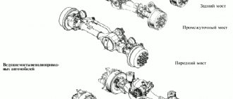
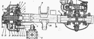
Rear axle of Kamaz-4310
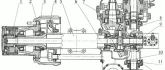
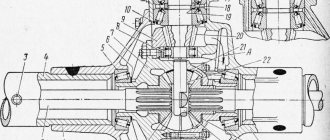
Fig.1. Rear axle KamAZ-4310 1 — locknut, 2 — wheel stud; 3 - hub; 4 — shield; 5 - fitting; 6, 11 — breathers; 7.9 — oil seals; 8 cover of the air supply seal block; 10 — spring bracket; 12 - axle shaft; 13 — brake chamber; 14 - flange; 15 — expansion fist bracket; 16- block of air supply seals; 17 - axle; 18 — brake support disk; 19, 20 — tapered bearings; 21 — brake drum; 22 - nut; 23 — lock washer; 24 - tire tap; 25 — thrust bracket; 26 — axle housing The Kamaz-4310 drive axles have double main gears, one pair of bevel gears with spiral teeth, the second pair of cylindrical helical gears; the overall gear ratio is 7.62. The design of the main gears of all three KamAZ-4310 axles is the same, however, the assembled main gears of the front, intermediate and rear axles are not interchangeable. The main parts of the Kamaz-4310 main gear (Fig. 2) are: crankcase 1, drive shaft 22 with bearings, drive bevel gear 21, driven bevel gear 2, drive spur gear 3 with shaft and bearings, driven spur gear 14.
Fig.2. Main gear and differential of the rear axle gearbox KamAZ-4310 1 - crankcase; 2 — driven bevel gear; 3 — driving cylindrical gear; 4, 6, 10, 18, 20 — tapered roller bearings; 5 - cup of bearings; 7, 19 - adjusting washer; 8, 17 — shims; 9 — adjusting nut; 11 — differential cup; 12 — cross; 13 — semi-axial gear; 14 — driven cylindrical gear; 15 - roller bearing; 16 — gasket; 21 — driving bevel gear; 22 - drive shaft; 23 — bearing cover; 24 - stopper. The intermediate and rear axle housing of KamAZ-4310 is attached to the bridge beam with a horizontal flange using studs located on the outside. There are grooves on the inner walls of the crankcase, and in the walls there are channels for the passage of oil to the bearings. There is a filler plug on top of the crankcase; the control and drain plugs are located on the axle crankcase. The drive shaft 22, together with the drive bevel gear 21 mounted on its splines, rotates in the crankcase on two bevel bearings 18 and 20 and one cylindrical roller bearing. The front tapered bearing 18 is located in the cup, the rear bearing 20 is installed in the crankcase bore.
With inner rings, bearings 18 and 20 are pressed onto the shank of drive gear 21. A flange is installed on shaft 22 for connecting the cardan drive; the shaft exit from the crankcase is sealed with a rubber cuff and an oil deflector. The driven bevel gear 2 is mounted on a shaft manufactured integrally with the drive cylindrical gear 3.
The supports of this shaft are two tapered bearings 4 and 6 located in the cup, and a cylindrical roller bearing 15 installed in the crankcase boss. The driven spur gear 14 is attached to the differential cups with bolts. The main gear of the Kamaz-4310 intermediate axle has a through drive shaft; flanges are installed at both ends for connecting cardan shafts. The main gear of the Kamaz-4310 front axle gearbox is attached to the bridge beam with a flange located in a vertical plane; the drive shaft here is non-passing and its inner end rests on a cylindrical roller bearing located inside the crankcase. When the drive shaft rotates, torque is transmitted from the drive bevel gear to the driven gear, then to shaft 4 and the drive spur gear, from where through the gearing to the driven spur gear and differential. In a bevel gear pair, the torque changes in magnitude and direction, while a cylindrical gear pair changes the torque only in magnitude. Lubrication of the main gear of the Kamaz-4310 drive axle gearbox is carried out by splashing. The Kamaz-4310 intermediate and rear axle crankcases are filled with 7 liters each, and the front axle crankcase is filled with 4.8 liters of oil. Adjusting the main gear of the KamAZ-4310 axle gearbox It is not recommended to disassemble and adjust the main gear of the KamAZ-4310 rear axle gearbox unless necessary. Bevel gears must be operated until they are completely worn out. If during operation the lateral clearance in the meshing of the bevel gears increases, adjustment should not be made, since this will disrupt the correct meshing of the bevel gears. If the increase in the lateral clearance in the meshing of the bevel gears is a consequence of wear of the tapered roller bearings, i.e. If an axial gap appears in the engagement, then the tapered bearings are adjusted. The bearings are adjusted when the main gear of the KamAZ-4310 gearbox is removed from the bridge and disassembled into components. Tapered bearings are adjusted with a slight preload; axial play is not allowed in them. Adjustment of the tapered bearings of the KamAZ-4310 drive cylindrical gear is carried out by selecting the thickness of two washers 19 installed between the inner rings of the bearings. The correctness of the adjustment is checked by the amount of torque required to rotate the shaft in the bearings. This value should be in the range of 0.8... 1.6 N. Adjustment of the tapered bearings of the Kamaz-4310 drive spur gear shaft is carried out by selecting the thickness of two washers 7 installed between the inner rings of these bearings.
The torque required to rotate the shaft of the drive spur gear after adjustment should be 1.0...3.5 N. After adjusting the preload of the bearings, the Kamaz-4310 main drive units are installed in the crankcase and the lateral clearance and contact patch of the bevel pair are adjusted. The lateral clearance equal to 0.2...0.35 mm and the contact patch between the teeth of the bevel gears are regulated by selecting the thickness of the gasket package 8 and 17, installed under the bevel bearing cups. To check the correct engagement along the contact patch, the teeth of the drive gear are painted and turned by hand in both directions while simultaneously braking the driven gear by hand. The stain remaining on the teeth of a heavy gear should have a length equal to approximately 2/3 of the length of the tooth and be located in the middle part of the tooth. The driving and driven bevel gears are selected into sets at the factory, ground in and branded, indicating the serial number of the set. Therefore, disassembly of these parts is not permitted. Differential of the KamAZ-4310 drive axle The differentials of all three KamAZ-4310 axles are conical, symmetrical, and are installed in the main gear housings on two tapered bearings each. The differential of Kamaz-4310 axles consists of two cups 11, a cross 12, four satellites with support washers, two semi-axial gears 13 with washers. The differential cups are connected to each other and to the driven spur gear to form the differential housing. The crosspiece has four spikes with which it is clamped between the cups; The flats on the crosspiece tenons serve to allow oil to pass through. The satellites are bevel gears mounted on the spikes of the spider. A bronze bushing is pressed into the satellite hole. A spherical support washer is installed between the Kamaz-4310 differential housing and the back part of the satellite. The semi-axial gears are placed in cups with their hubs and are connected to the axle shafts by splines. Flat support washers are installed between the cups and the semi-axial gears. Each side gear is in constant mesh with all four satellites. The operation of the differential of the KamAZ-4310 bridge is as follows. When a car moves straight on a level road, the wheels of one axle travel the same paths and, therefore, rotate at the same angular speed. All parts of the differential of the KamAZ-4310 axle rotate around a common axis at the same speed as the wheels; the satellites do not rotate around the axes. Torque is transmitted from the driven spur gear to the differential cups, then to the spider and satellites, which with their teeth act with equal force on the teeth of the side gears, causing them to rotate. Since the radii of the side gears are the same, the torque on the side gears will be the same. Thus, the torque between the wheels of the differential is distributed equally, which is why it is called symmetrical. When turning a corner, for example, to the left, the right wheels travel a longer distance than the left ones, therefore, they must rotate faster than the left ones. The Kamaz-4310 axle differential provides this opportunity. In this case, all differential parts rotate around a common axis and at the same time the satellites rotate around their axes, slowing down the rotation of the left side gear and accelerating the rotation of the right side gear. In this case, as much as the rotation of the left wheels slows down, the speed of rotation of the right wheels increases. If we neglect the internal friction in the differential (and it is insignificant), then the torque in this case is distributed equally. When a Kamaz-4310 vehicle slips, one wheel hits a slippery road. Due to poor traction, this wheel begins to slip and rotate faster than the second wheel. The differential contributes to this. When the left wheel is completely stopped, for example, the right wheel rotates twice as fast as the differential cups. To rotate a slipping wheel on a slippery road, a slight torque is required due to the differential’s ability to distribute torque equally; the second non-slip wheel receives the same insignificant torque. A non-slipping wheel is not able to develop the necessary traction force, move the car and continue moving. Thus, when driving on slippery roads, the differential reduces the vehicle's maneuverability. The KamAZ-4310 differential bearings are adjusted with a slight preload using nuts 24. The correctness of the adjustment is checked by the amount of deformation of the crankcase when tightening the adjusting nuts. Pre-tighten the bolts securing the 23 bearing caps to a torque of 100...120 N, then by tightening the adjusting nuts, ensure such a tension in the bearings that the distance between the ends of the bearing caps increases by 0.1...0.15 mm. Axle shafts and beams of KamAZ-4310 bridges KamAZ-4310 axle shafts are completely unloaded, i.e. transmit only torque and do not perceive vertical, longitudinal and transverse forces. The axle shafts are located in the casings of the bridge beams (Fig. 1). The inner end of the Kamaz-4310 axle shaft has splines with which it is connected to the differential side gear, the outer end ends with a flange with which the axle shaft is attached to the wheel hub 3 using studs and nuts. To center the axle shaft relative to the hub, split conical bushings are installed in the flange holes. The KamAZ-4310 axle shaft has a neck for installing a seal block 16 for supplying air to the tire, as well as radial and axial drilling for the passage of air to the tire valve 24. The exit of the axle shaft from the bridge beam is sealed with an oil seal 9. Kamaz-4310 bridge beams are used to transfer the weight of the sprung part to the wheels and transmission from the wheels to the frame of longitudinal, transverse and vertical forces. On Kamaz-4310 vehicles, the beams are stamped and welded. The front axle housing of the Kamaz-4310 vehicle is molded integrally with the left short casing, the right casing is pressed into the crankcase and is held in place by rivet welding. At the ends of the beams of the rear and intermediate axles of KamAZ-4310, round flanges 14 are welded (see Fig. 1) for attaching the wheel axles.
Brackets for attaching rear suspension parts are welded to the axle housings of the same axles of all three cars. The housings of the axle shafts of the front axles of KamAZ-4310 end with round flanges, to which the ball joints of the steering knuckles are attached. Front axle KamAZ-4310
Fig.3. Front axle of the KamAZ-4310 1 - outer hinge fork; 2 — tire tap; 3 - axle; 4 — air supply fitting; 5 — steering knuckle body; b — adjusting shims; 7 — steering knuckle lever; 8 — ball joint; 9 - internal hinge fork; 10 - plug; 11 — bottom cover; 12 — hinge fist; 13 — disk; 14, 19, 20 — bearings; 15 — brake guard; 16 — brake support disk; 17 — pad axis; 18 — oil seal; 21 — hub; 22 — centering sleeve; 23 — cylinder flange; 11 — brake drum; 12 — tube for supplying air to the tires; 13 — axle shaft; 14 — spring bracket. The Kamaz-4310 steering knuckle provides the ability to turn the front steered wheels. It consists of a ball joint 8 and (Fig. 3) a housing with two covers (top and bottom), a pivot pin 3, fastening parts and seals. The ball joint is installed in the beam of the KamAZ-4310 bridge and is attached to it with pins; two kingpins are pressed and welded into its spherical surface. The Kamaz-4310 steering knuckle body is mounted on kingpins on tapered bearings. The lower bearing is closed by a cover 11, the upper bearing cover is integral with the swing arm 7. Adjusting shims are installed between the steering knuckle housing and the covers. Trunnion 6 is attached to the steering knuckle body with pins together with the support disk 16 of the brake mechanism. In the recess of the axle there is a block of air supply seals, and there are also holes for the passage of air to the tire valve 2. The tapered bearings of the Kamaz-4310 king pins are lubricated with the lubricant that is placed inside the ball joint to lubricate the constant velocity joint. Adding grease is done through the grease nipple in the upper bearing cover; the lubricant must be in a heated state, and the lubricant is replenished until it flows through the hole closed by plug 10. The lubricant is retained and prevented from contaminating the internal cavity of the Kamaz-4310 steering knuckle by a rubber cuff and a felt ring enclosed in metal clips. Adjustment of the tapered bearings of the Kamaz-4310 steering knuckle is carried out by preload; axial play in the bearings is not allowed. Adjustment of Kamaz-4310 bearings is carried out by removing the gaskets from under the upper and lower covers. Correct adjustment is checked using a dynamometer based on the force required to turn the fist. This force should be 20...30N. When checking, the bearings should be lubricated, the axle shaft removed, the bearing cap nuts tightened, and the steering knuckle seals removed. The pivots are installed in a ball joint with an inclination of 6° in the transverse plane and 1°45 in the longitudinal plane of the vehicle. This installation of pins increases the stability of the vehicle and helps it maintain the given direction of movement. Constant velocity joints (CV joints) Kamaz-4310 Constant velocity joints (CV joints) Kamaz-4310 are cam-type, installed in the drive on the front steered wheels, located inside the steering knuckles (see Fig. 4) of the front axle. The Kamaz-4310 CV joint consists of two forks 1 and 5, two knuckles 2 and 4 and a disk 3. When turning and rotating the wheel, the knuckles rotate relative to the forks and at the same time relative to the disk, which ensures the transmission of rotation from the inner fork to the outer one at the same angular speed. Fig.4. Constant velocity joints (CV joints) KamAZ-4310 a - cam; b - ball: 1 - outer plug; 2,4,6,7 - fists; 3 — disk; 5 - inner plug; 8 — driving balls; 9 - centering ball. Lubrication of the Kamaz-4310 CV joint is provided by oil poured into the steering knuckle housing. 3.0 liters of a mixture of Litol-24 lubricant and TSp-15K oil (50% each) is placed into the cavity of each hinge.
_________________________________________________________________________________________
- GAZ-3307 clutch maintenance
- Steering system GAZ-3307
- Gearbox parts for GAZ-3307
- Maintenance of the rear axle GAZ-3307
- Maintenance of the fuel system of the D-245 diesel engine
- Clutch GAZ-3309 with a diesel engine
- Operations for disassembling the GAZ-3309 gearbox
- GAZ-3309 front axle service
- Repair of cardan shafts of GAZ-3309 cars
_________________________________________________________________________________________
_________________________________________________________________________________________
- Operations for assembling basic components of the ZIL-130 engine
- Service and repair operations for the ZIL-130 gearbox
- Maintenance and repair of ZIL-130 clutch
- Repair and adjustment of the rear axle ZIL-130
_________________________________________________________________________________________
- KAMAZ-4310, 43118, 43114
- KAMAZ-5320, 55111, 53212, 5511, 55102
- KAMAZ-65115, 6520, 65117
- KAMAZ-4308
- Engine KAMAZ-740
_________________________________________________________________________________________
- Parts of the cylinder block and head of the YaMZ-236 engine
- Service maintenance of the YaMZ-236 piston group and crankshaft
- Diagnostics and technical adjustments of the YaMZ-236 engine
- Design and adjustment of fuel injection pump and injectors of the YaMZ-236 engine
- Cylinder block and piston YaMZ-238
- Components of the YaMZ-238 diesel fuel supply system
- Design and adjustment of the fuel injection pump of the YaMZ-238 diesel engine
- Technical design of the YaMZ-239 gearbox
_________________________________________________________________________________________
- Components of the front axle and steering rods of the Maz-5516, 5440
- Steering system of Maz-5516, 5440 cars
- Clutch and gearbox parts Maz-5516, 5440
- Maintenance of drive axles of MAZ-5516, 5440 vehicles
- Power steering for Maz-5551, 5335 cars
- Maintenance of cardan transmission of Maz-5551, 5335 cars
- Maintenance and adjustment of clutch MAZ-5551, 5335
- Repair and service of the rear axle of MAZ-5551, 5335 cars
_________________________________________________________________________________________
- Gearbox Ural-4320
- Construction and adjustment of Ural-4320 bridges
- Maintenance of transfer case Ural-4320
- Steering components Ural-4320
_________________________________________________________________________________________
- Servicing the KRAZ-255, 260 gearbox
- Steering mechanism and power steering Kraz-255, 260
- Adjustments and repairs of the power steering cylinder and steering rods of the Kraz car
- Drive axle components and drive shafts Kraz-255, 260
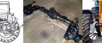
Assembly of the front axle KAMAZ all-terrain vehicle
We disassemble the KamAZ 4310 bridge
Repair of the steering knuckle (fork) assembly of the front axle of KamAZ 6522. MADARA bridge. Part III
Ural 4320. Repair part 24, front axle assembly.
Repair of the steering knuckle (fork) assembly of the front axle of KamAZ 6522. MADARA bridge. Part I
Ural 4320 part 20. Repair, disassembly of the steering knuckle, removal of axle shafts.
Ural 4320 part 21. Repair, replacement of ring bushings, steering knuckle seals.
Assembling the KamAZ steering knuckle
Ural timber carrier replacing axle shaft in the field
KAMAZ — Rear axle gearbox repair — Part 5 — Differential assembly
Ural 4320. Repair part 33.
Also see:
- KAMAZ number of horses
- The pre-heater on KAMAZ does not turn on
- KAMAZ axle stud
- KAMAZ typhoon parade
- KAMAZ 4310 left door
- Engine KAMAZ 53229 mixer
- All KAMAZ grain truck models
- Trailer for KAMAZ video
- Cargo transportation KAMAZ with a grain truck trailer
- Interesting video about KAMAZ trucks
- Manovsky engine for KAMAZ
- Spare parts for gas KAMAZ
- KAMAZ accident on Friday
- Heating and ventilation unit KAMAZ
- Head gasket for KAMAZ Euro engine
Home » Choice » Assembly of the front axle KAMAZ all-terrain vehicle
kamaz136.ru
Front gearbox KamAZ 43118 diagram
Quick links (click): Price for KamAZ 43118 front gearbox DELIVERY IN RUSSIA 6 MONTHS WARRANTY
WATCH A VIDEO!!!
Front gearbox KamAZ 43118 diagram
———————————————————————————————————————————————————————
————————————————————————————————————————————————————
Front gearbox KamAZ 43118 diagram
Reduktor-Kama specializes in: - trade in spare parts for KAMAZ tractors; — trade in new main gears produced by KAMAZ; — repair of KAMAZ main gears (experienced workers will carry out high-quality repairs, you will be happy); — sale of repair KAMAZ gearboxes, mounted from newly produced parts on a used body (why overpay for a new gearbox produced by KAMAZ OJSC, when the main gears we assemble will last no less than the original KAMAZ ones).
We ship KamAZ 43118 front gearbox diagram throughout the Russian Federation: Liski. Khanty-Mansiysk Prokopyevsk Dnepr Nalchik. Lipetsk Yakutsk Volkhov. Lyubertsy Cheboksary. Tula Chisinau Ryazan Chernigov Kokshetau St. Petersburg Bryansk Podolsk Samara Chekhov Langepas Usinsk Irkutsk Kimry Kropivnitsky Simferopol Nizhny Novgorod Taishet Salekhard Labinsk Solnechnogorsk Khabarovsk. Kumertau Ust-Ilimsk Tuapse Voskresensk Nefteyugansk Dedovsk Uman Nizhnyaya Tura Velikiye Luki Voronezh Biysk Lomonosov Serpukhov Ekaterinburg Kyzyl Almaty Tomsk Slavyansk Zhirnovsk Arzamas Taganrog Kostroma Astana Novy Urengoy Miass Vsevolozhsk Perm Yelets Tuymazy Kramatorsk Semikarakorsk Grozny Nad y Yoshkar-Ola Novokuznetsk Iskitim Belorechensk. Domodedovo Mytishchi Tambov Krasnoyarsk Mineralnye Vody Verkhnyaya Salda Veliky Novgorod Makhachkala Melitopol Gomel Elista Saransk Syktyvkar Vinnitsa Kursk Kharkov Volzhsky Krasnoturinsk Norilsk Orsk Sergiev Posad Stavropol Chita. Smolensk Krasnodar Lisichansk Yaroslavl Klin Berdyansk Magnitogorsk Magadan Volgodonsk Kherson. Inta Verkhnyaya Pyshma Rudny Vidnoye Ulan-Ude Petropavlovsk Kostanay Temryuk Sestroretsk Tver Buzuluk. Lobnya Angarsk Vladivostok Severodonetsk Nikolaev Murmansk Belgorod Kandalaksha Nizhnevartovsk Nyagan Barnaul Ufa. Zelenograd Murom Omsk Yeniseisk Aktobe. Orel Kemerovo Reutov Bratsk. Cherkassy Izhevsk Saratov Dmitrov Lesosibirsk Nizhny Tagil Soviet Volgograd. Togliatti Vologda Voznesensk Glazov Uralsk Pskov Olenegorsk Noyabrsk Kirov Kurgan Sochi Malin Zlatoust Stary Oskol Poltava Chelyabinsk Atyrau. Achinsk. Sizran. Mines Ukhta Novorossiysk Shebekino Rostov-on-Don Aldan Kogalym. Dimitrovgrad Segezha Vladimir Berdsk Balashikha Komsomolsk-on-Amur Oktyabrsky Blagoveshchensk Zaporozhye Penza Mikhailovka Khimki Kotlas Ivanovo. Georgievsk Gelendzhik Astrakhan Orenburg Rossosh Naryan-Mar Karaganda Arkhangelsk. Nevinnomysk Vladikavkaz Ussuriysk Dzerzhinsk Orekhovo-Zuevo Sterlitamak Kropotkin Koliningrad Brovyari Kazan Petrozavodsk Minsk Kaluga Neftekamsk, Moscow Abakan-Sakhalinsk Armavir Grodno Novosibirsk Lukhovitsa Kirensk Kirenski Khukovsky crook Zhukovsky Zhukovsky Zhukovsky Zhukovsky Rog Satka. Aleksandrov Surgut Ulyanovsk Sumy Tyumen Chernivtsi Troitsk Mirny Sovetsk Salavat, etc.