Currently, wheeled bulldozers DZ-37 (D-579) class are produced. 1.4 tf; DZ-48 (D-661) class. 6 tf; crawler bulldozers DZ-29 (D-535) and DZ-42 (D-606) class. 3 tf; DZ-101 and DZ-104 class. 4 tf; DZ-53 (D-686), DZ-54S (D-687S), DZ-27S (D-532S), DZ-17 (D-492A), DZ-18 (D-493A), DZ-109 and DZ -POHL class. 10 tf; DZ-24A (D-521A), DZ-35S (D-575S) class. 15 tf; DZ-34S (D-572S) and DZ-118 class. 25 ts. Wheeled bulldozers DZ-102 class are being mastered. 1.4 tf, crawler bulldozers on T-330 tractors (DZ-59HL and DZ-60HL) class. 25 tf and T-500 (DZ-64S).
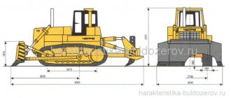
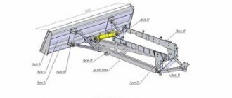
Rice. 2.4. Bulldozer with a rotary blade and hydraulic drive D3-109HL 1 - blade; 2 - pusher; 3 - universal frame; 4 - tractor
The technical characteristics of bulldozers are given in table. 2.2; 2.3 and 2.4. The general view of the bulldozer is shown in Fig. 2.4.
The main components of the bulldozer are the blade, the pushing device and the blade control system.
The blade (Fig. 2.5) is a welded structure consisting of a front sheet, a visor, lower and upper stiffening boxes, ribs welded to the lower stiffening box, side walls and eyes that serve to connect the blade to the pushing device.
Rice. 2.5. Bulldozer blade
The frontal sheet is welded from two sheets: the upper one, bent along a radius of a certain curvature, and the lower one, straight, located obliquely to the horizon, usually at an angle of about 60°. Replaceable knives are bolted to the bottom sheet: two outer ones and one middle one, which have double-sided sharpening, which allows them to be turned over or swapped as they wear out. The lower box is made of sheet steel, usually in the form of a triangular prism. The top box is a square beam. The vertical rigidity of the blade is created by the connections. Eyes are welded at the back of the blade to attach it to the push bars and braces. Extenders can be installed on the side cheeks of the blade to increase the volume of soil being swept.
Table 2.2
A visor, reinforced with ribs, is welded to the top of the front sheet, preventing it from overflowing through the blade during lifting and pushing.
For bulldozers of the 3 tf class (DZ-29, DZ-42, etc.), a bracket is welded to the back in the middle of the blade for a swivel connection with the hydraulic cylinder rod, the head of which is equipped with a ball bearing. The blade of fixed bulldozers of the 10 tf class (DZ-54) is equipped with eyes for connection with hydraulic cylinder rods, push bars and braces. Rotary bulldozers of the 10 tf class (DZ-18) have a ball socket for connection with the ball preparation of the pushing frame, equipped with a plate. To connect the blade with the pushers, use lugs with pins. For rotary bulldozers of the Shts class (DZ-25), the blade, instead of a ball socket, is equipped with an eye that covers the head of the universal frame and is hinged to it with a vertical pin. The blade has additional eyes at the edges for connection with the hydraulic cylinder rods for turning the blade in plan.
Table 2.3 Technical characteristics of crawler rotary bulldozers
Pushing bars or a pushing frame are used as a pushing device. For bulldozers with a fixed blade, the blade is attached to two push bars located on the right and left sides of the tractor (tractor). Push bars are rectangular or circular beams with lugs designed for mounting a blade and braces, as well as for attaching bulldozer equipment to the base machine.
Table 2.4 Technical characteristics of wheeled bulldozers
For non-rotating bulldozers, the connection between the blade and the beams can be rigid or articulated. In the first case - for bulldozers of the 3 tf class (DZ-29, etc.) - the push bars are welded to the blade. Fork catchers are welded to their opposite ends. Using catchers and pins, the push bars are pivotally connected to cylindrical pins at the ends of the transverse beam. A transverse beam of trapezoidal cross-section is attached in the middle of the tractor to the frame side members using two stepladders and stops that prevent it from moving in the longitudinal direction.
In the second case - for bulldozers of the 10 tf class (DZ-54, etc.) - the blade with the push bars is connected using screw braces of a tubular section, providing a slight change in the cutting angle (within 10°) and the transverse skew angle (within 4° ). To connect with the support hinges of the push bars, plates with support pins are installed on the frames of the crawler bogies. The 25 tf class bulldozer (DZ-34S) has spherical support joints for push bars.
Rice. 2.6. Universal shackle: 1 - half frame; 2 — bracket for connecting the pushers; 3 - eye for connection to the hydraulic cylinder rod; 4 - ball head; 5 — eye for connecting blocks to the frame; 6 — frame eye; 7 - support
For bulldozers with a rotary blade, the pushing device is made in the form of a pushing frame. Since other replaceable working parts (brush cutter, uprooter, etc.) can be installed on the frame in addition to the bulldozer blade, the frame is called universal.
The universal frame (Fig. 2.6) is a uniform horseshoe-shaped structure consisting of two box-section semi-frames connected by a sheet and a ball head. To connect to the hydraulic cylinder rods, lugs are welded on top of the semi-frames. The eye serves to connect the frame to the block frame. Brackets are used to connect the frame to the pushers. With legs welded to the track frames, the frame is connected by lugs and pins. DZ-109HL bulldozers use ball joints for these purposes.
Rice. 2.7. Pusher. 1 - cross; 2 - finger; 3 — brace screw; 4 - liner; 5 — brace pipe; 6 — handle; 7 - eye; 8 — pusher screw; 9 - timber
Rice. 2.8. Scheme of the bulldozer rope drive: 1 - winch; 2 - pneumatic cylinders; 3 — tractor power take-off shaft; 4 — winch control handle; 5 — guide blocks; 6 — pulley block; 7 - drum with spare rope
Pushers (Fig. 2.7) are made in the form of bars of box-shaped or tubular cross-section and screw braces. The braces are interconnected by hinge joints, providing the ability to change the distances between the attachment points to the frame and the blade. The pushers are connected to the eyes on the blade using fingers and crosses. An insert with an internal thread is welded into the brace pipe at the front, and a bushing with an eye at the rear. In the middle, a handle passes through the brace pipe, with the help of which the length of the brace is changed. The threaded part of the brace screw is protected from dust by a seal.
Using a screw with a fork, the beam is connected to a kingpin mounted in a bracket on the frame. Changing the cutting angle and skew of the blade in one direction or another is done by manually changing the length of the pusher braces, and changing the plan angle is done by rearranging the pusher pins in various brackets on the frame.
The main working movements of a bulldozer consist of lowering and raising the blade. These operations are controlled using a rope or hydraulic drive.
The diagram of the rope drive is shown in Fig. 2.8. The drive consists of a winch and a system of blocks that serve to supply the rope from the winch to the blade and form a pulley, which increases the traction force of the winch several times. Bulldozers usually have single-drum winches, which are installed on the rear axle of the tractor and are driven from the power take-off shaft through the connecting shaft. For bulldozers with a cable-block control system, for installing block clips, a front pillar is equipped, consisting of two vertical beams connected to each other at the top by a transverse beam, and at the bottom by a strip. To protect the radiator, a shield is attached to the front of the rack.
Rice. 2.9. Diagram of the bulldozer hydraulic drive: 1 - hydraulic distributor; 2 - metal pipelines; 3 — adapter pipe, 4 — high-pressure hoses; 5 — hydraulic cylinders for raising and lowering the blade; 6 — hydraulic cylinders for turning the blade in plan; 7 — hydraulic cylinders for blade skewing
If there is a hydraulic drive, the raising and forced lowering of the blade is carried out using hydraulic cylinders. The diagram of the hydraulic drive of the bulldozer is shown in Fig. 2.9. The drive operates from the hydraulic system of the base tractor through a hydraulic distributor, a pipeline system, flexible high-pressure hoses and hydraulic cylinders.
Double-acting hydraulic cylinders provide lifting and lowering of the blade, its fixation in the required position and the so-called floating position of the blade, in which, under the influence of its own weight, the blade can take any position, resting with knives on the ground surface.
In rotary bulldozers, along with raising and lowering the blade, the operations of transverse distortion of the blade and rotation of the blade in plan are hydraulically activated.
An autonomous control system of the “Autoplan” type has been created for bulldozers, which does not require the use of external guides (Fig. 2.10) and ensures stabilization of the given angular position of the blade push bar in the longitudinal plane. This system is installed on commercially produced bulldozers of the 10 tf class (DZ-18, DZ-54) and on bulldozers of the 4 and 25 tf class being developed.
Depending on the slope of the surface, the angle of inclination of the push bar is set on the control panel, corresponding to the position of the cutting edge of the knives at the level of the supporting surface of the tracks. When the angle of inclination of the push bar changes, the angular position sensor sends an electrical signal to the control unit. This signal is converted and supplies current to the corresponding electric spool, as a result of which the working fluid enters the corresponding cavity of the hydraulic cylinders for raising and lowering the blade.
Rice. 2.10. Diagram of the automatic control system for the Autoplan type blade of the DZ-54 bulldozer: 1 - drain pipeline into the tank; 2 - pipelines for supplying liquid under pressure; 3 - check valve with throttle; 4 — pipeline for supplying liquid under pressure; 5 — engine speed sensor; 6 — pendulum angular position sensor; 7 — control panel; 8 - overload block; 9 — control unit; 10 - battery; 11 — reversible electric spool; 12 - drainage pipeline
Bulldozers can be equipped with various types of replaceable equipment. These include extenders, openers, a protruding middle knife, ripper teeth, brush-cutting knives, and slope planners.
Read the diploma on transport, cargo transportation: “Bulldozer DZ-109” Page 1
(Back)
The “read” function is used to familiarize yourself with the work. The markup, tables and pictures of the document may be displayed incorrectly or not in full!
Introduction The purpose of this work is to acquire and consolidate knowledge of the design of specific components, mainly the electrical equipment of machines for excavation work.
Bulldozers are now being developed to work on harder soils. Bulldozers with increased unit power of machines and equipment are being developed. They strive to reduce the material and energy consumption of machines, increase service life and reliability, as well as use new materials with better physical and mechanical properties and characteristics; increasing requirements for the ergonomics and technical aesthetics of the machine based on a more complete consideration of the physical and financial capabilities of the operator; automation of control systems, monitoring, and ensuring the safety of machine operation; increasing movement speeds, which increases productivity; designing machines and equipment from standardized blocks, which will shorten the process of creating machines and reduce downtime for repairs.
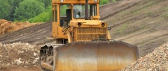
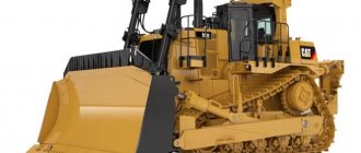
All these innovations will increase the pace of development of other sectors of the national economy and reduce the construction time of various agricultural structures. 1. General information about the machine The first tractor, the DZ-109 bulldozer based on the T-170 tractor, rolled off the assembly line in the spring of 1988 and immediately proved itself only on the positive side, and a little later the bulldozer became the most popular special equipment.
The technical characteristics of the DZ-109 bulldozer based on the T-170 tractor are at a very high level, and it is thanks to such technical indicators that it has gained its popularity.
The DZ-109 bulldozer based on the T-170 tractor belongs to traction class 10 and can be used both in the tropics and in the Far North.
The DZ-109 Bulldozer based on the T-170 tractor is equipped with 2 types of engines: D 160 and D 180.
D 180 represents a newer and modernized engine model
D-160, the power of this engine is 180 horsepower (d 160 - 160 hp). The torque reserve also increased by 25% compared to the engine of the older model. The use of the D 180 engine on the T-170 tractor significantly increases its technical characteristics. When developing new models of tractors, ChTZ adheres to the principle of continuity, which makes it possible to provide spare parts for ChTZ tractor models discontinued from main production.
The tractor is equipped with a frame cabin, which is installed on a vibration-isolated platform; the cabin has a modern design. The large glass area increases the operator's visibility.
| General characteristics of the D-109 bulldozer based on the T-170 tractor | |
| Structural weight, kg | 15000 |
| Chassis type | crawler |
| Traction class | 10 |
| Base, mm | 2517 |
| Track, mm | 1880 |
| Engine | |
| Engine make | D180.111-1(D-160.11) |
| engine's type | Four-stroke diesel, turbocharged, multi-fuel |
| Engine power, kW (hp) | 125 (170) |
| Specific fuel consumption, g/kW*h (g/l.s.h.) | 218 (160) |
| Refill containers | |
| Fuel tank, l | 300 |
| Cooling system, l | 60 |
#G0 earth moving machines (bulldozers, scrapers, graders) bulldozers
#G0EARTHING AND TRANSPORTING MACHINES (BULLDOZERS, SCRAPERS, GRADERS)BULLDOZERSA bulldozer is an earth-moving and transport machine based on a caterpillar tractor or wheeled tractor with replaceable attachments for layer-by-layer development and movement of soil (Fig. 1). The equipment consists of a blade - a frontal shield with side flaps, a frame and a blade control mechanism. Bulldozers with fixed and rotary blades are used. The fixed blade is mounted permanently perpendicular to the longitudinal axis of the tractor, and the bulldozer can only move soil in front of the blade. For bulldozers of the second type, the blade can be rotated in any direction and installed at an angle of 60° relative to the longitudinal axis of the tractor and tilted by 6... 10° in the vertical plane. Such a bulldozer can move soil to the side and perform rough leveling work, i.e. it has great technological capabilities. In the transport position, the blade is raised, in the working position it is lowered onto the base and when the bulldozer moves, it crashes into the ground. By type of drive, bulldozers come in mechanical, hydraulic and diesel-electric drives. Bulldozers primarily use hydraulic pumping and electrical control systems. According to the type of blade control, bulldozers are divided into cable-controlled and hydraulically controlled. More effective is hydraulic control, which ensures forced deepening of the blade, whereas with rope control it lowers to the ground only under the influence of its own weight. The dump is designed in such a way as to ensure the most efficient development, accumulation of soil into a prism and its movement. As the bulldozer moves, the cut layer of soil accumulates until it reaches the top of the dump. In the transport position, the blade rises to the surface of the soil, cutting off irregularities or filling depressions with soil, and leveling the surface occurs. If the bulldozer fills the embankment layer by layer, then the dump is located at a distance from the base equal to the thickness of the layer being filled.
Fig.1.
Bulldozer: 1
- pushing frame;
2
- braces;
3
— hydraulic motor for blade skew;
4
— hydraulic motor for raising and lowering the blade;
5 - blade; 6
- basic tractor
Scope of application of bulldozers: development and movement of soil over a distance of up to 100 m when constructing road and railway embankments from reserves, construction of dams, construction of pits and canals, site planning and finishing of earthworks. In addition to these basic works, the bulldozer can perform numerous preparatory, auxiliary and maintenance work. This includes clearing construction sites, clearing roads and airfields of snow, removing garbage, etc. Bulldozers also work in conjunction with other earth-moving machines, performing, for example, layer-by-layer leveling of soil for compaction when filling embankments with dump trucks. They are also used as scraper pushers when collecting soil. For this purpose, the bulldozer blade is equipped with an additional attachment - a pushing frame. Powerful bulldozers have rippers as attachments, which significantly expands their scope of application, allowing them to be used in dense and frozen soils.
Such a wide range of applications for bulldozers has made these machines the most common (along with excavators) in construction. They carry out about 40% of the total volume of earthworks. Depending on the technical and technological characteristics of earthen structures and the types of work performed, bulldozers are subject to various production requirements and machines are used that meet these requirements with power, running equipment, type of drive, the presence of attachments and other technical characteristics (Tables 1, 2). The main parameter of a bulldozer is the traction class or traction force of the base tractor (tractor). Three groups of bulldozers are most widespread in construction: 1) light ones, with a traction force of up to 60 kN; 2) medium, with a traction force of 100...150 kN; 3) heavy, with a traction force of 250 kN and above. Machines of the first group are used mainly as components for auxiliary and household work, and in small-sized versions - in cramped conditions. Machines of the second group are used for basic work when developing soils of the first - third groups (with rippers and denser ones), and heavy bulldozers perform basic work at large sites and in areas with extreme natural conditions. For example, in the group of heavy bulldozers on tractors of traction class 25, the DZ-118 bulldozer with an electromechanical transmission and hydraulic drive is common, which ensures raising and lowering the blade to the required height or depth and changing the cutting angle. The bulldozer is equipped on the basis of an industrial tractor DET-250M with a power of 243 kW. This power allows you to develop soils of any category, including frozen and blasted rocks.
Table 1
Crawler bulldozers with fixed blade #G0Indicator
| DZ-29 | DZ-42 DZ-42A DZ-42G DZ-42G-1 | D-101 | DZ-101A | DZ-130 | DZ-53 (D-685) | DZ-54S (D-687S) | DZ-27 | DZ-110 DZ-110HL | DZ-110A DZ-110-AHL | DZ- 110A-G*** | ||||||||
| 1 | 2 | 3 | 4 | 5 | 6 | 7 | 8 | 9 | 10 | 11 | 12 | |||||||
| Basic tractor | T-74 | DT-75MR-S2, DT-75NR-S2, DT-75M-S2 | T-4AP1 | T-CHAP2-S1 | T-90 | T-100M | T-100 MGP | T-130 | T-130 | T-130.1G-1 | T-130MG-1 | |||||||
| Engine power, kW | 59 | 59 | 96 | 96 | 66 | 80 | 80 | 118 | 118 | 118 | 118 | |||||||
| Nominal traction force* of the tractor, tf | (3) | (3) | 6(4) | 6(4) | (3) | 10 | 10 | 10 | 10 | 10 | 10 | |||||||
| Blade, parameters, mm: | ||||||||||||||||||
| length | 2560 | 2520-2560 | 2860 | 2860 | 2560 | 3200 | 3200 | 3200 | 3220 | 3220 | 3220 | |||||||
| height | 800 | 800 | 990 | 1050 | 800 | 1110 | 1100 | 1100 | 1150 | 1180 | 1300 | |||||||
| climb | 600 | 600 | 650 | 860 | 810 | 900 | 850 | 800 | 900 | 995 | 995 | |||||||
| lowering | 200 | 300-410 | 310 | 435 | 350 | 1000 | 370 | 335 | 500 | 465 | 400 | |||||||
| Angle, degrees: transverse cutting | 55 — | 55 — | 55 6 | 55 12 | 55 12 | 55 4 | 55 4 | 55 4 | 55 6 | 55 12 | 55 12 | |||||||
| Method for changing the skew angle | — | — | Manual | Hydraulic | Manual | Hydraulic | ||||||||||||
| Working body control | — | Hydraulic | Ropeway | Hydraulic | ||||||||||||||
| Weight, kg: total bulldzer equipment with tractor | 780 6560 | 890-1070 7000-7085 | 1000 9820 | 1600 9900 | — 8450 | 2120 14100 | 1710 13710 | 1850 13350 | — 16300 | 1990 16020 | 2055 16000 | |||||||
| Replacement equipment, equipment features | Expanders or openers | — | — | 2 | — | — | — | — | — | — | ||||||||
| Hydraulic system capacity, l | 50 | 50 | 106 | 100 | 50 | — | 65 | 140 | 140 | 140 | 140 | |||||||
| Index | DZ-110A2 | DZ-110V (DZ-171.1) | DZ-35 (D-575) | DZ-35S (D-575S) | DZ-34S | DZ-118 | DZ-132-1 | DZ-50HL | DZ-124HL | DZ-141HL | DZ-120** | |||||||
| 1 | 2 | 3 | 4 | 5 | 6 | 7 | 8 | 9 | 10 | 11 | 12 | |||||||
| Basic tractor | T-130M G-1 | T-130G1 (T-1 70.01) | T-1 80 | T-180G | DET-25 | DET-250M | DET-250M2 | T-330 | T-330 | T-500 | T-130.1 G.1 | |||||||
| Engine power; kW | 118 | 118(125) | 133 | 133 | 222 | 243 | 243 | 244 | 244 | 368 | 118 | |||||||
| Nominal traction force* of the tractor, tf | 10 | 10 | 15 | 15 | 25 | 25 | 25 | 25 | 25 | 35 | 10 | |||||||
| Blade, parameters, mm: length | 3220 | 3220 | 3360 | 3640 | 4540 | 4310 | 4550 | 4730 | 4860 | 4800 | 3220 | |||||||
| height | 1300 | 1300 | 1200 | 1230 | 1400 | 1550 | 1700 | 1750 | 1880 | 2000 | 1180 | |||||||
| climb | 995 | 995 | 1130 | 700 | 840 | 800 | 1200 | 1170 | 1780 | 1670 | 965 | |||||||
| lowering | 400 | 400 | 430 | 400 | 400 | 500 | 520 | 650 | 700 | 720 | 465 | |||||||
| Angle, degree, cutting | 55 | 55 | 55 | 515 | 55 | 55 | 55 | 55 | 55 | 55 | 55 | |||||||
| transverse misalignment | 6 | 6 | 4 | 4 | 4 | 12 | 10 | 12 | 12 | 10 | — | |||||||
| Method for changing the skew angle | Hydraulic | Manual | Hydraulic | |||||||||||||||
| Working body control | Hydraulic | |||||||||||||||||
| Weight, kg: total bulldozer equipment with tractor | 1810 16500 | 1910 16600 | 2060 17065 | 3400 18760 | 3980 31380 | 4720 39000 | 37100 | 7640 46520 | 8046 46500 | 18615 61350 | 2514 16550 | |||||||
| Replacement equipment, equipment features | — | — | Extenders | Postcards | Spherical blade | Hemispherical blade | — | |||||||||||
| Hydraulic system capacity, l | 140 | 140 | 130 | 130 | 150 | 150 | 150 | 300 | 300 | 480 | 140 | |||||||
* Here and further in the tables: without brackets - according to industrial classification, in brackets - according to agricultural classification.
** Pusher bulldozer. *** DZ-110Ach-1 has an automatic control system for the working body - Combiplane YUL. table 2
Catalog:
default -> download download -> Typical technological map download -> Finishing of columns and pilasters brief information about the column download -> Lightweight concrete with organic aggregates of plant origin download -> Structural solutions and design of building reconstruction download -> Map of operational quality control of masonry walls from rubble and rubble concrete download -> Felling trees with a gas-powered saw
450.5 Kb.
Dostarynyzben bolisu:
TrafficPoint
The working equipment of the DZ-109 bulldozer consists of harness joints, a universal frame, a blade, pushers with braces, a brace and a power hood. The working equipment is raised and lowered relative to the harness joints using two double-acting hydraulic cylinders.
The harness joints are welded to the crawler frame. The design of the hinges is the same as that of the working equipment of the DZ-110A bulldozer.
1 - blade, 2 - extension, 3 - pusher with brace, 4 - hydraulic cylinder, 5 - hood, 6 - frame, 7 - hinge.
A rigid universal frame covers the outside of the base tractor. In front of the frame, on the longitudinal axis of the machine, a ball head is welded, on which the middle part of the blade is hinged. To fix the blade relative to the frame, two pushers with screw braces are hinged at its edges.
With the same change in the length of the screw braces from the average position, the cutting angle of the knives fluctuates in the range of + 5° from the nominal value of 55°. When changing the center-to-center distance of the brace lugs, the angle of the transverse tilt of the blade in the vertical plane is adjusted by ± 6°.
A distinctive feature of this type of bulldozer equipment is the ability to install the blade in plan at an angle to the left (I) and to the right (III) from its straight (II) position. The maximum angle of rotation of the blade in each direction is + 27°.
To install the blade at an angle, tighten the extension 2 so that it holds the blade relative to the frame 6. Raise the working equipment to a height of 200-250 mm and remove the pusher ball pin pins. Then both pushers are retracted to release the ball pins from the supports on the frame and the blade is rotated to the desired position by pressing the pusher. Fix the pushers in the new supports, secure the ball pins with pins and release the extension.
The lateral position of the blade makes it possible to increase the performance of the bulldozer when filling trenches. As it moves forward, you can clear the road of snow. Since snow has a low coefficient of friction, it easily flows down the side of the dump.
The structure of the main assembly units of the working equipment of this machine is presented.
bulldozer machine malfunction repair
Rice. Assembly units of working equipment for bulldozer DZ-109:
a - universal frame, b - blade, c - pusher with a brace, d - extension;
1, 4 - half-frames, 2 - head, 3. 10 - eyes, 5, 6, 9 - brackets, 7 - hinge, 8 - support, 1.1 - front sheet, 12 - socket, 13-bolt, 14, 20 - covers , 15, 17 — knives, 16 — stiffening belts, 18, 22, 28. 30 — fingers, 19 — spacers, 21 — spring retainer, 23 — brace, 24 — screw, 25 — crosspiece, 26 — pusher, 27 — earrings , 29 - coupling.
The universal frame is welded from rolled sheets and has a rectangular cross-section.
The frame is called universal, because instead of a bulldozer blade, a lifter, snow blower and other equipment can be hung on it. It consists of two symmetrical half-frames 1 and 4, which are welded together in the middle. At the point of their connection, a ball head 2 is welded at the front, and a reinforcing strip at the back, on which the tension eye 3 is located. Fixed hemispheres are welded into the ends of the semi-frames. A removable hemisphere of the harness joint 8 is attached to them with two bolts. The gap in the hinge is adjusted by removable spacers that are sandwiched between the hemispheres.
On the top flange of each half-frame, three support brackets b are welded into which the pusher pins are inserted. The number of supports corresponds to three blade positions (straight, left and right). Brackets 5 are installed on the beveled part of the semi-frames for attaching hydraulic cylinders for raising and lowering equipment.
The blade is a three-dimensional metal structure welded from a frontal sheet 11 of a curved profile, with upper and lower rear stiffeners 16. The side ends are covered with side cheeks. A cylindrical socket 12 is welded into the lower belt, into which the frame head fits. The socket is closed with a lid 14 and attached with bolts 13. An eye 10 is welded above the socket to the upper belt for attaching the guy wire. On the rear side of the blade along the edges there are upper and lower brackets 9 for fastening the pushers and braces.
Pages: 1