- home
- Media center
- Articles
- T150 tractor gearbox
Menu
- News
- Articles
- Video materials
- Photo materials
- Publication in the media
- 3D tour
30.10.2020
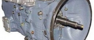
Since 1971, the first T 150 tractor was produced in Kharkov, which is currently considered one of the veterans among this class of transport. Now this unit is widespread in almost all countries of the post-Soviet space. The tractor is powered by a YaM3-236 diesel engine, the power of which is about 170 horsepower. The T 150 tractor gearbox is also produced at this plant - it is practically inseparable from the engine and is mounted on the frame. Next, we will consider the basic principles of operation of the T 150K and T 150 tractor gearbox, differences and features.
What is a gearbox for the T 150 tractor?
The gearbox is a manual gearbox with hydraulic control. With this design, the gearbox on the T 150 tractor can be switched on the fly without interrupting engine power. In addition, the advantage of this design is an increase in vehicle performance and fuel economy, which is very important when calculating the cost of equipment. It is much easier for the driver to drive such vehicles. Also in the gearbox there is an element called a creeper, which allows movement at low speeds. This is a very useful property for industrial work, because... as the speed decreases, the thrust of the unit increases.
Owner reviews
I took the T-150K tractor second-hand at a good discount due to a broken SMD engine block. The technical center suggested installing a German Deutz diesel engine identical in power. I had to invest additional money, but the replacement turned out to be complete in all respects. Traction has increased by at least 20-25%, although I don’t know how this will affect the durability of the gearbox and transmission as a whole. Semyon Nikolaevich
After 8 months of working at MTZ-82, the management of the agricultural company decided to transfer me to a completely overhauled T-150K tractor. The difference is significant, although during the running-in period the gearbox gearbox had to be replaced, and there were minor problems with the power steering. The car is excellent in terms of traction characteristics and maneuverability, I recommend it to everyone. Volodya
Switching ranges
The designers fit 4 modes into the device:
- slow mode;
- worker;
- transport;
- reverse.
Each of the intervals in the gearbox of the T 150 tractor contains 4 gears and 4 clutches located on the second shaft. To change mode, the vehicle must stop. After this, pay attention to the gears that need to be engaged. Due to this, the rotation of the shafts will start. Below is a diagram of the T 150 tractor gear shift. The speed is adjusted using two levers: the left one is responsible for the modes, and the right lever is for changing gears.
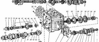
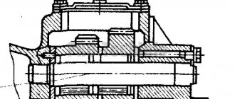
Design and structure
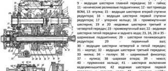
The T 150 tractor gearbox is not similar to other vehicle models in that it has two brake shafts (in other models it is usually one). Each of the shafts is designed for movers on the left and right. With this design it is possible to change the speed and traction of the tractor. In addition, this allows the equipment to be rotated in any radius. When the unit moves in a straight line, the shafts operate at the same frequency. If it is necessary to make a turn, then one slows down or their frequency diverges.
On the surface of the T 150 tractor gearbox housing there are mechanisms that allow you to switch rows and turn on shafts with pumps. Here the axle is inserted onto which the lever for the box is put. Through traction force it is connected to the brake pedal. A detailed diagram of the T 150 tractor gearbox, element designations are located below in the article.
Dimensions, weight
Tractor t 150k technical specifications
| Length with towbar, mm | 5735±50 |
| Height, mm | 3165±40 |
| Width, mm | 2340±30 or 2520±30 |
| Base, mm | 2860 |
| Track, mm | 1680±40 or 1860±40 |
| Minimum turning radius, m | 6,5 |
| Ground clearance, mm | 400 |
| Tractor weight, tons | 8,1-8,75 |
Differences between gearbox models 150 and 150K
Despite the similarity in the design of the two units, the T150 gearbox has several differences from the T 150K. The main advantage is that you do not need to stop the vehicle to change gears. All thanks to the specific design of the box, which was described above. In the mechanism, the hydraulic clutch of the transmission is first connected, and then the clutch that controls the previous gear is disconnected. Thus, in a short time interval, two clutches operate simultaneously, due to which the switching is inseparable. The only thing you have to stop the unit for is to change the mode.
Another significant change that the gearbox has undergone: the presence of a creeper. In this case, the input shaft has an intermediate connection with the clutch mechanism. Typically, special equipment includes soft connection structures - most often these are rubber gaskets. However, the design of the T 150 gearboxes contains metal components, so the connections in the device are rigid.
Switching gearboxes of different tractor models
In general, the designs of models of different years of production are similar to each other. But there are also a number of changes that affect how you shift gears. If the owner is faced with a tractor manufactured before 1983, then he is dealing with an old model. In new tractor models, the gearbox is slightly different: the thrust is increased to 40 thousand Newtons, it has reinforced bearings, as well as special teeth. In new versions of the gearbox, a high-speed gearbox is installed.
Modifications
The 150 series tractor today has four modifications, all of which belong to the T-150K model.
At its base, an army version of the T-154 was produced, with the help of which they carry out engineering and construction work and tow non-self-propelled artillery installations.
Differences from the base model include the presence of a tow hook instead of a pendulum linkage, the possibility of pre-heating the engine, and a higher travel speed. In addition, the rear half-frame is made elongated and carries a cargo body.
The modified T-156 machine is equipped with a bucket and is capable of performing loading work, and the LT-157 is a skidder and is used in logging.
The machines of the Kharkov plant were the basis for the development by the Rybinsk plant of a single-axle tractor operating as part of self-propelled scrapers and asphalt rollers. Its rear frame was replaced with the frame of the corresponding vehicle and the hinge between the half-frames was modified.
Features of changing gearbox oil
Units of this type require regular oil changes, but not every owner understands how to choose and fill the substance correctly. The condition of the tractor and its service life depend on how often the replacement is carried out. Experts recommend using only special consumables and technical fluids that can provide operating conditions for the transmission. If it is not possible to choose specific technical fluids, then it is better to consult a specialist.
To determine the amount of oil in the box, regular checking of the indicator is necessary. You need to check the oil level periodically. Just look through the viewing window. It is installed on the transmission housing.
Regarding pouring oil into the gearbox, experts recommend changing it at least twice a year, even if there is still enough of it in the gearbox. It is better to do this in the off-season or when the owner intends to change the filters.
It is necessary to take into account the fact that it is necessary to add oil to the T 150 only when the engine is running. It is better to start the vehicle in advance - you need to give the engine at least 5 minutes of time after starting. The level is also monitored through the viewing window. Another difference between the two tractor models is that the engine must be stopped when adding oil to the T 150K.
Experts advise choosing the same oil for both the gearbox and the gearbox with a hydraulic system. The main selection criterion is temperature conditions. For example, under conditions below 25 degrees, it is recommended to dilute the gearbox oil with windy oil in a ratio of 1:2. If the owner does not have the opportunity to add winter fluid, then there is an alternative solution: 1 part of windy AC is added to 2 parts of summer technical fluid. This method is best used only as a last resort - special oils will better protect the structure from premature failure.
Transmission pressure is another indicator that needs to be constantly monitored. This can be done using an installed pressure gauge, which is located in the working area (panel).
Engine SMD-60
All modifications of tractors are equipped with diesel six-cylinder four-stroke supercharged SMD-60 engines with a 150-horsepower rated power. They were developed specifically for these machines, have a V-shaped arrangement of cylinders and liquid cooling.
The engine start is double: from the cab, using an electric starter, a starting gasoline engine is started, which serves to spin up the main unit. The T150 tractor is equipped with a three-stage system of highly efficient air purification supplied to the fuel system. It consists of an inertial oil (fine filter), two-stage (has ejection removal of settling dust) and a dry cyclone filter.
To make it easier to start the engine at temperatures below -5ºС, a pre-start heater PZHB-300 is provided.
Transmission setup
To avoid breakdowns of the T 150 gearbox, it is advised to configure the unit and adjust it correctly. To adjust the mechanism, you must adhere to the following instructions:
- The driver releases the clutch;
- The transmission mechanism is installed in the correct position;
- Screw the plug until the hole is on the opposite side of the finger;
- Connect the locking roller lever and the clutch.
If the equipment is configured correctly, it will be possible to change speeds when the clutch is engaged. It is allowed to engage the gear mechanism only when the mechanism is released. If everything worked out, then the last step is to tighten the nut and pin the pin.
Gearbox breakdowns and problems. Elimination methods
The gearbox is a fairly simple design that has proven its reliability in practice. However, there is always the possibility of a breakdown, which only a highly qualified specialist can handle. At the same time, the technician must have experience working with such a mechanism, otherwise the repair will be performed poorly and the problem will not go away. Most often, the tractor owner has to face the following problems:
- It is difficult to change gears - most likely, the problem lies in the distributor spool. In this situation, it is recommended to rinse the part and its location.
- It is difficult to engage the rows, and the clutch pedal does not return to its original state. The problem is the length of the rod - it needs to be adjusted.
- When changing gear, the speed decreases. The failure lies in the distributor. It is necessary to check the consumables - the rings or cover may be worn out, or the gasket may be torn.
- Gear shifting is accompanied by jerks. There may be several reasons for the breakdown: the transfer valves are stuck or the battery is jammed (you need to wash it).
- Passes are difficult to record. The clamp spring may weaken or the roller may come off. In the first case, you need to install the clamp and tighten the spring.
- During gears the pressure decreases. It's a bypass valve issue. In this case, you need to wash it and the gearbox filter. If the pressure increases, then the problem is also in the bypass valve (or it may be in the distribution bypass valve).
- Incorrect pressure reading on the pressure gauge. In this case, the throttle hole is clogged or there is a problem in the pressure gauge (then it must be replaced).
A poronite sealing gasket is placed between the pump and the lower cover of the transfer case. The pump is connected to the transmission hydraulic system using a flange clamp, aligning the suction and discharge holes in the rear cover of the pump with the corresponding channels in the lower cover of the transfer case.
The pump consists of a housing, a rear cover with discharge and suction holes, a front cover, drive and driven gears.
The drive gear is integral with the roller having flats. The drive gear with the shaft rotates in bronze bushings pressed into the covers.
The driven gear rotates on a bronze bushing relative to an axis fixedly installed in the pump.
Rice. 1. Adjusting the gearbox hydraulic system pump drive: 1 - drive shaft: 2 - bushing; 3 - simple body; A and B - shims.
The pump is secured with four bolts in addition to those that attach it to the bottom cover. Two pins fix the relative positions of the pump parts during assembly. The pump is driven by the engine through a rear linkage hydraulic pump drive shaft and a pair of bevel gears. Pump capacity 25 cm3/revolution, operating pressure 9.0-9.5 kgf/cm2.
Suction hole A in the bottom cover is connected to hole B, which is located under the suction filter. The suction filter is a stamped frame covered with brass mesh. The suction filter flange is bolted to the plane of the bottom cover, covering hole B. From the discharge cavity of the pump, oil under pressure is supplied to the horizontal hole B of the bottom cover, at the outlet of which a thread is cut to connect the discharge pipeline fittings.
The discharge line filter, which serves for fine oil purification, is installed on the top cover of the gearbox. The filter is placed in a housing, which is a pipe with a shaped bottom, which is connected to the plate. Above the stove there is a cast lid with channels for draining filtered oil. Between the cover 6 and the plate, as well as the plate and the upper plane of the gearbox cover, sealing gaskets are installed. The cover and plate with the housing are attached to the gearbox cover with bolts.
The filter is connected to the hydraulic system using a flange clamp when the holes L and B are aligned with the holes in the gearbox cover.
The housing contains the filter itself, consisting of lenticular mesh filter elements B, put on a perforated pipe and compressed by a spring through a tie rod. The spring is clamped by a shaped nut and a locknut, which are screwed onto the tie rod. The spring is pulled until the washer is flush with the end of the piston.
A piston with a rubber sealing ring installed in the cover well separates the filtered and unfiltered oil cavities. The set of filter elements includes a ball valve, adjusted to an operating pressure of 3-3.5 kgf/cm2. If the filter is excessively dirty, the valve allows unfiltered oil into the system, preventing destruction of the filter elements.
The safety valve is installed in the housing. A cap is screwed onto the body, to the socket of which a ball, which serves as a valve, is pressed by a spring.
Rice. 2. Pump NMSh-25 and suction filter: 1 — bottom cover of the transfer case; 2— body; 3 — front cover; 4— axis; 5 - suction filter; 6 - pin; 7 — back cover; 8—bronze bushing; 9—drive gear; 10— driven gear; A, B, C - channels.
The pump is secured with four bolts in addition to those that attach it to the bottom cover. Two pins 6 fix the relative position of the pump parts during assembly. The pump is driven by the engine through a rear linkage hydraulic pump drive shaft and a pair of bevel gears. Pump capacity 25 cm3/revolution, operating pressure 9.0-9.5 kgf/cm2.
Suction hole A in the bottom cover is connected to hole B, which is located under the suction filter. The suction filter is a stamped frame covered with brass mesh. The suction filter flange is bolted to the plane of the bottom cover, covering hole B. From the discharge cavity of the pump, oil under pressure is supplied to the horizontal hole B of the bottom cover, at the outlet of which a thread is cut to connect the discharge pipeline fittings.
The discharge line filter, which serves for fine oil purification, is installed on the top cover of the gearbox. The filter is placed in a housing, which is a pipe with a shaped bottom, which is connected to the plate. Above the stove there is a cast lid with channels for draining filtered oil. Between the cover 6 and the plate, as well as the plate and the upper plane of the gearbox cover, sealing gaskets are installed. The cover and plate with the housing are attached to the gearbox cover with bolts.
The spring serves to push out the tension set of filter elements during disassembly.
Unfiltered oil from the pump is supplied through channel A into the cavity of the filter housing, pressed through the filter elements, filtered at the same time and enters the cavity of the perforated pipe. Then, through the top cover, through channels B, it is further supplied to the bypass valve, hydraulic movable couplings and other elements of the transmission hydraulic system.
Reliable operation of all hydraulic components depends primarily on the purity of the working fluid in the system. Therefore, during operation, it is necessary to strictly observe the timing of filter washing and monitor the integrity of the filter elements.
The hydraulic accumulator is attached to the flange of the right wall of the gearbox housing with six bolts. The hydraulic accumulator maintains pressure in the clutch of the gear being disengaged at the moment of gear shifting.
The hydraulic accumulator consists of a housing and a cover. Inside the housing is a piston sealed with a rubber ring and two protective washers. A sealing gasket 9 is clamped between the cover and the body. In a discharged hydraulic accumulator, the piston is pressed against the cover by the force of the springs. The springs rest against a sleeve closed in the body. The above-piston space of the accumulator communicates with the transmission hydraulic system through hole A in the housing. The hydraulic accumulator is connected to the hydraulic system using a flange clamp to the box body, and then through a pipeline connecting the hole in the body on the side wall with the hole in the body communicating with the hydraulic distributor. A sealing gasket is clamped between the accumulator body and the gearbox housing flange.
The pre-compressed springs of the hydraulic accumulator develop 600 kgf. This force in an uninstalled hydraulic accumulator is perceived by three bolts. Under the influence of working fluid supplied under pressure through hole A, the piston moves, overcoming the forces of the springs. In this case, the hydraulic accumulator is filled with working fluid, i.e. it is charging.
The bypass valve maintains a constant operating pressure in the system (9.0+0'5 kgf/cm2) regardless of the number of revolutions per minute developed by the engine.
Rice. 4. Bypass valve: 1 - body; 2 - sleeve; 3—valve; 4. 6 — washer; 5, 13—spring; 7 - adjusting screw; 8 - nut; 9— sealing ring; 10—cap; 11 - ball; 12—socket; 14, 17 — plug; 15 — adjusting gaskets; 16 — saddle; 18 - fitting.
The pipeline is connected to the radiator and tank through a fitting screwed into the valve body. The bypass and safety valves are adjusted and sealed at the factory. The plugs are sealed with rubber gaskets and secured with wire passed through the drillings in their heads and tied to the eye of the body.
The distributor, controlled by a lever from the tractor cabin, makes it possible to direct the working fluid into the working cylinder of one of the four hydraulic clutches to compress the disk pack.
The distributor is placed on the front shank of the secondary shaft and secured with six bolts to the front wall of the transmission housing. There is a sealing gasket between the distributor and gearbox housings. The distributor is connected to the gearbox hydraulic system using a flange clamp when the holes and channels in the adjacent surfaces of the distributor and the gearbox housing are aligned.
A hardened steel sleeve with four rows of holes is pressed into the distributor body. The holes in each and the end of the secondary shaft.
Rice. 5. Distributor: 1 - spool; 2 - cover; 3— sleeve; 4 - body.
Rice. 6. Distributor
Rice. 7. Gearbox pipelines: 1 - pipeline from the pump to the filter and bypass valve; 2 - pipeline from the bypass valve to the distributor; 3— pipeline for supplying lubricating oil to the distributor
rows extend into the annular channels of the liner and at the same time coincide with the annular channels on the shank of the secondary shaft. The sealing rings of the secondary shaft shank are in contact with the inner surface of the liner. The annular channels of the liner are connected by drilling to the well in which the spool is located. The spool has distribution grooves A and radial throttle holes B connected to the axial channel. At the end of the spool there is a gear ring that engages with the teeth of the sector. The sector is a part manufactured integrally with a shank and a comb with four cavities.
The sector shank rotates in a bushing in the side cover and is sealed with an oil seal and boot. A lever connected to the control rod is secured to the sector shank using a segment key and a tightening bolt.
The spool and sector are assembled according to the marks marked on the corresponding teeth and cavities. The spool paired with the body is a precision pair; disassembling them is unacceptable. A latch is installed in the side cover, the roller of which fits into the depressions of the sector comb. The latch is pressed by a spring, the force of which is adjusted with a screw. The screw is locked with a locknut. Three wells located in the upper part of the side cover are connected to each other by channels and plugged on both sides with plugs. A movable transfer valve is installed inside each well. The purpose of the overflow valve system is to automatically execute the gear shift program under load without stopping the tractor. The side cover is attached to the distributor body with six bolts, and to the transmission hydraulic system with a flange clamp when aligning the holes and channels. A gasket is installed between the distributor body and the cover. There is a threaded hole on the side cover to which the oil line fitting to the pressure gauge is connected. This hole is connected to a channel connected to the hydraulic accumulator of the central transfer valve.
Rice. 8. Pipelines, tank, radiator: 1 - tank; 2 - valves; 3 - pipe; 4, 5, 7, " - pipeline; 6 - radiator; 8 - filler filter.
Rice. 9. Radiator: 1, 3 — oil sump; 2—tube.
Transmission hydraulic tank. The amount of working fluid—oil—in the gearbox is not enough to maintain normal thermal conditions. To increase the amount of oil in the hydraulic system, a cylindrical tank with a capacity of 22 liters is installed in the front beam of the tractor frame. The tank is connected by a pipeline to the gearbox. The transmission hydraulic system radiator is connected to the tank through a pipe. A ball valve is installed in the pipe, designed to automatically turn off the radiator when the oil is not warmed up enough and its viscosity is increased. The socket and valve ball are located in such a way that oil cannot leave the tank, but can only enter the tank.
A mesh filler filter is connected to the tank by a pipeline, mounted on the right rack of the engine water radiator.
Oil is filled into the gearbox hydraulic system through a filter by gravity or to reduce time under pressure at the intervals specified in the “Maintenance” section.
The radiator serves to maintain normal temperature conditions of the hydraulic system of the gearbox. It is located in front of the engine oil cooler and is mounted on its side struts. A single-flow tubular radiator consists of two oil collectors (Fig. 92), which are connected by flat-oval steel tubes soldered to them. To increase rigidity in the middle part of the radiator, the tubes are connected to each other by a diaphragm. The working fluid is supplied and lowered to the radiator oil collectors through pipes welded to them. The gearbox is connected to the radiator through pipelines, and the radiator is connected to the tank through pipelines. All other pipelines are connected through sections of flexible hoses covered with clamps on the pipelines.
Operation of the hydraulic system. The hydraulic clutches of the secondary shaft are activated under the influence of oil pumped into the working cylinders (booster).
The piston, moving under oil pressure, compresses the clutch disk pack, which at the same time begins to transmit torque from the gear along the secondary shaft. When the cavity under the piston communicates with the drain, the piston returns to its original position under the action of springs. The remaining oil is thrown out from the rotating clutch cylinder through the valves, the balls of which, under the influence of centrifugal forces, move away from the seats and open the holes.
Depending on which booster the oil is supplied to, one or another gear of the row is engaged.
Gears are switched by a hydraulic distributor.
On the T-150K tractor, the tractor driver changes gears on the move under load, without stopping the tractor. This is achieved by the automatic operation of the feed clutch hydraulic system. Figure 93 shows a diagram of the transmission hydraulic system. The transmission hydraulic system runs on diesel oil.
The oil from the transfer case pan is sucked up by the pump, passing through a mesh suction filter. Large particles are captured by the filter and do not penetrate the pump; small steel and cast iron particles are attracted by the magnet and settle on it.
The oil pumped by the pump is forced through the discharge filter, where fine cleaning occurs, after which it flows to the bypass valve, distributor and then to the radiator and tank. From the distributor, the oil enters the annular channel of the liner, corresponding to the gear being engaged, against which the distribution groove of the rotating spool is installed. Next, the oil, through the annular groove and channels of the secondary shaft, enters the booster of the corresponding hydraulic clutch. At the beginning of the action, the piston of the hydraulic clutch moves as the booster is filled, and then takes a position corresponding to the compressed pack of friction discs. The booster fills in approximately 0.3 s at rated engine speed. Next, only enough oil is supplied to the booster to replenish the leaks in it. After filling the gear booster, the hydraulic accumulator 8 is charged, which is connected in the hydraulic distributor in parallel to the gear booster using a system of channels and pipelines.
When the gear booster is filled with oil pressure, the transfer valves are moved to a position in which the hydraulic accumulator 8 is connected to the gear booster. After filling the booster and charging the hydraulic accumulator, the oil, constantly pumped by the pump, is purged through a bypass valve adjusted to 9.0+0.5 kgf/cm2. Since the pump's performance is many times greater than the volume of leaks in the circuit, the hydraulic system is maintained at a pressure determined by the bypass valve. The etched oil from the bypass valve is sent through a pipeline to the radiator and to the hydraulic system tank. Part of the etched oil is branched off and sent through a pipeline to the end of the secondary shaft, then through a metering throttle and central lubrication channels to water and lubricate the discs and bearings of hydraulic clutches. From the pipeline, the etched oil is sent to the radiator, cools, passes through it and enters the tank. Until the oil warms up and its viscosity increases, it bypasses the radiator and passes through the valve directly into the tank.
Rice. 10. Hydraulic diagram of the gearbox
At the moment when the pressure in the booster and the channels of the 2nd gear clutch exceeds the pressure in the hydraulic accumulator, booster and the channels of the 1st gear clutch, which usually occurs at 4.4-5 kgf/cm2, the transfer valves, under the influence of the pressure difference, will move to a position such as shown in Figure 94.6. The hydraulic accumulator will be cut off from the booster and channels of 1st gear and connected to the booster and channels of 2nd gear. The hydraulic clutch of the first gear, the booster of which is no longer fed by the hydraulic accumulator, will stop transmitting torque. Then the pressure in the 2nd gear booster will continue to increase, and the accumulator will restore its charge, at the same time, the 1st gear booster will be completely emptied through the throttle hole, and the remaining oil will be thrown out through the centrifugal valve.
The process of engaging 2nd gear will be completed when the hydraulic accumulator is fully charged and the pressure in the system increases to 9.5 kgf/cm2.
The time when both clutches simultaneously transmit partial torque is tenths of a second. The entire process of switching on the fly from one gear to another takes place in 0.28-0.40 s.
Since the pressure gauge is connected to the accumulator cavity, it shows the pressure in the booster of the previously engaged gear until the corresponding transfer valve is reset, and then the pressure in the booster of the newly engaged gear.
On the pressure gauge you can see during the gear shift process, first a pressure drop to 4-4.5 kgf/cm2, which corresponds to the process in the booster of a previously engaged gear, and then an increase in pressure to 7.0-7.5 kgf/cm2, a short delay at this magnitude, and then a quick jump to 9.0-9.5 kgf/cm2. The stage of increasing pressure corresponds to charging the battery after the booster of the newly engaged gear is completely filled, and the jump corresponds to the moment the bypass valve fully enters the process.
Maintenance of the gearbox and its hydraulic system, adjustment
Gearbox maintenance includes timely refueling, topping up and changing oil in accordance with the lubrication table, cleaning and rinsing filters and breather, monitoring the condition of the seals and the pressure in the transmission hydraulic system.
It is necessary to periodically clean the outside of the gearbox from dust and dirt, monitor the fastening of the units, and regularly tighten the threaded connections.
Fill the hydraulic system of the gearbox with clean, well-settled oil and within the time limits specified in the lubrication table.
When washing the intake filter, foreign particles should be completely removed from the mesh, and when washing, the discharge filters should be disassembled, each filter element should be thoroughly rinsed and cleaned individually, and all filter parts should be blown with compressed air. After washing, assemble the filter and install it in place.
Periodically, but at least every 240 hours, it is necessary to unscrew and wash the breather.
Rice. 11. Diagram of operation of transfer valves: 1 - throttle holes: 2 - valve of 1st and 3rd gears; 3— central valve; 4 - battery; 5 - valve for II and IV gears.
Attention!
Due to the fact that on the tractor T-150K. A hydraulic gearbox with on-the-fly shifting is used; during operation, it is necessary to constantly monitor the pressure in the hydraulic transmission system according to the readings of the pressure gauge installed in the cabin. In a working hydraulic system of the gearbox, the pressure depends on engine speed to a small extent (a decrease of no more than 1 kgf/cm2 when moving from 2100 rpm to idle speed).
If there is a significant increase or decrease in pressure on one or part of the gears, the tractor must be stopped, the cause must be identified and the defect eliminated. The nominal pressure at steady state (2100 rpm) of the engine is 9.0+0.5 kgf/cm2.
It is strictly forbidden to work at a pressure below 7 kgf/cm2.
Features of adjustment, assembly and disassembly of the gearbox and its hydraulic system
Adjusting the pump drive. In case of replacing bevel gears of the pump drive, it is necessary: a) by selecting gaskets A, set the size to 42.5 ± 0.15 mm; b) by selecting gaskets B (when the shaft assembly with gears rests through the bushing into the ring of the spacer housing 3), set the gap in the teeth of the bevel pair to 0.24-0.4 mm.
Adjustment of the locking mechanism for switching rows of the speed reducer and reverse gear is made by changing the length of the rod connecting: the locking roller lever and the clutch control lever. To do this, you must: a) disconnect the rod from the locking roller lever; b) fully depress the clutch pedal; c) install the locking roller so that the symmetry axis of the lever coincides with the edge of the pointer, and adjust the length of the rod by screwing or screwing the fork. Connect the fork to the lever d) check the adjustment, then tighten the pin and tighten the lock nut.
The gear shift drive is adjusted by changing the rod length.
To adjust, it is necessary: a) set the distributor lever horizontally (parallel to the longitudinal axis of the gearbox) to the fixed position of the spool; b) when screwing or unscrewing the fork, adjust the length of the rod so that with this position of the lever, the number on the gear selector scale is opposite the pointer arrow.
Bypass valve adjustment. The bypass valve is adjusted at the factory to a pressure of 9.0+0.5 atm and sealed. It can be readjusted only if really necessary, after first making sure that the pressure gauge reading is correct. Before adjustment, it is necessary to warm up the oil in the gearbox hydraulic system to a temperature of at least 70 °C.
When adjusting, you must: a) unscrew the cap; b) unscrew the locknut; c) with the engine operating at 2100 rpm, rotate the screw and adjust the pressure to 9.0±0.5 kgf/cm2. Next, all operations are carried out in reverse order.
It is necessary to ensure that the rubber O-rings are in place.
Adjustment of the distributor lock should be carried out in case of excessively large and small force on the gear shift lever in the cab, as well as loss of “click” on the lever when changing gears.
Before making adjustments, make sure there are no jams in the rod system.
To adjust, you must: a) unscrew the cap and partially unscrew the lock nut; b) use a screw to adjust the action of the clamp: if the cut-off is weak, screw in the screw, if it is too tight, unscrew the screw; c) ensure normal operation of the latch, lock screw 6 with a lock nut and, screwing on the cap, protect it from unscrewing with wire.
Make sure there are aluminum or red-copper sealing washers under the locknut and cap.
The hydraulic accumulator can only be disassembled by removing it from the gearbox and unscrewing the six mounting bolts. After this, the hydraulic accumulator remains assembled, since the force of its pre-compressed springs, exceeding 600 kts, is perceived by three bolts, the heads of which are painted red. To avoid accidents, they can only be unscrewed by squeezing the hydraulic accumulator under pressure or inserting at least three auxiliary M10 safety bolts with a length of at least 110 mm into the free mounting holes, with the nuts tightened until they stop. The threads on the safety bolts should be no further than 30 mm from the head. After unscrewing the three bolts, you should gradually loosen the hydraulic accumulator by releasing the press or gradually and alternately unscrewing the nuts on the safety bolts. Assembly is carried out in reverse order.
Disassembly and assembly of the distributor. The hydraulic distributor could only be removed on the gearbox; removed from the tractor. To remove the distributor, it is necessary to unscrew the seven bolts securing the distributor to the front plane of the gearbox housing. When installing the hydraulic distributor on the gearbox, it is necessary that the pin fits into the groove of the front bearing of the secondary shaft.
After the final tightening of the seven mounting bolts, you need to remove the distributor cap (see Fig. 88), unscrewing the four bolts, and use a feeler gauge to check the uniformity of the gap between the cylindrical surface of the secondary shaft shank and the distributor sleeve. Dipstick 0.15
must go around. The check should be carried out with the output shaft fully covered.
If the probe does not pass in any area, you need to partially loosen the bolts securing the distributor to the box housing and tighten them in a different sequence. If this measure does not lead to the required uniformity of the gap, then you should unscrew the bolt from the rear end of the secondary shaft, move the sleeve and gear 29 by 90°, then retighten the secondary shaft and re-check the uniformity of the gap. At the end of the check, install the distributor cap on the four bolts.
When installing the side cover of the distributor, it is necessary to align the parts so that the mark on the sector tooth is positioned exactly opposite the mark on the corresponding cavity of the spool crown.
The spool and body are a precision pair, so disassembling them is not allowed during disassembly.
When assembling the secondary shaft kit, it is convenient to place the box vertically, with the rear end up. Install spacer rings, gears and drums in a vertical stack in the required sequence and, feeding the secondary shaft from above, pass it through the splines of the package parts and the front bearing; After this, install the rear bearing. To facilitate the alignment of the secondary shaft with the splines of the package parts, you should align the splines of the bushings in the same plane with the splines of the drums, using a spatula-device, which can be easily made according to the sketch in Figure 15.
Rice. 15. Device for assembling hydraulic clutches.
When assembling secondary shafts and hydraulic clutches, it is necessary to align the oil lines of the corresponding gears. To do this, the hydraulic clutches and the secondary shaft must be positioned as shown in Figure 77.
One arrow stamped on the rear clutch drum and two arrows stamped on the front clutch drum should be directed along the tractor and located at the top, and the mark stamped on the front end of the secondary shaft should be in the same plane with them and facing upwards.
When tightening the secondary shaft kit, first tighten the nut until it stops and lock it with the flange plate, then tighten the bolt.
In clutches that have an even number of pairs of disks, the driven disks with springs are installed through one and the location of their springs is indifferent, since they cannot meet.
On couplings with an odd number of disks, the last and penultimate driven disks with springs (counting from the piston) are installed side by side (not counting the driven disk located between them), and therefore their splined protrusions with springs must be turned relative to each other by one spline.
The spring package (see Fig. 76) is compressed under a press or a special screw device before installing the ring. When assembling, you need to pay attention to the integrity of the ring lock and install the rubber sealing ring without twisting it.