The KAMAZ steering mechanism is equipped with a hydraulic booster (GUR), which is designed to reduce the effort that the driver has to apply to rotate the steering wheel. Power steering also plays the role of a damper, which softens vibration and shock from various objects on a bad road (cobblestones, holes, uneven surfaces, etc.) and protects the entire KAMAZ steering system from premature wear and destruction. Power steering also allows you to control the movement of the car, including a loaded one, in the event of a sudden rupture of one of the front tires.
Steering system components
The KAMAZ steering system of modifications 5320 and 4310, as well as some similar models, includes the following components and mechanisms:
Steering control of KamAZ vehicles
- Steering wheel.
- Steering column.
- Cardan shaft (cardan).
- Cooling system radiator.
- Power steering control valve.
- Angular gearbox.
- Power steering coupled with the steering mechanism.
- Longitudinal thrust.
- Bipod.
- Low pressure pipeline and high pressure pipeline.
- Power steering pump.
- Liquid storage container.
If the hydraulic booster fails, the ability to control the KAMAZ and continue driving is preserved thanks to the presence of a check valve, which will ensure the connection of the high and low pressure lines. At the same time, the wear rate of parts increases many times over, and the probability of their failure increases in proportion to it.
If the power steering breaks down, it is unacceptable to continue operating the machine. The check valve is intended only to reach a service center or repair base.
How to adjust the steering wheel height and reach
A correctly adjusted steering wheel makes any trip more comfortable for the driver (the arms and back do not get tired from being in one position for a long time). It also improves traffic safety. A correctly positioned steering wheel does not obscure the instrument panel and allows full access to the readings of the main instruments.
Types and types of adjustment
Steering wheel adjustment is considered a basic option for every modern car. It is carried out manually or using an electric drive. Among the varieties of types and types of adjustment, several main ones can be distinguished.
Lobdell system design
The basis of this system is a ratchet mechanism that serves as a place for attaching the steering wheel. This design is capable of changing the position of the steering wheel without moving the steering column itself.
The main disadvantage of the Lobdell system is the small range of changes (you can only choose from 7 main provisions). In addition, the steering wheel is not able to change the angle of inclination, and this significantly reduces the convenience of driving the vehicle. However, it was precisely this system that was first installed on a Cadillac car many years ago.
Telescopic steering wheel
For the first time, such a system was proposed for installation at the General Motors plant. Its essence lies in the fact that the steering wheel is adjustable in a three-inch range, but the direction of the steering wheel is selected with greater accuracy than in the previous system. This adjustment technique is still used today, for example, in some Honda car models.
Adjustable steering column
In this system, the range over which the steering wheel can be moved is quite small, but it is possible to adjust its tilt. This method was modernized by Ford car developers, who proposed moving the steering wheel back every time the driver got in and out. Then this system was equipped with electric motors and mechanical locks, which allowed the system to remember and reproduce the steering parameters specified by the owner.
Electronics
New prestigious cars are equipped with an automated system that, under electronic control, is able to independently adjust the comfortable position of the steering wheel. The driver just needs to choose a position that is comfortable for him in terms of inclination, height and distance, and then make changes to the virtual memory of the on-board computer.
The system uses sensors to read the position of the ignition key and door handle. According to this information, when the ignition is turned off, the engine starts, which raises the steering wheel so that the driver can get out or sit down without touching the steering wheel with his feet. After it reaches the required position, the steering wheel returns to its original state.
Steering column structure of KAMAZ models 5320, 4310, 55111
The steering column of KAMAZ vehicles of these modifications is a rather complex complex device. It includes the following nodes:
KAMAZ steering column
- steering shaft;
- locking and expansion ring;
- two ball bearings;
- a pipe that plays the role of a body;
- lock washer;
- nut for adjusting bearings.
The column has two attachment points: in the upper part - to a bracket hidden under the cockpit dashboard, in the lower part - to a flange on the cab floor. It is connected to the other components of the control system using a cardan and an angular gearbox. The drive gear of the gearbox is an integral part of the cardan shaft and is mounted on bearings in the housing.
The gear ratio of the mechanism is 20.
How to adjust steering wheel height and reach
Almost every car has the ability to adjust the steering wheel. This also applies to budget models. Unfortunately, few people know how to adjust the steering wheel. And that's bad. After all, correct installation allows you to increase the comfort of the trip and reduce the load on your arms and spine. When the question is how to adjust the steering wheel, it is worth noting that there are two types of adjustment. The reach and angle of inclination determine how comfortable it will be to drive the machine. This applies to people of different heights. The basic setting is designed for drivers of average height. Driving theory does not always cover this topic, but you can always talk to your instructor about this.
Why do you need to adjust the steering wheel height?
To make your trip comfortable and safe, you need to carefully approach the issue of how to properly install the steering wheel. This will ensure easy access to the dashboard. The driver has the opportunity to monitor instrument readings. If installed incorrectly, the load on the hands and the whole body increases.
Steering shaft cardan device
The cardan of KAMAZ 5320, 4310 and similar modifications is supported on hinges mounted on needle bearings. These bearings are maintenance-free; the required amount of special type grease is added to them at the factory. Bearings do not need to be replaced with grease throughout their entire service life.
The nature of the connection—sliding type—provides the ability to tilt the driver's cabin to access the mechanisms hidden underneath.
KAMAZ steering shaft cardan
In addition to bearings, the KAMAZ driveshaft consists of:
- forks;
- thrust and sealing rings;
- O-ring cages;
- crosses;
- second fork with splined rod;
- third fork with splined bushing.
The splines are coated with a layer of special lubricant, which is also placed in the bushing.
The cardan forks are attached to the bevel gear (its drive gear) using a system of wedges. The wedges are held in place by cotter nuts.
Angular gear design
The angular gearbox is a technically complex unit that transmits the rotation of the shaft (in turn, rotated by the steering wheel) to the screw of the KAMAZ steering mechanism. It consists of the following elements:
- housings with lid;
- driving and driven gears;
- drive gear shaft coupled to the cardan;
- ball bearings with fastening nut;
- O-rings;
- thrust ring, washer and thrust cap;
- adjusting shims;
- cuffs;
- protective cover.
Ball bearings are held on the drive gear shaft by pressing. To avoid accidental displacement, they are secured with a nut, the collar of which is pressed into a groove on the shaft. A retaining ring and thrust cap also serve to hold the bearings.
The shims are designed to regulate the engagement of the drive and driven gears. The gear teeth are spiral.
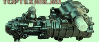
Steering mechanism of KAMAZ modifications 5320, 4310, 55111
The KAMAZ steering mechanism has a built-in hydraulic booster. This combined unit is attached to a bracket on the car frame in the area of the front left spring. It consists of:
- covers - front, rear and side;
- power steering control valve;
- locking, sealing and spacer rings;
- floating bushing;
- set screw;
- bipod shaft;
- bypass valve;
- protective cap;
- crankcase;
- piston-racks;
- magnetic drain plug;
- screw;
- balls and ball nuts;
- gutters along which the balls move;
- thrust bearing;
- thrust, adjusting and spring washers;
- adjusting screw with lock nut.
The main structural element is the screw, to which the rotation of the driven gear from the bevel gear is transmitted. As the screw rotates, it transmits rotation to the control valve spool. In this case, turning the spool clockwise or counterclockwise changes the degree of communication of the cylinder cavity with the fluid injection and drain lines.
When the spool is turned clockwise, the liquid enters one part of the cavity and is pumped out from the other; when turned counterclockwise, the opposite is true. The movement of fluid creates additional force, which makes it easier to control the machine. This is the principle of operation of the hydraulic booster.
The purpose of the adjusting screw is to change the gap in the engagement of the bipod shaft and the piston-rack. The screw is located in the side cover.
_______________________________________________________________________________
Steering of Kamaz vehicles and its components
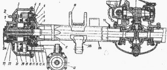
The Kamaz steering (Fig. 1) is equipped with a hydraulic booster 7, combined in one unit with a steering mechanism, a hydraulic booster control valve 5 and an angular gearbox 6.
Fig.1. Steering Kamaz 1 - steering wheel; 2 - column; 3 — cardan shaft; 4 - radiator; 5 — power steering control valve; 6 — angular gearbox; 7 - hydraulic booster with steering mechanism; 8 — longitudinal thrust; 9 — bipod; 10 - low pressure pipeline; 11 - high pressure pipeline; 12 — power steering pump; 13 — hydraulic system reservoir The Kamaz steering system includes, in addition to the mentioned components, also: – steering column 2 with steering wheel 1; – propeller shaft 3 steering; – power steering pump 12 assembled with hydraulic system reservoir 13; – radiator 4; – high 11 and low 10 pressure pipelines; – steering rods. Mounting the steering bipod on modernized Kamaz vehicles Hydraulic power steering (power steering) Kamaz reduces the force that must be applied to the steering wheel to turn the front wheels, softens shocks transmitted from road unevenness, and also increases traffic safety, allowing you to maintain control over the direction of movement of the vehicle. in case of a front tire rupture. Kamaz steering column The Kamaz steering column (Fig. 2) is attached at the top to a bracket installed on the interior panel of the cab, and at the bottom to a flange on the cab floor. Fig.2. Steering column KamAZ 1 - column shaft; 2. retaining ring; 3 — expansion ring; 4 — ball bearing; 5 - column pipe; 6 — holder with seal; 7 — lock washer; 8 - bearing adjustment nut The Kamaz steering column is connected to the steering mechanism by a cardan shaft. Shaft 1 of the column rotates in two ball bearings 4. The axial clearance in the bearings is adjusted with a nut 8. The lubricant in the bearings of the Kamaz steering column is replaced only when disassembling the column. Kamaz steering shaft cardan Kamaz steering shaft cardan (steering column cardan) (Fig. 3) with two hinges on needle bearings 4, into which grease 158 is added during assembly. In operation, the bearings do not need to be replenished with grease. To prevent dirt and moisture from entering the hinge joint, rubber rings 5 are used . Fig.3. Kamaz steering shaft cardan (steering column cardan) 1 - fork; 2, 9 — thrust rings; 3 — cross; 4 — needle bearing; 5.8 - sealing rings; 6 — fork with a splined rod; 7-ring sealing ring; 10 - fork with spline bushing The sliding spline connection of the Kamaz steering shaft cardan provides the ability to change the distance between the hinges when the cab is tipped over and serves to compensate for inaccuracies in the installation of the cab with the steering column relative to the frame with the steering mechanism, as well as their mutual movements. Before assembling the Kamaz steering shaft driveshaft (steering column driveshaft), 28...32 g of lubricant 158 is placed in the bushing, the splines are covered with a thin layer. To retain lubricant and protect the connection from contamination, a rubber seal with a thrust ring 9 is used, pressed by a holder 7. The Kamaz steering shaft cardan forks are attached to the column shaft and the drive gear shaft of the angular gearbox with wedges, which are tightened with nuts and cotter pins. Kamaz angular steering gearbox The Kamaz angular steering gearbox (Fig. 4) with two bevel gears with a spiral tooth transmits rotation from the propeller shaft to the steering gear screw. Fig.4. Kamaz 1 angular steering gearbox - drive gear shaft; 2 - cuff; 3 — housing cover; 4 — drive gear housing; 5, 7, 10 – ball bearings; 6 — adjusting gaskets; 8, 15, 19 — sealing rings; 9 - retaining ring; 11 — driven gear; 12 – thrust cover; 13 — gear housing; 14 — spacer sleeve; 16 — bearing fastening nut; 17 — washer; 18 - thrust ring; 20 – protective cover The drive gear of the Kamaz angular gearbox is made integral with shaft 1 and is installed in housing 4 on ball bearings 5. The ball bearings are pressed onto the gear shaft and are held from axial movement by nut 16. To prevent spontaneous loosening, the nut collar is pressed into a groove on the gear shaft. The driven gear 11 rotates in two ball bearings 7, 10, mounted on the gear shank with interference. The driven gear of the Kamaz steering gearbox is held against longitudinal displacements by a retaining ring 9 and a thrust cover 12. The engagement of the bevel gears is controlled by spacers 6 installed between the housings of the drive gear and the bevel gear. Steering mechanism (steering mechanism) KamAZ Steering mechanism (steering mechanism) KamAZ with built-in hydraulic booster (Fig. 5) is attached to the front bracket of the front left spring.
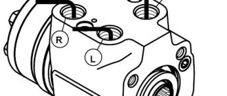
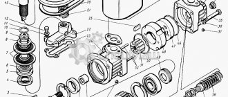
Fig.5. Steering mechanism (steering mechanism) KamAZ with built-in hydraulic booster 1 - front cover; 2 - power steering control valve; 3, 29 — retaining rings; 4 — floating bushing; 5, 7 — sealing rings; 6, 8 — spacer rings; 9 — set screw; 10 — bipod shaft; 11 — bypass valve; 12 — protective cap; 13 — rear cover; 14 — steering gear housing; 15 — piston-rack; 16 — magnetic drain plug; 17 - screw; 18 — ball nut; 19 - gutter; 20 - ball; 21 — angular gearbox; 22 — thrust bearing; 23 — spring washer; 24 - nut; 25 — thrust washer; 26 — adjusting washer; 27 — adjusting screw; 28 — lock nut of the adjusting screw; 30 — side cover The bracket is fixed to the car frame. Carter 14 of the Kamaz steering mechanism, in which the piston-rack moves, also serves as the working cylinder of the hydraulic booster. Screw 17 of the Kamaz steering mechanism has a ground helical groove. The same groove is ground in nut 18 and two holes are drilled into it. The holes are connected by an oblique groove milled on the outer surface of the nut. Two identical grooves 19 of semicircular cross-section, installed in the mentioned holes, and a groove form a bypass channel through which the balls 20, rolling out of the screw channel formed by the threads of the screw and nut, again enter it. To prevent the balls from falling out of the screw channel of the Kamaz steering mechanism, a tongue is provided in each groove that fits into the screw groove of the screw and changes the direction of movement of the balls. The number of circulating balls in a closed screw channel is thirty-one, eight of which are in the bypass channel. The helical groove on the screw in its middle zone is designed so that a slight interference is formed between the screw, nut and balls. This is necessary to ensure gap-free mating of parts in this area. When moving the nut, due to the fact that the depth of the groove on the screw from the middle to the ends increases slightly, a small gap appears in the mating of the screw and the nut. The specified gap is necessary to ensure greater durability of the middle part of the screw of the Kamaz steering mechanism, as well as to facilitate the return of the steered wheels to the middle position after turning and better stabilize the movement of the vehicle. In addition, loosening the seat of the ball nut on the screw towards the edges of its screw groove will make it easier to select the balls and assemble the ball screw pair. Since the transfer of axial force from the screw to the nut is carried out by means of balls, friction losses in the screw pair are minimal. After assembling the nut with the screw and balls, it is installed in the piston-rack 15 and fixed with two setscrews 9, which are cored into the annular groove made on the piston-rack. The piston-rack engages with the toothed sector of the bipod shaft 10. The Kamaz steering gear bipod shaft rotates in a bronze bushing pressed into the steering gear housing and into the aluminum side cover 30. The thickness of the teeth of the bipod shaft sector and the piston-rack is variable along the length, which allows you to change the engagement gap by moving the adjusting screw 27 screwed into the side cover . The head of the adjusting screw of the Kamaz steering mechanism, on which the thrust washer 25 rests, fits into the socket of the bipod shaft. The axial movement of the adjusting screw in the bipod shaft, maintained during assembly at 0.02 ... 0.08 mm, is ensured by selecting an adjusting washer 26 of the appropriate thickness. Parts of the Kamaz steering mechanism 27, 26, 25 are held in the bipod shaft socket by a retaining ring 29. The middle cavity between the rack teeth, which engages with the middle tooth of the gear sector of the bipod shaft, is made slightly smaller than the rest. This is necessary in order to avoid jamming of the worn steering mechanism after its adjustment when turning the bipod shaft. On the part of the screw of the Kamaz steering mechanism, located in the cavity of the angular gearbox housing, splines are cut with which the screw mates with the driven gear of the angular transmission. The Kamaz power steering control valve (Fig. 6) is attached to the bevel gear housing using a bolt and four studs (or five studs - one long and four short). Fig.6. Kamaz power steering control valve 1 - blind hole plunger; 2.5 - springs; 3 - threaded plug; 4 - check valve; 6 - spool; 7 — reactive plunger; 8 — valve body; 9 — sealing ring; 10 - safety valve Housing 8 of the Kamaz steering valve has a central hole made with great precision and six (three through and three blind) smaller holes located around it. The spool 6 of the Kamaz steering valve, located in the central hole, and the thrust bearings 22 (see Fig. 5) are secured to the screw with a nut 24, the collar of which is pressed into the groove of the screw 17. A conical spring washer 23 is placed under the nut, making it possible to regulate the tightening force of the thrust bearings. The concave side of the washer is directed towards the bearing. The large bearing rings face the spool. The Kamaz steering gear screw and the spool rigidly connected to them can move in each direction from the middle position by 1...1.2 mm. The amount of movement is determined by the depth of the recesses at the ends of the valve body and is limited by large bearing rings that abut the ends of the mentioned recesses. Two reaction plungers 7 (see Fig. 6) with centering springs between them are inserted into each of the three through holes of the valve body of the Kamaz steering mechanism. To ensure the same reactive force on the steering wheel of a Kamaz vehicle from oil pressure and the necessary equal active areas of the plungers when turning both right and left, plunger 1 is installed in each of the three blind holes facing the bevel gear. Total area of these three reactive elements is equal in size to the cross-sectional area of the screw at the point of its seal in the thrust cover of the angular gearbox of the Kamaz steering. One of the plungers, located in the blind holes, has a ball check valve 4 built in, which connects the high and low pressure lines in the event of a failure of the steering hydraulic system and thus ensures the ability to drive the car. In this case, the Kamaz steering operates like a conventional mechanical system without reinforcement. A safety valve 10 is also installed in the Kamaz steering valve body, connecting the injection and drain lines at a pressure in the system exceeding 7357.5 ... 7848 kPa (75 ... 80 kgf/cm2), and thus protecting the pump from overheating, and the parts mechanism from excessive loads. The safety valve is located in a separate boss, which makes it possible to check, adjust or replace its parts if necessary. The cavities located under the front cover 1 (see Fig. 5) and in the angular gearbox of the KamAZ steering are connected by holes in the control valve body with the drain line and sealed at the ends with rubber O-rings. Similar rings seal all the fixed connections of the steering mechanism and power steering parts. The shaft of the Kamaz steering bipod is sealed with a cuff with a special thrust ring that prevents the working edge of the cuff from turning out under high pressure. The outer cuff protects the bipod shaft from dust and dirt. The piston in the cylinder and the Kamaz steering gear screw in the bevel gear housing cover are sealed with fluoroplastic rings 5 and 7 in combination with rubber spacer rings 6, 8. The adjusting screw for the Kamaz steering bipod shaft is sealed with a rubber ring. The shaft seal of the drive gear of the angular gearbox is combined and consists of two cuffs, which are fixed with a split thrust ring. In the Kamaz steering gear housing there is a drain plug 16 with a magnet, which serves to catch steel and cast iron particles, and a bypass valve 11, which is used when filling and bleeding the steering hydraulic system. High and low pressure hoses and pipelines are connected from the pump to the Kamaz control valve body. The former directs the oil to the mechanism, and the latter returns it to the hydraulic system reservoir. Kamaz steering gear Kamaz steering gear includes longitudinal and transverse steering rods.
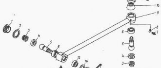
Fig.7. Longitudinal steering rod KamAZ 1 - ball pin; 2 — lining clip; 3 — protective cover; 4 — upper liner; 5 — lower liner; 6 — pressure spring; 7 — cover washer; 8 - cover; 9 — oiler; 10 — protective cover Kamaz longitudinal steering rod (Fig. 1) connects the bipod 9 of the steering mechanism with the upper arm of the left steering knuckle and is a solid forged part with non-adjustable hinges, including ball pin 1 (Fig. 7), upper 4 and lower 5 liners, a spring and a threaded cover 8 with a lock washer 7. The transverse rod of the Kamaz steering linkage (Fig. 8), included in the technological assembly unit “front axle assembly”, is tubular with threaded ends onto which ends 2 with ball joints are screwed. Fig.8. Cross steering rod Kamaz 1 - transverse rod; 2 - tip; 3 — tip fastening bolt; 4 — sealing gasket; 5 - oiler; 6 - cover; 7- spring; 8 — cover fastening bolt; 9 — protective cover; 10 — lining clip; 11 — ball pin; 12 — upper liner; 13 — lower liner By changing the position of the tips on the Kamaz steering rod, you can adjust the toe-in of the steered wheels. Each tip is fixed with two bolts 3. The Kamaz tie rod joints are also non-adjustable, consisting of a ball pin 11, upper 12 and lower 13 liners, a spring 7 and a cover 6 attached with a sealing paronite gasket 4 to the rod end with bolts 8. Lubrication of the steering rod joints Kamaz is produced through oil nipples 5. Rubber pads are used to protect the hinges from dust and dirt getting into them. Replace the Kamaz tie rod in the following order: — hang up the front axle of the vehicle; — unscrew and unscrew the nut securing the ball pin of the left rod end with the corresponding lower steering knuckle arm; — having knocked out the ball pin from the conical hole of the lever, disconnect the left tip of the steering linkage rod; — do the same operations with the right tie rod end and remove the tie rod from the car; — install the ends of the ball pins of the new transverse link ends in the holes of the lower arms, tighten and cotter the fastening nuts. The tightening torque of the tie rod ball pin nuts is 245…314 Nm (25…32 kg/cm). Install the transverse link so that the ball pin grease fittings on the link ends face rearwards in the direction of the vehicle; - lower the front axle. To replace the longitudinal steering rod of a Kamaz: - lift the front axle of the vehicle and turn the steered wheels to the left until they stop; — unscrew and unscrew the nut securing the ball pin of the longitudinal steering rod on the side of the steering bipod; — having knocked the ball pin out of the conical hole of the bipod, disconnect the rod; — perform the same operations with the other hinge joint of the longitudinal link at the point where it connects with the upper arm of the left steering knuckle and remove the link from the car. Install the new Kamaz steering rod in the reverse order of removal, paying attention to the correct connection and the correspondence of the different rod heads to the installation locations. Lower the front axle of the vehicle. Tighten the Kamaz steering rod ball pin nuts with a torque of 245... 314 Nm (25... 32 kg/cm).
Checking and adjusting the steering of the KamAZ-5320, 55111, 4310 vehicle The technical condition of the steering of the KamAZ-5320, 55111, 4310 is generally assessed by the amount of free play of the steering wheel. To check it, it is necessary to install a equipped Kamaz-5320, 55111, 4310 vehicle on a horizontal platform with the steered wheels in the position for straight-line movement. The tire pressure of the front wheels should be 730 kPa (7.3 kgf/cm2); The hydraulic steering system must be filled and bled. The free play of the steering wheel at engine operating modes in the range of 600–1200 rpm should not exceed 25° (for new cars 15°). If the specified values increase, it is necessary to check the fastenings of the steering wheel, column, and cardan transmission of the KamAZ-5320, 55111, 4310 steering mechanism; the condition of the hinges, the attachment of the bipod, the adjustment and fastening of the steered wheels. If the steering wheel is axially displaced, nut 5 should be tightened (see Fig. 6.1) with a tightening torque of 30–80 Nm (3–8 kg/cm). The torque of the shaft rotation when the cardan drive is disconnected should be in the range of 60–80 Nm (6–8 kg/cm). Excessive tightening of the nut and then loosening it is unacceptable, as this may damage the seals and bearings. Carrying out fastening operations is permissible subject to the following conditions: the tightening torque of the steering wheel fastening nut must be in the range of 60-80 (6-8), the universal joint drive wedge nuts 14-17 (1.4-1.7), the bipod mounting bolts 180 -320 (18-32), wheel nuts 250-300 Nm (25-30) kg/cm. In addition, you should check the installation of the steered wheels, the presence of lubrication in the parts and assemblies of the steering and wheel hubs. Checking and adjusting the steering mechanism of KamAZ-5320, 55111, 4310 is carried out with the longitudinal steering rod disconnected and the amplifier inoperative. The force on the steering wheel rim is measured with a dynamometer in its various positions. When turning the steering wheel more than 2 turns from the middle position, the force should be in the range of 6-16 N (0.6-1.6 kgf). When turning the steering wheel 0.75-1 turn from the middle position, the force should not exceed 23 N (2.3 kgf). As the steering wheel passes through the middle position, the force on the rim should be 4–6 N (0.4–0.6 kgf) greater than in the second position, but not exceed 28 N (2.8 kgf). The steering parameters of KamAZ-5320, 55111, 4310 are adjusted by shifting the gear sector while rotating the adjusting screw in the steering mechanism cover. When the screw rotates clockwise, the force when turning the steering wheel increases in the opposite direction - decreases. The axial displacement of the adjusting screw should be in the range of 0.02-0.08 mm. A discrepancy between the forces on the steering wheel rim in the first position indicates the need to adjust the spool thrust bearings. The bearings are adjusted by tightening the nut with the front cover removed. A change in the forces on the steering wheel rim in the second position may be caused by damage to the ball nut or wear of its parts. Checking and adjusting the fluid pressure in the hydraulic booster (power steering) KamAZ-5320, 55111, 4310
Before checking, it is necessary to warm up the engine and oil in the tank by several turns of the wheels until they stop, holding for 10-15 seconds. Install a device with a pressure gauge with a scale of up to 10,000 kPa (100 kgf/cm2) and a valve in the high-pressure line between the pump and the steering mechanism. Open the valve and, working at a crankshaft speed of 600 rpm, measure the oil pressure using a pressure gauge. The oil pressure must be at least 5500 kPa (55 kgf/cm). At lower pressures, you should slowly close the valve and evaluate the change in its value. If the pump is working properly, the oil pressure should increase to 6000 kPa (60 kgf/cm2) on a new pump; on a repaired one, the safety valve should be adjusted. If the oil pressure does not rise when the valve is closed, the pump should be replaced or repaired. The noise that occurs when the safety valve operates does not indicate a malfunction. When checking the operation of the control valve of the Kamaz-5320, 55111, 4310 hydraulic booster, you should disconnect the longitudinal link, set the engine speed to 800-1000 rpm, and with the valve open, turn the steering wheel all the way left and right with a force of at least 100 N (10 kgf) . With the force removed from the steering wheel, the oil pressure should drop to 300-500 kPa (3-5 kgf/cm2), indicating that the control valve spool has shifted to the middle position under the influence of reaction springs and plungers. If the oil pressure does not decrease, you should check whether the plunger holes are dirty, whether the springs are weakened, or whether the spool is jammed in the control valve body. During the inspection process, do not keep the valve closed and the wheels turned all the way for more than 15 seconds. Maintenance of steering control Kamaz-5320, 55111, 4310 During the operation of Kamaz-5320, 55111, 4310 vehicles, it is necessary to clean steering controls, check the fastenings and condition of hoses of parts, adjust mechanisms and components, lubricate components and parts, remove air from the hydraulic system amplifier, add and periodically change the oil at the times specified in the lubrication chart. The oil level is checked on a warm Kamaz-5320, 55111, 4310 engine when the wheels are set to the straight-line position. Before removing the filler plug, wipe the surface of the tank. Oil is added when the engine is running at low shaft speeds through a funnel with a double mesh; the oil level should be between the marks on the indicator fixed in the plug. To avoid jamming and wear of carefully machined parts of the pump, steering mechanism, and control valve, only clean oil should be used. Changing the oil in the steering of a KamAZ-5320, 55111, 4310 vehicle is carried out with the longitudinal steering rod disconnected. To drain the oil, you need to remove the pump cover and turn the steering wheels to the left until they stop, unscrew the steering gear drain plug and drain the oil. Then remove and wash the filter and pump parts in gasoline, if there are viscous deposits, use a solvent for washing, and put the parts back in place. Screw in the drain plug. Pour in 2 liters of clean oil and, turning the steering wheel all the way in both directions, flush the amplifier system and drain the oil again. Screw the plug back in, replace the reservoir cap, and remove the rubber cap from the steering gear bypass valve. Place a hose onto the bypass valve head. Lower its second end into a transparent vessel with a capacity of at least 0.5 liters, half filled with oil. Pour oil through the filler neck and into a funnel with a double mesh until the level stops decreasing. Having unscrewed the bypass valve 0.5-0.75 turns, turn the steering wheel to the left until the force begins to increase (not all the way). Start the KamAZ-5320, 55111, 4310 engine and, working at low shaft speeds, add oil to the tank until the release of air bubbles from the hose stops, then close the valve. Repeat a similar operation when turning the steering wheel to the right, and so on at least two or three times until the air flow stops. After this, you should stop the engine, remove the hose, put on the rubber cap if you need to add oil to the tank, close the tank lid and connect the longitudinal rod.
_______________________________________________________________________________
_______________________________________________________________________________
_______________________________________________________________________________
- Clutch KamAZ-5320 and its components
- Repair of PGU and Kamaz clutch master cylinder
- Gearbox gearbox KamAZ 141
- Gearbox gearbox KamAZ ZF 16
- Gearbox 152 Kamaz with divider
- Gearbox gearbox 154 Kamaz
- Gearbox Kamaz-4308
- Clutch of a Kamaz-4308 car
- Clutch and gearbox KamAZ-65115
- Disassembly and assembly of Kamaz-4310, 55111, 43118 gearboxes
_______________________________________________________________________________
- Cylinder block, head and valves Kamaz-740
- Fuel system of Kamaz-740 diesel engine
- Adjustments and repairs of fuel injection pump Kamaz-740
- Drive axles of the Kamaz-4310 vehicle
- Repair of Kamaz drive axle gearbox
- Rear axle KamAZ-4308
- Axles and suspensions of Kamaz-65115 dump trucks
- Installation of Kamaz cardan shafts and axles
- Repair of Kamaz vehicle transfer case
- Kamaz power steering - adjustments and repairs
- Repair of Kamaz steering gear parts
- Steering parts Kamaz-4308
- Parts of the brake system Kamaz-4308
- Brake system and brake drive Kamaz
- Repair of brake valves and Kamaz compressor
- Suspension Kamaz-4310, 55111, 43118 and their parts
- Frame and suspension of the Kamaz-4308 car
- Cabin details and platform KamAZ-65115
- Cabin components Kamaz-4308
- Platform mechanism of Kamaz vehicles
- Klintsy KS 65719-5K truck crane based on KamAZ-6522 chassis
- Truck crane KC-35719-7-02 based on Kamaz-43118 chassis
- Truck crane Galichanin KC-55713-1K based on KamAZ-65115 6x4
- Ivanovets KS-45717K-1/1R truck crane based on KamAZ-65115 chassis
- Ivanovets KS-3577-3/4 truck crane on KamAZ-43253 4x2 chassis
Operating principle of the steering gear
This is part of the control system that directly rotates the front wheels to a given degree. It includes longitudinal and transverse thrust, which, in turn, consist of:
- ball pins;
- upper and lower liner;
- oilers (on each rod separately);
- sealing gaskets;
- auxiliary components - lock washers, springs, etc.
The transverse link is part of the KAMAZ front axle assembly as a technological unit. The longitudinal link is a single piece; its hinges are not adjustable. It transmits force from the bipod of the mechanism to the upper arm of the left steering knuckle.
The hinges contain ball pins, which are the main elements of the device.
Video on the topic: Steering control of Kamaz 4310 and Kamaz 5320 vehicles
Publications on the topic
Design features of the KamAZ 4310 truck
Main characteristics of the legendary KamAZ 5320
Features of diagnostics and repair of the KamAZ 5320 gearbox
Wheel alignment on KamAZ - How to do it right
When it comes to driving safety, some drivers neglect to properly configure the car's wheels. Meanwhile, the unit affects the service life of the vehicle, and the KamAZ wheel alignment plays a major role here.
The setting of the parameter is influenced by many indicators, such as the vehicle load, the level of air pressure in the tires, etc. That is why, in order to correctly adjust the toe-in on a KamAZ, as many of them as possible are taken into account. There is no exact period; this factor is based on the driver’s experience, knowledge of the structure and behavior of the car. Based on a number of indicators and signs, you can clearly orient yourself about the coming moment. Let's look at this issue in detail.
When to adjust wheel toe
Before adjusting the toe-in of KamAZ 5320 wheels, you need to clearly determine the feasibility of the procedure. The adjustment is made to increase the clarity in driving, as well as to improve the stability of the vehicle. In addition, proper adjustments will better preserve your tires and eliminate uneven wear.
The following signs indicate the need for work:
- The car pulls to the side when driving straight;
- Mechanisms affecting vehicle control have been replaced;
- Frequent driving on poor road surfaces;
- The vehicle's service mileage has been exceeded.
KAMAZ steering knuckle:
Only the owner of the vehicle knows about the need to perform a wheel alignment on KamAZ. Because he alone knows about the nature and types of manipulations on the machine. As a rule, service workers perform the procedure once every six months, based on average mileage. But, if the car does not pass these standards, frequent adjustments are no longer advisable.
Settings are made in the following cases:
- Buying a new car. In such a situation, the seller is obliged to perform alignment at KamAZ, however, the procedure is performed extremely rarely. The buyer is recommended to check the work themselves to be sure of the condition of the car.
- Seasonal change of tires (winter - summer or summer - winter). Checking the correct settings is carried out due to changes in the characteristics of the wheels. The diameter and width of the tires change, this is reflected in the technical performance of the car.
Rectilinear movement is accompanied by the car drifting to the side. The procedure for checking the geometry of the car is carried out as quickly as possible, since this behavior is typical for vehicles with impaired wheel alignment. An investigation is necessary if the behavior manifests itself on a smooth, paved road.
Wheel alignment test stand:
- Characteristic wear of car tires. Impaired wheel alignment wears out tires in different ways. This is reflected on the tread surface. Based on the tread pattern and the nature of wear, it is judged which of the characteristics is violated.
- Every 15,000-20,000 kilometers. When a Kamaz car goes through a mileage, the car is inspected. Procedures are performed to maintain the machine in the required technical condition and prolong its performance. The list of works includes the procedure for setting up and adjusting wheel alignment. The older the car, the more often adjustments are made.
Parameters affecting driving
The procedure for adjusting the steered wheels is to control and bring the parameters to the desired value. In our case, these are the angles at which the wheels are aligned:
- Camber;
The parameter is determined by the difference between the vertical deviation values;
- Transverse inclination of the hinge rod;
The parameter is determined by attaching the hinge rod to the bridge boss and measuring the angle of deflection of the wheel axis in the transverse plane;
- Longitudinal inclination of the hinge rod;
The parameter is determined by installing the hinge rod in the boss of the beam and monitoring the angle of deflection of the axis in the longitudinal plane. Depends on the position of the front spring and frame;
- KamAZ front wheel alignment. Linear value characterizes the distance (rim of the steered and rear wheels).
Scheme for installing steered wheels on KamAZ:
The tilting of the hinge rods aligns the car's wheels, and the adjustment returns them to the straight position automatically. The lateral position of the change causes the front of the car to rise when the wheels are turned. The mass of the car prevents the beam from rising and returns the wheels to straight space. The longitudinal position forms a lever between the axle and the place where the lateral force is applied.