KAMAZ 43118 description of the instrument panel
Overview of the interior and controls of KAMAZ 65221)))
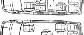
Cabin structure of KamAZ 43114
KAMAZ Euro-3 instrument panel assembled.
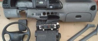
KAMAZ dashboard
Kamaz colt start euro 4
KAMAZ 65115
Automotive simulator "KAMAZ-Master-01" (original dashboard of a KamAZ car)
KamaZ generator operation.
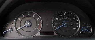
Speedometer KAMAZ Euro 3
CAN Rewinding the Kamaz euro4 speedometer into the OBDII connector www.odovrn.ru
Also see:
- Automotive lamps for KAMAZ
- KAMAZ 6520 body heating circuit
- Battery connection diagram for KAMAZ
- How to increase the sides on a KAMAZ dump truck
- Compress tube KAMAZ
- KAMAZ 6520 three-way unloading
- KAMAZ engine lubrication system presentation
- Automarket KAMAZ trucks
- Is it possible to weld a frame from KAMAZ?
- Type of fuel pump KAMAZ 740
- Why KAMAZ master wins
- Codes for GTA Vice City KAMAZ
- Overturned KAMAZ on the Moscow Ring Road
- Piglet KAMAZ what is it
- Flywheel bearing KAMAZ 6520
Home » Video » KAMAZ 43118 description of the instrument panel
kamaz136.ru
Technical specifications in numbers
- Overall dimensions: length – 7.570 m, width – 2.900 m, height – 2.900 m, height with the platform raised back – 5.920 m;
- Wheelbase – 3,190 (+1,320 m);
- The front track size is 2.026 m, the rear track size is 1.856 m;
- Ground clearance – 280 mm;
- Outer turning radius – overall: 9,300 m, on the outer wheel – 8,500 m;
- Curb weight - 8,480 tons;
- Front axle load – 4.5 tons;
- Load on the rear bogie – 11,130 tons;
- Load capacity – 7 tons;
- Gross weight - 15,630 tons;
- The permissible trailer weight is 11.5 tons.
- The greatest rise a car can overcome is 30 percent.
Controls in the cab of a truck crane based on KAMAZ
Cabin of truck crane KS-45721 Chelyabinets 25 tons
Truck crane Ivanovets
Cabin of truck crane KS 45721 Chelyabinets 25 tons
Russian miracle crane "OVOID"
Review of the Chelyabinets KS-55733-33 truck crane KamAZ 63501 | Ural Special Equipment Plant
Crane manipulator KANGLIM KS2056H Control
Automated training system “Crane operator”
IVANOVETS truck crane with ovoid boom
Kamaz 5511 mixer unloading concrete
Truck crane Chelyabinets KS 45721, 25 tons, Kamaz 43118 id3279
Also see:
- Put sloth on KAMAZ
- How to remove a hub on a KAMAZ
- KAMAZ from state storage 55111 and 65115 or conservation
- Spoiler for KAMAZ with maxi roof
- Assembling and disassembling the KAMAZ starter
- Diagram of air movement in the KAMAZ brake system
- Hydrogen at KAMAZ
- Wheel hub bearing KAMAZ 4310
- KAMAZ injection pump tubes diagram
- KAMAZ engine degassing
- Auto KAMAZ next
- Color wiring diagram KAMAZ 43114
- Steel grade for KAMAZ springs
- Starter retractor KAMAZ
- KAMAZ problem with charging
Home » News » Controls in the cab of a truck crane based on KAMAZ kamaz-parts.ru
Advantages and disadvantages
KamAZ trucks marked 4308 have the following advantages:
- low fuel consumption;
- high load capacity with low-frame design;
- the ability to install additional equipment and add-ons on the vehicle chassis;
- low cost of the car;
- availability and low price of spare parts;
- high maintainability;
- presence of a powerful engine;
- starting a cold engine at low temperatures without relief means;
- independent heater function in the cabin;
- possibility of installing air suspension;
- small overall dimensions;
- automatic tensioning of the fan belt;
- aesthetic appearance of the dashboard;
- installation of cruise control in some modifications;
- comfortable seat.
Among the disadvantages are:
- frequent malfunctions in “weak” places, for example in gearbox pipes;
- uncomfortable position of the brake and gas pedals;
- impossibility of working off-road;
- the appearance of the car is outdated;
- lack of power for quick acceleration when loaded.
Dashboard KAMAZ 43118 euro 4 description
Kamaz colt start euro 4
Overview of the interior and controls of KAMAZ 65221)))
KAMAZ Euro-3 instrument panel assembled.
Cabin overview KamAZ 65117
CAN Rewinding the Kamaz euro4 speedometer in OBDII www.odovrn.ru
KAMAZ 65115
Cabin structure of KamAZ 43114
CAN Rewinding the Kamaz euro4 speedometer into the OBDII connector www.odovrn.ru
Review of restyled KamAZ 65115
ACVT-10 on KamAZ chassis 43118-3050-42
Also see:
- Low gear on KAMAZ
- Cardan on fuel injection pump KAMAZ Euro 2
- Shoe roller with KAMAZ axle
- KAMAZ cab locks
- Spare parts for KAMAZ 16s151 gearbox
- Oil channels clogged KAMAZ engine
- Beading of KAMAZ doc wheels
- KAMAZ crane center
- Overload on KAMAZ axle
- The purpose of the KAMAZ checkpoint
- How to make the cabin softer on KAMAZ
- KAMAZ parking brake and connection diagram
- KAMAZ 552900 agricultural dump truck
- KAMAZ waste was detained
- Meeting with the KAMAZ master team
Home » The best » Dashboard KAMAZ 43118 euro 4 description
kamaz-parts.ru
Vehicle device
45141-10 is presented in two modifications. The difference is in the number of beds. In one it is, in the other it is absent. KamAZ 45141 is equipped with a cabin made of high-strength metal alloy. The cabin is inclined, above the engine. Lifting is possible thanks to a hydraulic lift, but for the driver’s convenience (to avoid excessive noise) the cabin is closed with thermal insulation.
KamAZ 45141 is equipped with an all-metal box-type platform that can withstand significant weights. There are welded elements, a sloped front side, and a protective canopy to prevent the loss of cargo. The rear part has an opening side with a slope. The machine can withstand unloading in any season, this is helped by platform heating using exhaust gases. The material does not freeze.
The dump truck mechanism allows the platform to move. Lifting occurs thanks to a three-stage hydraulic cylinder. Uniform distribution of the spilled cargo can be controlled by a hydraulic cylinder from the driver's cabin.
Modifications to the main model
Currently, there are several modifications of KAMAZ - 4308-6011-C5(86). They differ only in the configuration. The technical parameters are the same for everyone.
The modifications are as follows:
- KAMAZ 4308-6063-69 (G5) - Cummins ISB6.7E5 250 (E-5) engine, BOSCH injection pump, neutralization system. Exhaust gas (AdBlue), ZF6S1000 gearbox, awning, frame, internal. platform dimensions 6112x2470x730 mm, Russian standard tachograph with CIPF unit;
- KAMAZ 4308-7063-69(G5) - Cummins ISB6.7E5 250 (E-5) engine, BOSCH injection pump, neutralization system. Exhaust gas, ZF6S1000 gearbox, awning, frame, internal platform dimensions 6112x2470x730 mm, rest-2, Russian standard tachograph with CIPF unit;
- KAMAZ 4308-6083-69 (G5) - Cummins ISB6.7E5 250 (E-5) engine, BOSCH injection pump, neutralization system. Exhaust gas (AdBlue), ZF6S1000 gearbox, rear air suspension, awning, frame, internal platform dimensions 6112x2470x730 mm, Russian standard tachograph with CIPF unit.
KAMAZ 4308-7063-69
Advantages
At the commercial vehicle exhibition in 2007, KamAZ 4308 won the category as the best domestically produced truck. This is easy to explain - this model has many advantages:
KamAZ-4308
- large load capacity – 5.5 tons;
- economical fuel consumption;
- low loading height;
- maneuverability in city conditions;
- convenient use as part of a road train;
- the ability to install additional equipment, which greatly expands the scope of application of the machine;
- affordable price.
The cheapness of this truck, relative to foreign analogues, has become one of the main reasons for its popularity. It is easy to find the necessary spare parts for it and inexpensive to buy. Therefore, many entrepreneurs prefer to have a new car, simple and easy to maintain, than a used and expensive one.
The combination of this factor with excellent technical characteristics gives the truck high praise from drivers and owners.
Error codes with explanations
See the most common error codes below:
| Error code ADM3 SPN | ADM3 FMI error code | Error code ADM3 (K-line) | Error code MR2 (K-line) | Error Location | Description of the error |
| 51 | — | 12419 | Throttle position | Above measuring range | |
| 51 | 1 | — | 12420 | Throttle position | Below measuring range |
| 51 | 2 | — | 12424 | Throttle position | Measuring range is not possible |
| 51 | 2 | — | 14217 | Throttle position | Characteristics |
| 51 | 3 | — | 14205 | Throttle Position Sensor | Short circuit to high level |
| 51 | 4 | — | 14206 | Throttle Position Sensor | Short circuit to low level |
| 51 | 7 | — | 12431 | Throttle position | Defective |
| 51 | 13 | — | 14218 | Throttle position | Position outside |
How does the pneumatic drive of brake systems work?
Operation of the service brake system drive
Compressed air from the compressor flows through the pressure regulator and antifreeze guard to the safety valve block. It consists of double and triple valves that fill the receivers of all circuits of the brake systems with air.
The safety valves are adjusted so that first the receivers of circuit III (parking and spare brakes) are filled, and then the receivers of the remaining circuits.
Air from receivers with a capacity of 40 and 20 liters enters the corresponding sections of the brake valve. When you press the brake pedal, air from the lower section through the pressure limiting valve enters the brake chambers (type 24), which operate the brake mechanisms of the front axle wheels. From the upper section of the valve, air is supplied through the brake force regulator to the brake chambers (type 20), which activate the brake mechanisms of the wheels of the middle and rear axles. At the same time, air is supplied from both service brake circuits through separate lines to the trailer brake control valve with a two-wire drive.
Operation of the spare brake system drive
The parking brake valve has a tracking device that allows you to slow down the car with an intensity depending on the position of the brake valve handle.
When the tap is turned, air is released from the control line of the accelerator valve, the amount of which is proportional to the angle of rotation of the handle. In this case, through the atmospheric outlet of the accelerator valve, a corresponding amount of air leaves the cylinders of the spring energy accumulators. Simultaneously with the braking of the car, the trailer or semi-trailer is braked.
Operation of the parking brake system drive
To brake a car or road train on a riser, it is necessary to install the brake valve handle in the rear fixed position. At the same time, air from the control line of the accelerator valve escapes into the atmosphere. At the same time, air is released from the cylinders of the energy accumulators of the brake chambers through the atmospheric outlet of the accelerator valve. The springs, unclamping, activate the brake mechanisms of the rear and middle axles. At the same time, the brake valve turns on the trailer brake control valve with a two-wire drive.
To release the parking brake, the brake valve handle should be set to the front fixed position. In this case, the air from the receivers passes through the brake valve and enters the control line of the accelerator valve, which is activated and begins to pass compressed air from the receiver through the bypass valve, bypassing the brake valve, into the spring energy accumulators. At the same time, the power springs are compressed and the trailer is released.
In the event of an emergency drop in pressure in the parking brake drive circuit, the spring energy accumulators are activated and the vehicle is braked. In order to release the brakes, you must use the emergency brake release system.
When you press the emergency brake release valve, compressed air from the air receivers through a three-line safety valve and a bypass valve will enter the cylinders of the spring energy accumulators and compress the springs, releasing the car.
If there is no supply of compressed air in the emergency brake release circuit, the vehicle can be released using devices for mechanical brake release, which are built into the cylinders of spring energy accumulators. To do this, turn the screw all the way. At the same time, it will rest against the bottom of the piston through the thrust bearing and lift it up, compressing the power spring of the energy accumulator. The pusher, rising, will release the brake chamber rod, which will rise upward under the action of the return spring. The springs will tighten the pads and the car will release the brakes.
Operation of the auxiliary brake system drive
When you press the auxiliary brake valve, compressed air from the receiver enters the pneumatic cylinders. The cylinder rod connected to the fuel pump rack lever will move and the fuel supply will stop. The cylinder rods connected to the auxiliary brake flap levers will turn the flaps, and they will block the exhaust pipes of the muffler.
The contacts of the pneumoelectric sensor installed in the line in front of the cylinder will close, and the trailer's solenoid valve will turn on, which will partially allow compressed air from the trailer's air cylinder into its brake chambers. Thus, the trailer is slowed down, which prevents the road train from “folding.”
Basic faults
| Cause of malfunction | Remedy |
| ENGINE | |
| The engine does not start | |
| Lack of fuel in the fuel tank | Fill the fuel tank and bleed the fuel system |
| Presence of air in the fuel supply system | Eliminate leaks and bleed fuel system |
| Failure to adjust the fuel injection advance angle | Adjust the fuel injection advance angle |
| Increased oil consumption | |
| Prolonged engine operation at idle speed | Do not operate the engine at idle speed unless necessary. |
| Oil leakage through connections in the turbocharger lubrication system | Tighten connections and, if necessary, replace gaskets and sealing rings of the turbocharger |
| Wear of the valve-bushing interface in the cylinder head, aging of the rubber valve seal | Check and, if the wear limits of the valve stem diameter - 0.05 mm and bushing - 0.2 mm are reached, replace the worn parts |
| Air cleaner or air intake hood clogged | Maintain the air cleaner or clean the air intake hood mesh |


