I'll start from far away! In the summer, my partner was driving his KamAZ 43118 truck crane through a ford, and at that moment the electric coupling of the cooling system must have turned on. The result was a water hammer and the plastic fan shattered into pieces! The result was disastrous! Radiator - in half! The intercooler is distorted! The wires that go to the ECU, which is attached by idiotic designers to the front of the internal combustion engine, have been cut off! The truck crane stands dead in the middle of the stream! They called URAL-WATCH from the base to drag the poor fellow to the base! What am I talking about? Yes, I have the same system as on that truck crane! The electric coupling is activated automatically by a simple classic temperature sensor which turns it on to cool the radiator. All! The designers thought that was enough! But the fact is that the sensor itself is in an inaccessible place - under the generator! And to unscrew it you need a special deep socket with an extension, they don’t care! And they don’t care that a 12V sensor from a classic is installed on a car with 24V, and that it burns out five times a month! Kick-ass, for whom and for what are cars being improved? Why did KAMAZ vehicles with EURO 3 and 2 have keys for switching the electric coupling, but these EURO 4 vehicles do not have them? Why are we so unlucky! Were they smoking other dope at the factory at that time? And if the sensor itself fails, the car will soon stop due to overheating of the internal combustion engine! Totally fucked up! Well, in general, I decided to get confused and introduce myself a key to switch and disable the electric coupling like I had on the MAZURIK, fortunately it’s not difficult, if only I had the desire! And so, we buy a three-core electrical wire of stupid squares, about three meters. If possible, we put the wire in a protective corrugation and find routes from the cockpit from the power button to the clutch engagement sensor! It was not possible to take a photo of the sensor itself and the connection, because... It's hard to get there. When I connected, I disconnected the wire, pulled it out to an accessible place and cut and twisted it! In general, a negative wire approaches the sensor and breaks at the sensor! I broke one wire and connected it to two wires, and paralleled the third with the second wire, simple! I connected it to a three-position key, if you mix up something in the connection, it’s not a big deal, you can rearrange it during use! Now, in the upper position, the clutch is turned on forcibly - if the sensor fails, the middle mode is automatic, and the lower position is completely turned off, so that there is no problem like with my partner’s truck crane! Because all the factory troubles are connected via a relay, then I don’t bother with the relays anymore! By the way, its repair resulted in 60 thousand Russian mowers. And my entire design cost 200 rubles! Who will pay me extra 59,800 rubles? And I also connected an LED light that turns on when the clutch is activated! So purely for myself, it was like that at MAZ, I’m used to it! I connected one wire from the diode to the plus, the second to the key, on which all the wires are minus! It seems like that! If you don't understand anything, ask! Good luck to all!
The KamAZ brake system is thought out to the smallest nuances, since the technical condition of the vehicle and the possibility of safe driving depend on it. The installed KamAZ speed sensor is an important device, as it allows you to monitor the technical performance of the vehicle.
Where is the speed sensor located?
In most cases, the sensors are located at the gearbox and are connected by a special drive to the speedometer, the data of which is read to determine speed and mileage.
Thus, it is advisable to find functional units taking into account the layout of a specific KamAZ model and the specifics of the technical system. The devices have different designs, since the influence of the location of the unit is noted.
Contact sensors are considered less reliable due to the interaction of spare parts and constant rotation. However, such devices are often used, as they are installed instead of a mechanical speedometer drive and allow you to modernize brake systems. Contact models are characterized by optimal reliability.
Sometimes on KamAZ, speed sensors can be installed without direct contact with the rotating shaft. To measure speed, a drive disk or rotor is often used, since this device is auxiliary. Contactless models are becoming in demand, as a result of which they are often installed on modern KamAZ models.
The KamAZ zf speed sensor is also popular, as it is created according to modern standards. The package includes a modern transfer case that increases reliability. A working unit allows you to find out the exact technical characteristics of the vehicle. Over the past few years, such devices have been successfully used on domestic vehicles, including KamAZ. Motorists remain satisfied, because with proper regular maintenance, additional benefits are noted, or rather, economical fuel consumption and a minimal amount of substances released into the air.
Fact! Any sensors work only on physical principles. Contact devices usually use the Hall effect and magnetoresistive effect (MRE), optocouplers. Non-contact sensors most often operate on the Hall effect and much less frequently on MRE.
Malfunctions of the service brake system
Ineffective braking of the car when you press the brake pedal occurs if the brake valve drive is out of alignment or the two-section brake valve is faulty.
If, during braking, the pressure in the brake chambers is nominal, then the wheel brake mechanisms are misaligned or faulty.
If, when braking with the service brake, the pressure is below normal only in the brake chambers of the front axle, then either the lower section of the brake valve or the pressure limiter is faulty.
If the pressure in the brake chambers is normal, but braking is not effective, then the stroke of the brake chamber rods is greater than normal, or, for example, the brake linings are oily.
When you press the brake pedal, the braking of the wheels of the rear cart is ineffective or does not occur at all (the front wheels brake normally).
Important Technical characteristics of South Korean light trucks Hyundai Porter (Hyundai Porter)
In the pneumatic part of the drive, the upper section of the brake valve or the brake force regulator may be faulty. In the mechanical part, the brake mechanisms or the drive of the brake force regulator lever are faulty or misaligned.
If, after releasing the brake pedal, all the wheels of the car do not release the brakes, then the two-section brake valve is faulty (the pusher or the upper piston is jammed). It is possible that the brake valve drive is out of adjustment (there is no free play of the brake pedal).
If air does not come out of the rear brake chambers after releasing the brake pedal, the brake force regulator or the upper section of the brake valve is faulty. These malfunctions lead to a delay in the release of air from the front brake chambers. If, when releasing the brakes, air is not released only from the front brake chambers, then the pressure limiter or the lower section of the brake valve is faulty.
Air leaks from the atmospheric outlet of the pressure limiter or brake force regulator during braking indicate malfunctions of these devices.
The cause of air leaks from the atmospheric outlet of a two-section brake valve can be not only the sealing rings and valves in the valve itself, but also other devices of the brake system.
If air leakage from the atmospheric outlet of the brake valve is observed when the pedal is released and the parking brake is applied, then the brake valve is faulty. When the engine is not running, using the standard two-pointer pressure gauge, you can accurately determine which section of the valve is leaking: if the upper arrow of the pressure gauge falls, the lower section of the valve is leaking; the lower arrow falls - the upper section is leaking.
If air leakage from the atmospheric outlet of the brake valve is observed only when the parking brake is released, and stops when applied, then the trailer brake control valve with a two-wire drive or one of the energy accumulators is faulty.
A faulty device can be determined by supplying air to the energy accumulators from the emergency brake release circuit: if, when you press the emergency brake release valve button, the leakage from the brake valve continues, then the pusher seal in the energy accumulator body is leaking, and if there is no leak, then the diaphragm in the trailer brake control valve is faulty.
Air leakage from the atmospheric outlet of the brake valve during braking indicates leakage of valves or o-rings in the device itself.
Operating principle of the speed sensor
Most sensors operate on the Hall effect. To determine speed and mileage, frequency pulses are used, which are sent at a certain interval. Impulses arise when the wheels rotate, so the mechanics calculate the data and they are displayed on transport devices. Typically, up to 6 thousand signals are issued for every kilometer. The KamAZ Euro speed sensor is considered the most advanced, since it was created on the basis of modern standards and European experience in the automotive sector, and is distinguished by its information content and accuracy.
Contact sensors
The basis of such devices is a corresponding microcircuit with a special plate and an amplification circuit. The chip and magnet do not move. To change the magnetic field and read pulses, rings with special slots rotate. The presence of small connectors allows you to read indicators for display on devices. The old-style KamAZ 5320 speed sensor was made using this principle.
Non-contact sensors
The device operates on the Hall effect, but the design is different. On the shaft of the unit (gearbox or axle gearbox) there is a rotor or impulse disk with areas that are magnetized. There is a gap between the Hall chip and the rotor, but pulse signals are successfully read through standard connectors. This KamAZ speed sensor circuit is considered reliable, since spare parts interact less with each other and unwanted mechanical influence is prevented.
Purpose, device and principle of operation
The suspension design includes elements such as:
- Electronic type sensor for acceleration. This device makes it possible to track the level of body tilt, its position relative to the road and acceleration.
- Compressor. It is necessary to supply compressed air flows to the receiver.
- Front and rear rack. With its help, the ground clearance is adjusted. This can be done either automatically or manually.
- Receiver and balancing device bracket. Adapts the operation of suspensions and facilitates the connection of all elements of the suspension mechanism.
- Control block. It is necessary for correct processing of sensor signals.
Air suspension is required for:
- ground clearance adjustment;
- transport alignment;
- improving truck handling and stability.
Principle of operation:
- The body level is maintained regardless of the vehicle load. Sensors continuously measure the distance of the wheels to the body part. At critical values, the valves of the lifting mechanism and the release valve are activated to lower the suspension mechanism.
- When the body height level changes, the speed of the suspension changes. The smoothness of the truck is analyzed and the height of the body is adjusted to suit the unevenness of the road surface.
Possible malfunctions of the speed sensor
KamAZ 55102, 65115 often have device malfunctions, because such models have been produced for a long time and there are numerous used models on the domestic market. Malfunctions are manifested by problems with idle speed (the car may stall), corrosive changes in contacts.
The KamAZ gearbox and speed sensor must be replaced, otherwise the following problems may appear:
- lack of information about mileage and speed due to inoperative devices;
- malfunction of the engine (impaired idling speed, excessive fuel consumption, loss of power);
- serious problems with security systems.
Note! Be sure to use a sensor that was installed earlier or recommended by the car manufacturer. If the unit is incorrectly selected, it will not be possible to install it, switching between speeds will not occur correctly, or the technical data will not be read correctly.
Speedometer functions
The sensor is primarily connected to the speedometer. For this reason, you need not only to know where the KamAZ speed sensor is located, to carefully monitor its serviceability, but also to take into account the functionality:
- speed measurement and display;
- displaying information about the distance traveled;
- informing about the current time;
- alarm about exceeding the permissible speed;
- measurement of the number of pulses for correct reading of characteristics.
Speed sensors on KamAZ 43118 vehicles and other models must be operational for safe driving, both in the city and on the highways.
Attention: The electronic auto parts catalog is intended for reference purposes! Our company only sells those products that have prices listed.
| Number | 43114-1800600 |
| Name | Installing replacement speedometer drive gears |
| Model | 43114 |
| Group | Transfer case |
| Subgroup | Transfer case assembly |
| Part serial number | 600 |
Part number on drawing:
Installing replacement speedometer drive gears
Serial number: 43114-1800600 Quantity per model:
| Number | 43114-3802033 |
| Name | Speedometer drive worm |
| Quantity for "KAMAZ 43118" | 1 |
| Model | 43114 |
| Group | Devices |
| Subgroup | Speedometer |
| Part serial number | 033 |
Part number on drawing:
Speedometer drive worm
Serial number: 43114-3802033 Quantity per model: 1
KAMAZ
In warehouses: 12 pcs.
| Number | 43114-3802034 |
| Name | Speedometer drive driven gear I=3.2 |
| Quantity for "KAMAZ 43118" | 1 |
| Model | 43114 |
| Group | Devices |
| Subgroup | Speedometer |
| Part serial number | 034 |
Part number on drawing:
Speedometer drive driven gear I=3.2
Serial number: 43114-3802034 Quantity per model: 1
To connect all the electrical systems and devices in the car, an electrical network is used, which allows you to bring all the components together. The KAMAZ-65115 color wiring diagram is a diagram indicating all electrical elements, the use of which is important when repairing wiring. You can learn more about the elements of the circuit, as well as wiring faults, from this material.
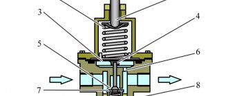
Pneumatic system pressure regulator
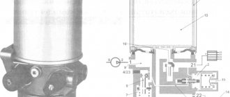
The pressure regulator is designed to automatically regulate pressure in the pneumatic system within the range of 0.65 0.8 MPa (6.5 8.0 KGS/SMZ), as well as to protect pneumatic drive units from contamination with oil and.
excessive increase in pressure due to failure of the regulating device. The pressure regulator is connected by a pipeline directly to the compressor; attached with two bolts to the bracket. The atmospheric outlet of the regulator is directed downward so that the condensate released by the regulator does not fall on other parts of the car.
Device
The speedometer on KamAZ is a device for measuring the speed of a vehicle. The device connects to a speed sensor and a topographer.
- mechanical;
- electronic;
- analog.
Analog can be:
- Pointer - speed is shown by moving the arrow across the dial.
- Tape - the location of the tape on the horizontal scale shows the speed.
- Drum - the indicator is placed on a drum that rotates in proportion to the change in speed.
A mechanical dial meter is installed on many machines.
Analog meter device:
- Worm unit, which is installed in the gearbox.
- A gear that rotates together with the gearbox shaft. This makes it possible to calculate the rotation speed of the drive and wheels.
- The wire that runs from the worm assembly to the instrument panel.
- Magnetic element.
- A metal plate attached to the arrow.
- Scale.
- Spring.
An accompanying element of the device is a counter, which determines the length of the path traveled and is connected to the cable via a worm gear.
In the electronic device, there is no mechanical connection between the data on the instrument panel and the transmission output shaft. The device is:
- Optoelectronic, in which there is a high-speed part with a cable, and the speed data is determined by photointerrupter pulses.
- Bestrosov, in which a magnet is installed, rotating in place with the gearbox shaft. Changes in the magnetic field are converted into pulses by the bridge circuit.
A popular meter that operates using the Hall effect. Changes in output voltage are proportional to the rotation speed of the disk. The frequency of the voltage pulses allows you to determine the speed of the machine.
Why does not it work
If the speedometer fails or does not work, the reasons may be as follows:
- The gears of the worm gear of the device are made of plastic. Since the material is fragile, this can cause the gears to break.
- The cable broke off where it connects to the speed system, which is screwed into the gearbox.
- The sensor contacts have oxidized or the power supply wire has broken. At the same time, the power is checked using a multimeter.
- There was a breakdown of the electronic part of the device located in the panel.
- There were distortions in the device readings. Most often this is due to instrument calibration, which is difficult to perform.
Speed is measured by the rotation of one axle of the final drive, and when turning, the wheel located on the inner radius travels a shorter distance than the outer one.
But the main reason for the inaccuracy of the data is the size of the wheels. The larger the wheel, the greater the distance the machine will travel in 1 revolution of the shaft.
The meters are mistaken by 5-10 km/h. Sometimes inaccurate data causes accidents. Therefore, car manufacturers, when calibrating electronic devices, make sure that the device on a new car does not show an underestimated speed.
Malfunctions and repairs
Main malfunctions and repairs of the regulator:
- If air leaks from the atmospheric outlet, the valve body must be cleaned or the defective valve and O-ring must be replaced.
- The device has stopped switching the compressor to idle mode. This problem can be caused by a clogged channel, pinching of the piston, or damage to the cuff. It is recommended to clean the valve, conduct an external inspection of the cuff and, if necessary, replace it with a new one, and also update the piston.
- The regulator stopped switching the compressor to the mode of filling the system with air. This malfunction is associated with clogged atmospheric orifice and intake valve, damaged spring, worn O-ring, tight piston part and worn valves. It is necessary to conduct an external inspection of the entire system for damage and defects, and if necessary, replace failed spare parts.
- Air leakage through the outlet into the atmosphere can be eliminated by replacing the filter element.
- When there is no supply of compressed air flow to the brake system of a vehicle, it is necessary to clean the check valve from accumulated contaminants or replace it if worn.
- If there is a small shaft between the on- and off-pressure level of the regulating device, damaged cuffs and rings should be replaced, valves and seats should be inspected and cleaned.
All repair work is carried out only with the engine switched off.
How to connect
The speedometer connection diagram, calibration and pinout instructions are available in the operating instructions for the device. At KamAZ, during manufacturing, the device is configured and a seal is installed on it. The need for adjustment arises when replacing a sensor, dump semi-trailer, wheels, axles.
The speedometer setting is as follows:
- KPPS is determined (coefficient of the speedometer indicating device);
- the value of the maximum speed is adjusted;
- the current time is adjusted.
KamAZ speedometers cannot be repaired. Their disassembly leads to malfunction. The meter is replaced by specialists.
If seals, connecting wires, or sensors have been broken, the warranty service of the device is terminated.
Seals are installed at the manufacturer.
Speedometers
Speedometer 87.3802010 or PA 8046-4P
Speedometer 81.3802010
Diameter 140mm, runs on 24 volt on-board network. It is mainly used on Kamaz or Maz trucks. There is a total and daily mileage counter and a speed limit alarm.
Speedometer 811.3802010
Diameter 140mm, runs on 12 volt on-board network. Suitable for GAZ, KAZ and PAZ.
Speedometer 85.3802010
Diameter 100mm, runs on 12 volt on-board network. Suitable for GAZ, UAZ and ZIL. Daily and total mileage counter. Very compact with a depth of only 7 centimeters.
You can buy these components from almost any supplier or at Avtopribor” in Vladimir.
tell me which sensor is suitable for the tachograph siemens vdo car maz 1999.
KamAZ speed sensor pinout
The speed sensor affects the amount of fuel supplied, as well as the amount of air that flows past the throttle valve. All these factors will affect the speedometer readings, therefore, for its connection and further proper operation, it must be carried out strictly in accordance with the diagram.
Pinout is a digital designation of connector functions, necessary for the correct order of connecting various parts and cables.
Modern KamAZ models, for example, 65115, are powered by Euro-3, Euro-4 and Euro-5 engines. Trucks with such engines are most often equipped with contact sensors located at the gearbox. The sensors on KamAZ of the Euro series are recognized as the most reliable in comparison with other models.
The principle of operation of the speed sensor is based on the supply of an impulse from the rotating wheels, which, when entering the device, is converted and, through the clutch with the speedometer, displays a certain numerical value on the LCD.
If the speed sensor is faulty, there may be problems with the engine idling, the car may not. In this case, the gearbox and speed sensor need to be replaced. You can independently configure the speedometer and motion sensor only in accordance with the pinout:
Description of KamAZ brakes
Each car produced by the Kama plant has four types of brake equipment on board.
- Main brake;
- Reserve brake;
- Stop brake;
- Auxiliary brake.
These types of equipment cope with the task without the need for mutual assistance, and as a result, the indicator of the work performed reaches efficiency. If automatic braking is accompanied by the release of air masses from the profile, the machine has an emergency release mechanism. The principle of using the device is to resume operation. Monitoring and signaling sensors for status and performance are also installed.
The main brake reduces the KamAZ speed limit, down to a complete stop. Vehicle stopping devices are located on six wheels of the vehicle. The operating principle of the drive is based on air under pressure. The unit is equipped with two circuits, the action of which extends to the bow and stern axles separately.
Activation of the main stopping mechanism occurs through a foot lever, which transmits the force to the brake valve. Brake chambers are converters of air pressure force into movement of brake pads.
The backup motion damper reduces the speed limit and stops the car when the main brakes fail or the function is not fully performed by the main device.
The stopping system forces the vehicle to remain stationary on a level surface, without intervention from the pilot. Feature of the stopping mechanism, paired with a backup brake. The activation is actual after the lever is moved to the required position.
KamAZ parking and auxiliary brakes:
From the above it is clear that at KamAZ the stopping methods used are the same for the main, backup and stopping motion dampers based on the stern. As for the backup and stopping dampers, they have the same pneumatic propulsion.
An additional motion damper works to reduce the degree of heating of the equipment, the main speed reduction device. This includes the power plant muffler, which switches the exhaust manifold, and turns off the fuel mixture input.
Emergency unlocking wedges the pads if they worked automatically and stopped the car. The emergency stop drive is double, activated both by pneumatics and mechanical screws. This was done in order to unlock energy batteries in automatic or manual mode.
Speedometer functions
The sensor is primarily connected to the speedometer. For this reason, you need not only to know where the KamAZ speed sensor is located, to carefully monitor its serviceability, but also to take into account the functionality:
- speed measurement and display;
- displaying information about the distance traveled;
- informing about the current time;
- alarm about exceeding the permissible speed;
- measurement of the number of pulses for correct reading of characteristics.
Speed sensors on KamAZ 43118 vehicles and other models must be operational for safe driving, both in the city and on the highways.
Features of air suspension on KAMAZ 65115, 65116, 65117:
- Reduced wear on springs with shock absorbers (standard springs on your car will last longer, because air suspension will reduce the load on them, as well as on other suspension elements)
- Elimination of noise, suspension vibrations and bump stop impacts when overloaded (the situation when a commercial vehicle rests on the bump stops is completely eliminated)
- Possibility to install on tired springs (after installation, springs requiring replacement will last for a long time)
- Correct position of the body under any load (always a horizontal position of the body of a commercial vehicle, regardless of the load, and this means the correct operation of the head light with a reduction in braking distance)
- Reducing roll when the car sways (the air suspension prevents the car from rolling onto an overloaded side and is always in a horizontal position)
- Increased comfort for the driver and passengers (a significant increase in comfort when driving cars on bad and uneven roads, both for the driver and passengers (on passenger minibuses)
- Increased profits from transportation (an air spring is an opportunity to transport 1.5 times more cargo in 1 flight + savings on replacing springs, as well as traffic police fines for overloading
- Ability to control vehicle overhang when loading and unloading (adjusting front clearance to level the floor of a commercial vehicle booth with the level of the ramp floor for convenient loading)
- durability of the air suspension (does not require any additional maintenance, and works effectively for 5 - 6 years under any operating conditions, be it frost, dirt, salt or reagents. Operating pressure up to 15 atmospheres)
- Increased comfort with soft ride possible
- The “Goat” effect is eliminated
How to wind the speedometer on a KamAZ
The KamAZ-6520 or KamAZ Euro speedometer is adjusted using special devices that allow you to adjust the device’s performance. If you need to rewind the device or change the device data, you can contact specialists. But there is a way to do it yourself.
KamAZ is equipped with a speedometer and odometer, showing the mileage of the vehicle, and has a generator and engine system. The generator is the sensor, the engine is the receiver. The speedometer receives a three-phase signal from the generator.
The winding circuit of the device should create a similar three-phase signal with a 120° shift between phases. To change the data on the number of kilometers, you need to change the numbers not only on the speedometer, but also on the odometer. A device for winding measuring devices (twist, winder or winder) carries out such actions automatically. When twisting, the changed data of the electronic speedometer and all other electronic units are saved.
Features of electrical equipment
Now let's move on to the description of the KAMAZ electrical circuit.
All models of KAMAZ 6520, 55102 and other trucks are equipped with the following subsystems:
- Starting the power unit.
- Turning lights and hazard warning lights.
- Heating unit, power supply system, windshield cleaning mechanism.
- Vehicle interior lighting.
- Head lighting. It includes low and high beam headlights, fog lights if they are installed on the car, brake lights, and dimensions.
- Tidy. This node is considered one of the main ones in the on-board network, since it contains the main sensors, devices and instruments, including a tachometer, speedometer, fuel level sensor, etc. In addition, the control panel has light indicators that turn on when the lighting is activated , handbrake, etc. Thanks to the indicators, the driver can indirectly determine the status of some components.
- Vehicle anti-theft system, if installed.
- Fuse block. This component protects the car's electrical circuits from possible voltage surges. It contains fuses responsible for the operation of the main electrical equipment.
- A control unit, thanks to which the normal operation of the main units and equipment of the car is guaranteed.
- Audio system, if the car is equipped with one.
In order for the KAMAZ electrical circuit to operate in normal mode, the condition of the wiring must be at least satisfactory.
In addition, the operation of the electrical circuit is possible if:
- Rechargeable batteries. There are two of them in KAMAZ vehicles, they are connected to each other in series. The positive terminal of the battery is connected to the starter terminal, and the negative terminal is connected to the switch, and through it to the vehicle body. Both batteries are mounted in a special box located on the machine frame, behind the cab. Thanks to the batteries, normal operation of the ignition is ensured when the engine starts. In addition, thanks to the battery, it is possible to operate electrical equipment when the engine is turned off.
- Generator. The generator unit allows you to power electrical devices and systems while the engine is running. In addition, the battery is charged using the generator unit.
1. Diagram of hazard warning lights and turning lights
2. Scheme of car lighting and optics
3. Diagram of the stove, washer and power supply
- 10. 11. 12. 13. 14. 15. 16. 17. 18. 19. 20. 21. 22. 23. 24. 25. 26. 27. 28. 29. 30. 31. 32. 33. 34. 35. 36. 37. 38. 39. 40. 41. 42. 43. 44. 45. 46. 47. 48. 49. 50. 51. 52. 53. 54. 55. 56. 57. 58. 59.60. 61. 62. 63. 64. 65. 66. 67. 68. 69. 70. 71. 72. 73. 74. 75. 76. 77. 78. 79. 80. 81. 82. 83. 84. 85. 86. 87. 88. 89. 90. 91. 92. 93.
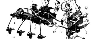
84 Sensors and valves of the brake system of a Kamaz vehicle The pressure drop sensor of a Kamaz vehicle (Fig. 313) is a pneumatic switch designed to close the circuit of electric lamps and an alarm sound signal (buzzer) when the pressure drops in the receivers of the pneumatic brake drive.
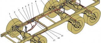
Sensors with external threads on the housing are screwed into the receivers of all brake drive circuits, as well as into the drive circuit fittings of the parking and spare brake systems, and when they are turned on, the red indicator light on the instrument panel and the brake signal lamps light up. The sensor contains positively closed central contacts, which open when the pressure rises above 441.3.., 539.4 kPa (4.5.., 5.5 kgf/cm2). Drawing. 314. Kamaz vehicle brake signal connection sensor: 1 - base; 2-membrane; 3 - movable contact; 4 - spring; 5 - fixed contact output; 6 — fixed contact; 7 - cover When the specified pressure is reached in the actuator, membrane 2 bends under the influence of compressed air and, through pusher 4, affects the movable contact 5. The latter, overcoming the tension of the spring 6, breaks away from the fixed contact 3 and breaks the electrical circuit of the sensor. The contact closes, and therefore the warning lights and buzzer turn on, when the pressure drops below the prescribed degree. The Kamaz vehicle brake signal connection sensor (Fig. 314) is a pneumatic switch designed to close the circuit of electric warning lamps during braking. The sensor contains positively open contacts that close at a pressure of 78.5..., 49 kpa (0.8..., 0.5 kgf/cm2) and open when the pressure decreases below 49... 78.5 kpa (0.5... , 0.8 kgf/cm2). The sensors are located in the lines supplying compressed air to the actuators of the brake systems. When compressed air is supplied under the membrane, the latter bends, and dynamic contact 3 connects contacts 6 of the sensor’s electrical circuit. The trailer brake control valve with a two-wire drive (Fig. 315) is designed to activate the brake drive of the trailer (semi-trailer) when each of the separate drive circuits of the tractor's service brake system is turned on, as well as when the spring energy accumulators of the drive of the spare and parking brake systems of the tractor are turned on. The valve is attached to the tractor frame with two bolts. Between the lower 14 and middle 18 housings there is a membrane 1 clamped, which is secured between two washers 17 on the lower piston 13 with a nut 16 sealed with a rubber ring. An outlet window 15 with a valve is attached to the lower body with two screws, protecting the device from the penetration of dust and dirt. When one of the screws is loosened, the outlet window 15 can be scrolled and access to the adjusting screw 8 can be opened through the hole of valve 4 and piston 13. Figure. 315. Trailer brake control valve with two-wire drive: 1 - membrane; 2 - spring; 3 — unloading valve; 4 — supply valve; 5 — upper base; 6 — impressive upper piston; 7 — spring plate; 8 — adjusting screw; 9 - spring; 10 — small upper piston; 11 - spring; 12 — middle piston; 13 — lower piston; 14 — lower base; 15 — outlet window; 16 - nut; 17 — membrane washer; 18 — middle base; I - output to part of the brake valve; Ii — output to the parking brake system control valve; III - output to part of the brake valve; Iv - output to the trailer brake line; V - output to the receiver; Vi - atmospheric output
The trailer brake control valve with a two-wire drive produces a control command for the air distributor of the trailer (semi-trailer) brake system from three independent commands, operating both simultaneously and separately. In this case, a direct manipulation command (to increase pressure) is sent to pins I and Iii, and a reverse manipulation command (to drop pressure) is sent to pin Ii. The valve leads are connected as follows: I - to the lower section of the brake valve; Ii - with reverse manipulation tap with manual administration; Iii - with the upper section of the brake valve; Iv - with the trailer brake control line; V - with car receiver; Vi - with atmosphere. In the inhibited state, compressed air always flows to terminals Ii and V, which, acting from above on the membrane 1 and from below on the middle piston 12, fixes the piston 13 in the lower position. In this case, terminal Iv connects the trailer brake control line with the atmospheric terminal Vi through the central hole of valve 4 and lower piston 13. When compressed air is supplied to terminal Iii, the upper pistons 10 and 6 simultaneously move down. Piston 10 first sits with its seat on valve 4, blocking the atmospheric outlet in the lower piston 13, and then lifts valve 4 from the seat of the middle piston 12. Compressed air from terminal V, connected to the receiver, is supplied to terminal Iv and then into the brake control line trailer The supply of compressed air to terminal Iv continues until its effect from below on the upper pistons 10 and 6 is balanced by the pressure of compressed air supplied to terminal Iii on these pistons from above. After this, valve 4, under the influence of spring 2, blocks the access of compressed air from terminal V to terminal Iv. This is how the tracking action is applied. When the compressed air pressure decreases at port Iii from the brake valve, i.e. when braking, the upper piston 6, under the influence of the spring 11 and the compressed air pressure from below (in terminal Iv), moves upward simultaneously with piston 10. The piston seat 10 comes off from valve 4 and communicates terminal Iv with atmospheric terminal Vi through the holes of valve 4 and piston 13. When compressed air is supplied to terminal I, it is supplied under the membrane 1 and moves the lower piston 13 simultaneously with the middle piston 12 and valve 4 upward. Valve 4 reaches the seat in the small upper piston 10, closes the atmospheric outlet, and with further movement of the middle piston 12 breaks away from its supply seat. Air is supplied from terminal V, connected to the receiver, to terminal Iv and further into the trailer brake control line until its effect on the middle piston 12 from above is equalized by the pressure on membrane 1 from below. After this, valve 4 blocks the access of compressed air from terminal V to terminal Iv. Thus, a tracking action is applied with this choice of device operation. When the compressed air pressure drops at outlet I and under the membrane, the lower piston 13 moves down simultaneously with the middle piston 12. Valve 4 comes off the seat in the upper small piston 10 and communicates terminal Iv with atmospheric terminal Vi through the holes in valve 4 and piston 13. With the simultaneous supply of compressed air to terminals I and Iii, the large and small upper pistons 10 and 6 simultaneously move downwards, and the lower piston 13 with the middle piston 12 - upward. Filling the trailer brake control line through terminal Iv and releasing compressed air from it occurs in the same way as described above.
When compressed air is released from port Ii (when braking with the spare or parking brake system of the tractor), the pressure above the membrane drops. Under the influence of compressed air from below, the middle piston 12 simultaneously with the lower piston 13 moves upward. Filling of the trailer brake control line through terminal Iv and braking occurs in the same way as when compressed air is supplied to terminal I. The follow-up action in this case is performed by balancing the compressed air pressure on the middle piston 12 and the sum of the pressure from above on the middle piston 12 and the membrane 1. When compressed air is supplied to terminal Iii (or when air is simultaneously supplied to terminals Iii and I), the pressure in terminal Iv connected to the trailer brake control line exaggerates the pressure supplied to terminal Iii. This guarantees the leading action of the trailer (semi-trailer) braking system. The maximum value of excess pressure at terminal Iv is 98.1 kpa (1 kgf/cm2); minimum - about 19.5 kpa (0.2 kgf/cm2), nominal - 68.8 kpa (0.6 kgf/cm2). Correction of the degree of excess pressure is applied to screws 8: when the screw is screwed in, it increases, when turned out, it decreases. The trailer brake control valve with a single-line drive (Fig. 316) is designed to activate the brake drive of the trailer (semi-trailer) when the brake systems of the tractor are operating, as well as to limit the compressed air pressure in the pneumatic drive of the trailer (semi-trailer) in order to prevent self-braking of the latter when pressure fluctuations in the pneumatic brake drive of a tractor vehicle.Figure 316. Trailer brake control valve with a single-line drive: 1 - spring plate; 2 - bottom cover; 3, 11 - thrust rings; 4 - lower piston; 5 - valve spring; 6 - exhaust valve seat; 7 - follower chamber; 5 - stepped piston; 9 - working chamber; 10, 17 - ring springs; 12 - top cover; 13 - protective cap; 14 - membrane spring; 15 - membrane spring plate; 16 - membrane; 18 - cushion; 19 - pusher; 20 - exhaust valve; 21 - supply valve; 22 - base; 23 - spring; 24 - adjusting screw; 25 - lock nut; I - output to the receiver; Ii - output to the connecting line; III - release into the atmosphere; Iv - output to the trailer brake control valve with a two-wire drive
The valve is placed on the car frame and secured with two bolts. compressed air from the receiver of the tractor-trailer is supplied to terminal I and through channel A enters the recess above the stepped piston 8. In the braked state, the spring 14, acting on the plate 15, fixes the membrane 16 simultaneously with the pusher 19 in the lower position. In this case, the outlet valve 20 is closed, and the supply valve 21 is open and compressed air flows from outlet I to outlet Ii and then into the connecting line of the trailer. When a certain pressure is reached in terminal Ii, set with the participation of the adjustment screw 24, the piston 4 overcomes the tension of the spring 23 and lowers, as a result of which the supply valve 21 sits on the seat in the piston 4. Thus, in the braked positioning, a certain pressure is automatically determined in the trailer line, less pressure in the pneumatic drive of the tractor. When the tractor is braked, compressed air flows to terminal Iv and fills the sub-diaphragm recess B. Overcoming the tension of the spring 14, the membrane 16 rises upward simultaneously with the pusher 19. In this case, the supply valve 21 is first closed, and then the exhaust valve 20 is unlocked, and the air from the connecting line of the trailer through terminal Ii, sunken pusher 19 and terminal Iii in cover 12 it escapes into the atmosphere. Air leaves port Ii until the pressure in cavity B under the membrane 16 and in the cavity under the stepped piston 8 is balanced by the pressure in the cavity above the stepped piston. With a further decrease in pressure at port Ii, the piston lowers and moves the pusher down, which closes the exhaust valve, as a result of which the release of air from port Ii stops. In this way, a tracking action is applied, and the braking of the trailer (semi-trailer) occurs with an efficiency proportional to the value of the compressed air pressure supplied to terminal Iv. A further increase in pressure at port Iv leads to the complete release of compressed air from port Ii and thus to the most effective braking of the trailer. When the tractor is braked, that is, when the pressure drops at terminal Iv and in cavity B under the membrane 16, the latter, under the influence of the spring 14, returns to its original lower location. Simultaneously with the membrane, the pusher lowers. At the same time, the exhaust valve closes and the supply valve 21 is unlocked. Compressed air from outlet 7 is supplied to outlet Ii and then into the connecting line of the trailer (semi-trailer), as a result of which the trailer (semi-trailer) is released. The Kamaz vehicle disconnect valve (Fig. 317) is designed to shut off, if necessary, the pneumatic line connecting the tractor vehicle with the trailer (semi-trailer). On Kamaz truck tractors there are three disconnect valves: on side tractors - on the rear cross member of the frame in front of the connecting heads, on truck tractors - behind the cab on the right side on a special bracket in front of the connecting flexible pipelines. Any faucet is attached with two bolts. The trailer brake control line is connected to terminal Ii; compressed air enters it through terminal I. If handle 9 is installed parallel to the axis of the valve, pusher 8 and rod 6 are simultaneously in the lower position and valve 4 is open. Compressed air from outlet I through the open valve and outlet Ii is supplied from the towing vehicle to the trailer (semi-trailer). When the handle 9 is turned 90°, the rod 6 simultaneously with the membrane, under the influence of the spring 5 and air pressure, rises upward. Valve 4 sits on the seat in housing 2, separating terminals I and Ii. The stroke of the rod 6, determined by the screw profile of the cap 7, is greater than the stroke of the valve 4. The rod 6 departs from the valve, compressed air from the connecting line through port Ii, the axial and radial holes in the rod 6 exits to the atmosphere through port Iii in the cap 7. After This allows the connection heads to be released. Connecting heads of the “palm” type (Fig. 318) are predetermined for fastening the lines of a two-wire pneumatic brake drive of a trailer (semi-trailer) and a tractor. On Kamaz onboard tractors, one connecting head, of the “palm” type for the supply line, painted red (or with a red cover), is located on the rear cross member of the frame on the right side (along the direction). Another palm-type connection head for the control line, painted blue (or with a yellow cover), is located there on the left side. Both heads are placed in such a way that the connecting holes in them are aimed to the right. On Kamaz truck tractors, the connecting heads are placed on flexible hoses and, after being disconnected from the semi-trailer, they are attached behind the cab on special brackets. The color of the heads is the same as on flatbed tractors. Drawing. 317. Disconnect valve of a Kamaz vehicle: a - the valve is open; b - valve closed; 1 - plug; 2 - base; 3 — valve spring; 4 - valve; 5 — rod spring; 6 — rod with membrane; 7 - cover; 8 — pusher; 9 — handle; I - to the connecting head; Ii - from the receiver; III - into the atmosphere When fastening palm-type heads, you need to move the protective covers 4 of both heads to the side. The heads are joined by seals 3 and scrolled until the protrusion of the head fits into the proper recess of the other, that is, until the insert 2 is connected to the lock 5.
This prevents spontaneous division of the connection heads. Sealing of the junction of the two heads is guaranteed by compression of the seals 3. When separating the tractor and trailer, the connecting heads are rotated in the opposite direction until insert 2 comes out of the groove of the clamp 5. After separation, the connecting heads must be closed with covers 4. The connecting head type A (Fig. 319) is predetermined for installation on tractor vehicles and serves to fasten the single-line pneumatic brake drive of trailers and semi-trailers, as well as to automatically close Figure. 318. Connecting head of the “palm” type for the Kamaz vehicle: 1 - base; 2 - insert; 3 - seal; 4 - cover; 5 - stopper; I—connecting head; Ii - connection of tractor and trailer heads Figure. 319. Connecting head type A for Kamaz vehicle: 1 - base; 2 — valve spring; 3 - check valve; 4 - seal; 5 - cover; 6 — ring nut; 7 — rod; I - connecting head: Ii - connection of heads type A and B
On Kamaz onboard tractors, the connecting head type A, painted black, is located on the rear cross member of the frame on the left side (along the way) so that the connecting hole in it is directed to the right. On Kamaz truck tractors, the type A connecting head is also painted black and is located on a flexible hose. After detaching from the semi-trailer, the head is attached behind the cab on a special bracket. When coupling a tractor-trailer with a trailer, the protective cover 5 is moved to the side at the connecting head. The head of type A of the tractor is joined to the head of type B of the trailer with seals 4. In this case, the rod 7 of the head of type B enters the spherical recess of the valve 3 of the head of type A and tears the valve away from seal 4. After this, the heads are rotated until the protrusion of the single head fits into the proper recess of the other head. The head stopper type B fits into the recess of the guide head type A, preventing spontaneous division of the heads. The joint of the heads is sealed by compressing the seals 4. When the tractor and trailer are separated, the connecting heads are rotated in the opposite direction until the protrusion of the single head comes out of the groove of the other, after which the heads are separated. In this case, the valve, under the influence of the spring, is pressed against the seal 4 and automatically closes the connecting line, preventing the release of compressed air from the pneumatic brake drive of the tractor. After disconnecting, close the head with lid 5. Next page»»»»»»
- 10. 11. 12. 13. 14. 15. 16. 17. 18. 19. 20. 21. 22. 23. 24. 25. 26. 27. 28. 29. 30. 31. 32. 33. 34. 35. 36. 37. 38. 39. 40. 41. 42. 43. 44. 45. 46. 47. 48. 49. 50. 51. 52. 53. 54. 55. 56. 57. 58. 59.60. 61. 62. 63. 64. 65. 66. 67. 68. 69. 70. 71. 72. 73. 74. 75. 76. 77. 78. 79. 80. 81. 82. 83. 84. 85. 86. 87. 88. 89. 90. 91. 92. 93.
coming
Do-it-yourself rewinding of the KamAZ electronic speedometer
The need to rewind the speedometer arises when you need to change the dashboard or engine. Winding should be done on all parts of the speedometer at once: the odometer measures mileage, the tachometer shows speed. You can only rewind the speedometer readings using a special device that will help you fine-tune all the indicators.
Different types of speedometers work in conjunction with certain sensors, for example, PPS 87.3802 is designed to work with speed sensors 4202.3843, and is suitable for the following KamAZ models: 4310, 5510, 55102, 53212, 43118, 5350 and others.
Electronic speedometers operate thanks to a three-phase signal coming from the generator. A special device - “winder”, “twist” - automatically winds the speedometer and odometer.
To adjust the speedometer, do you turn to specialists or do it yourself?
Tell me how to check the electronic speedometer?
In order to check the electronic speedometer, you first need to understand a little about how the electronic speedometer works and how it works. And it consists of an inductive sensor (installed on the gearbox) and a pointer on the dashboard. Since there is no drive shaft (such as on a mechanical speedometer), the readings are transmitted in the form of frequency pulses from the sensor to the gearbox converted from the rotational speed of the secondary shaft of the box. This number of these pulses exactly corresponds to the speed of the car. And the speedometer converts pulse signals into a mechanical indication.
When the electronic speedometer does not work, to check it you will need to: First remove the speed sensor. Then turn on the ignition and apply a flat (preferably wide) screwdriver to the underside of the inductive sensor, and then quickly move it back and forth. If the speed sensor is working properly, a pulse signal is generated and this should cause your speedometer needle to deflect. If the arrow does not move, you need to remove the dashboard to get to its connection connector.
Next, connect the multimeter probes to the sockets of the speedometer connector (on some cars they are marked on the connector itself), set the tester handle to voltmeter mode with a range of 0–3V and repeat the test with a screwdriver again. Now, when you remove the screwdriver from the speed sensor, the multimeter (voltmeter) needle should deviate; if this happens, then the sensor and its wiring are working, but the electronic speedometer is faulty and it’s worth checking it. When there is no change in readings on the multimeter or the needle does not deviate, then the sensor itself is faulty or there is a problem with its wiring.
Arduino speedometer for KamAZ
Replacing the Kamaz speedometer
Launching the speedometer AP 121.3802 from a Kamaz vehicle on the table
Speedometer drive ME 307 MAZ speed sensor
How to adjust the speedometer and odometer on a Kamaz
How to check the speedometer (speed) sensor Gazelle, Volga 405 internal combustion engine
The speedometer does not work. What is the reason?
Sensor on KamAZ.avi
HOW TO CHECK THE SPEED SENSOR
speedometer failure on Kamaz
The KamAZ brake system is thought out to the smallest nuances, since the technical condition of the vehicle and the possibility of safe driving depend on it. The installed KamAZ speed sensor is an important device, as it allows you to monitor the technical performance of the vehicle.
How to check the KAMAZ speedometer | KAMAZ
Launching the speedometer AP 121.3802 from a Kamaz vehicle on the table
How to adjust the speedometer and odometer on a Kamaz
Rewind 3 x. old-style Kamaz phase speedometer
Speedometer KAMAZ Euro 3
PT 8114 VZEP for KAMAZ
speedometer failure on Kamaz
How to check the speedometer (speed) sensor Gazelle, Volga 405 internal combustion engine
The speedometer does not work. What is the reason?
Winding up an electronic speedometer with your own hands
How the speedometer works
- KAMAZ technical wheels
- Ars on KAMAZ chassis
- KAMAZ 5320 arek
- Why is the Urals more passable than KAMAZ?
- KAMAZ digital pressure gauge
- Box KAMAZ 141
- Engine KAMAZ Euro 2 oil leak
- Crankshaft position sensor KAMAZ 6520
- KAMAZ shuttle broiler
- Online video of KAMAZ accident
- KAMAZ 4308 prototype
- Indicator lamps of the KAMAZ 55111 instrument panel
- Manual pre-start pump from KAMAZ
- KAMAZ different people text
- KAMAZ starter relay is on
Home » Clips » How to check the KAMAZ speedometer
Where is the speed sensor located?
In most cases, the sensors are located at the gearbox and are connected by a special drive to the speedometer, the data of which is read to determine speed and mileage.
Thus, it is advisable to find functional units taking into account the layout of a specific KamAZ model and the specifics of the technical system. The devices have different designs, since the influence of the location of the unit is noted.
Contact sensors are considered less reliable due to the interaction of spare parts and constant rotation. However, such devices are often used, as they are installed instead of a mechanical speedometer drive and allow you to modernize brake systems. Contact models are characterized by optimal reliability.
Sometimes on KamAZ, speed sensors can be installed without direct contact with the rotating shaft. To measure speed, a drive disk or rotor is often used, since this device is auxiliary. Contactless models are becoming in demand, as a result of which they are often installed on modern KamAZ models.
The KamAZ zf speed sensor is also popular, as it is created according to modern standards. The package includes a modern transfer case that increases reliability. A working unit allows you to find out the exact technical characteristics of the vehicle. Over the past few years, such devices have been successfully used on domestic vehicles, including KamAZ. Motorists remain satisfied, because with proper regular maintenance, additional benefits are noted, or rather, economical fuel consumption and a minimal amount of substances released into the air.
Fact! Any sensors work only on physical principles. Contact devices usually use the Hall effect and magnetoresistive effect (MRE), optocouplers. Non-contact sensors most often operate on the Hall effect and much less frequently on MRE.
Operating principle of the speed sensor
Most sensors operate on the Hall effect. To determine speed and mileage, frequency pulses are used, which are sent at a certain interval. Impulses arise when the wheels rotate, so the mechanics calculate the data and they are displayed on transport devices. Typically, up to 6 thousand signals are issued for every kilometer. The KamAZ Euro speed sensor is considered the most advanced, since it was created on the basis of modern standards and European experience in the automotive sector, and is distinguished by its information content and accuracy.
Contact sensors
The basis of such devices is a corresponding microcircuit with a special plate and an amplification circuit. The chip and magnet do not move. To change the magnetic field and read pulses, rings with special slots rotate. The presence of small connectors allows you to read indicators for display on devices. The old-style KamAZ 5320 speed sensor was made using this principle.
However, on domestic models, including 4308, 53504 (the name appeared on some modifications after the restyling of 44108), the technical system has been improved. You can also read about Separating the pads on a KamAZ - Correct installation of the pads.
Non-contact sensors
The device operates on the Hall effect, but the design is different. On the shaft of the unit (gearbox or axle gearbox) there is a rotor or impulse disk with areas that are magnetized. There is a gap between the Hall chip and the rotor, but pulse signals are successfully read through standard connectors. This KamAZ speed sensor circuit is considered reliable, since spare parts interact less with each other and unwanted mechanical influence is prevented.
Possible malfunctions of the speed sensor
KamAZ 55102, 65115 often have device malfunctions, because such models have been produced for a long time and there are numerous used models on the domestic market. Malfunctions are manifested by problems with idle speed (the car may stall), corrosive changes in contacts.
- lack of information about mileage and speed due to inoperative devices;
- malfunction of the engine (impaired idling speed, excessive fuel consumption, loss of power);
- serious problems with security systems.
Note! Be sure to use a sensor that was installed earlier or recommended by the car manufacturer. If the unit is incorrectly selected, it will not be possible to install it, switching between speeds will not occur correctly, or the technical data will not be read correctly.
Malfunctions and repairs
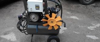
Malfunctions of the moisture separator and their causes:
- Liquid leaks from the tank, the automation is unstable. This may be due to a violation of the integrity or deformation of the body or glass due to mechanical stress.
- The switch does not work. The cause of the breakdown may be a worn-out element that is constantly exposed to steam.
- The humidity meter is displaying incorrect data. This may be due to damage to the measuring device.
- Violation of the thermal regime. Such a breakdown may be caused by malfunctions in the automation.
- The device does not cope with its functions. In this case, the cause of the breakdown is worn out filter elements.
Procedure for carrying out repair work:
- Remove the back and front panels of the entire mechanism.
- Remove the top cover.
- Disassemble the back panel.
- Unscrew the fixing bolts from the frame.
- Remove the 4 screws from the panel.
- Inspect the compressor and control unit for damage and defects.
- Replace worn and damaged parts with new ones. Replace filter blades.
- Check the water level sensor and pressure indicator.
Important Features of operation and repair of autonomy on KamAZ trucks
Speedometer functions
The sensor is primarily connected to the speedometer. For this reason, you need not only to know where the KamAZ speed sensor is located, to carefully monitor its serviceability, but also to take into account the functionality:
- speed measurement and display;
- displaying information about the distance traveled;
- informing about the current time;
- alarm about exceeding the permissible speed;
- measurement of the number of pulses for correct reading of characteristics.
Speed sensors on KamAZ 43118 vehicles and other models must be operational for safe driving, both in the city and on the highways.
Air suspension of KamAZ cab
Air suspension is one of the best suspension options as it combines shock-absorbing and damping effects.
Cab air suspension is necessary to reduce the negative impact of vibrations both on various mechanisms and on the driver. It also increases comfort when traveling off-road.
Air springs filled with air or nitrogen allow you to adjust the ground clearance (if installed on the front or rear axle), for example, at high speeds on the highway, the ground clearance is reduced, shifting the center of gravity, which adds inertia. When driving on dirt roads, high ground clearance is required, which is also provided by independent air suspension, such as the KamAZ 43118.
The air suspension of the cabin dampens various vibrations that arise from driving on bumpy roads, which keeps some parts and components in good condition longer. The cabin can also be raised and lowered depending on the driver's needs.
It is easy to find videos on the Internet showing in detail the principle of operation of such a suspension. In general terms, the air pressure in the cushion is regulated, allowing the cabin to be raised or lowered.